Close
0%
0%

1Bitsy 1UP

ARM Cortex-M4F based retro inspired handheld game console.

Similar projects worth following
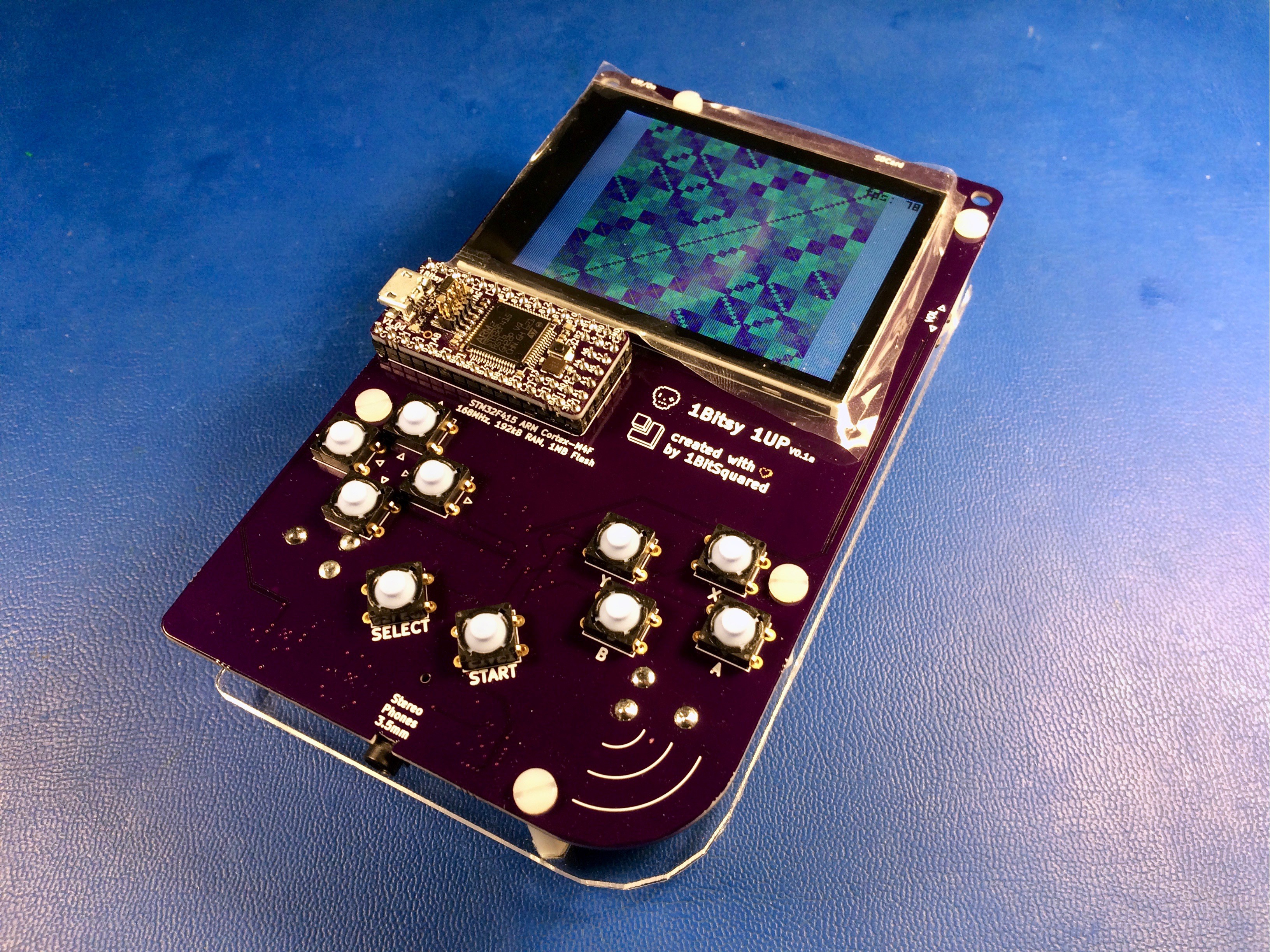
1Bitsy 1UP is a retro inspired handheld game console, the design is based on the 1Bitsy STM32F415RGT6 ARM Cortex-M4F 168MHz 192kb RAM and 1MB Flash micro controller. 2.8" TFT with capacitive touch, SDCard Reader and a few other components. In retro spirit the platform has a few semi arbitrary constraints. Lack of enough memory for a frame buffer graphics and lack of graphics acceleration hardware, gamepad connected over shift registers, using a built in 12Bit DAC for audio instead of a dedicated I2S device. But it is meant to be extended in future hardware revisions, all new added future features add interesting hacking capabilities while remaining transparent to software written for older devices. This combination of design decisions makes the platform an interesting puzzle and challenge while using modern but affordable off the shelf components.

The project is based on the 1Bitsy STM32F415 embedded development platform. We also use the Black Magic Probe JTAG/SWD programmer and debugger heavily for software development.

Here is a list of the current design decisions, constraints and ideas:

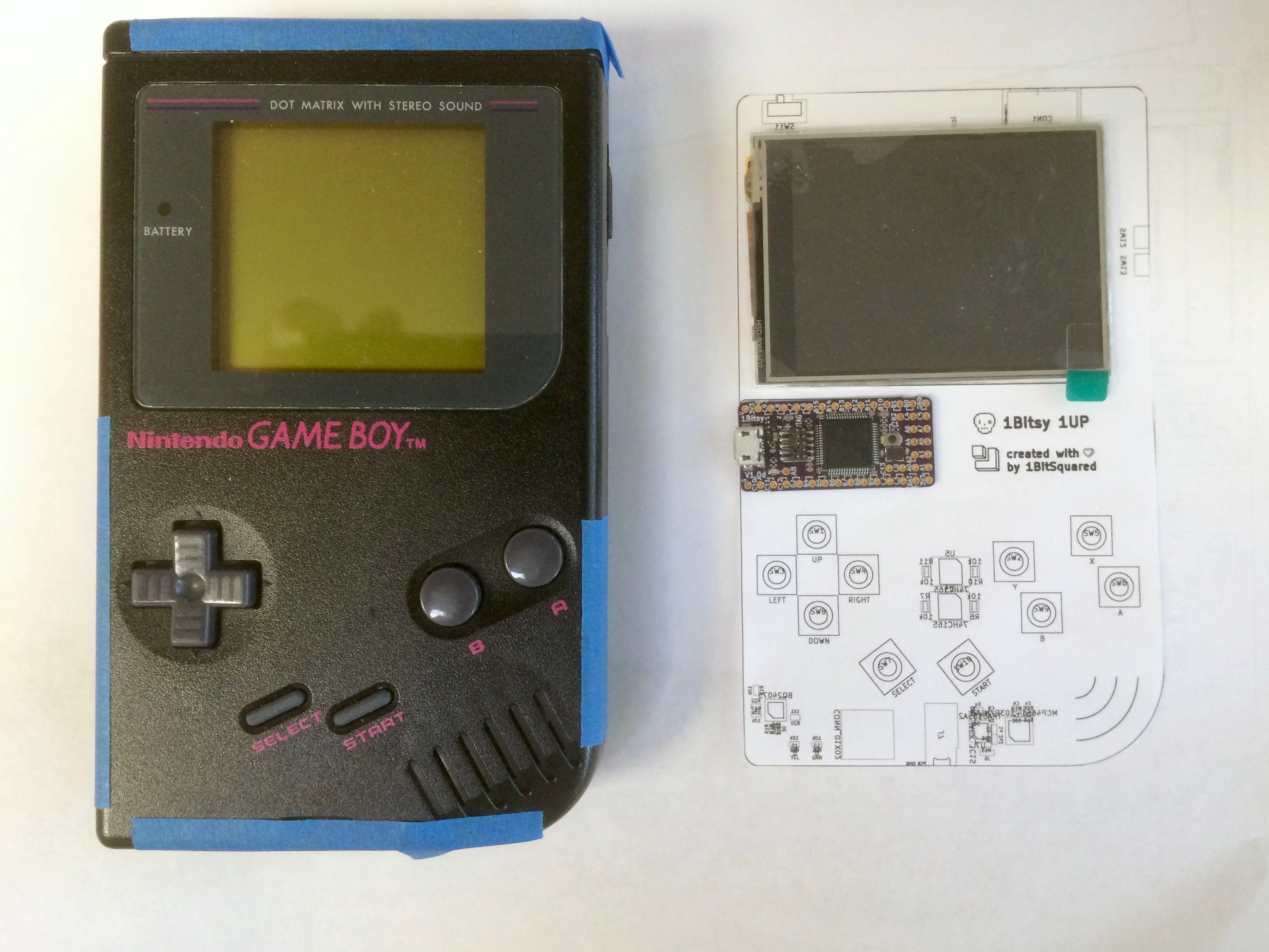
  • Formfactor: PCB the size of the inside of a GB DMG (the gray one) This will hopefully eventually allow us to put the 1UP pcb inside a modified GB DMG case, either original or new molds sold by several online stores.
  • Main CPU: All code should be able to execute on a 1Bitsy that is fitted with an STM32F415RGT6. That particular chip (due to the package size) does not contain external ram support or LCD display engine. Making LCD drive little bit more tricky. It is a nice constraint that makes coding for the platform bit more of a challenge in the style of classic conloles and 8bit computers because it does not have enough memory for a full framebuffer. ("racing the beam" FTW)
  • LCD: The LCD is a 240x320 TFT display with capacitive touch, connected through the 8bit parallel interface to the 1Bitsy. This allows us to push the data speed to the display quite high and reach good framerates that would not be possible through the SPI interface. (Early tests are able to push 120MBit of data over the parallel interface to the TFT display, as opposed to 48MBit theoretical maximum of the SPI interface) The capacitive touch screen adds an interesting aspect of control that was not available on classic consoles prior to DS. (That was also resistive not capacitive)
  • Audio: We are connecting the STM32F4 built in DAC lines for audio generation. This is not as high quality as an i2s part but will likely make things "interesting". We do have a headphone amplifier (optionally speaker amplifier) connected to the DAC output as well as an i2c controlled dual digital potentiometer, to adjust volume.
  • Controls: The gamepad consists of the classic D-Pad, ABXY, Select, Start set of buttons. Because we have the capacitive touch no other analog controls are considered necessary. The buttons are connected through two 8bit parallel to serial shift registers. (the volume up down buttons are also connected to the shift register lines)
  • Storage: To simplify storing games and data in large quantities we have connected a microSD card over the SDIO interface to the STM32, allowing for reasonabely fast load and save times and maybe even some other interesting hacks?
  • Expansion: The platform will receive future expansions and improvements that will strive to remain transparent. Meaning all code written for the first version of the platform should work either out of the box or only with very minor modifications.

The display used is a TFT LCD with I2C CapTouch and ILI9341 driver. (should be compatible with the display sold by Adafruit on their breakouts as well as the buydisplay.com 2.8" tft with CapTouch sensor)

The most basic design consists of:

  • 1Bitsy STM32F415RGT6 (168MHz, 192kb RAM, 1MB Flash)
  • 240x320 2.8" TFT with capacitive touch and PWM backlight control
  • D-Pad, ABXY, Start, Select buttons (SNES circuit)
  • DAC audio out to headphones. (speakers optional)
  • SDCard connected over SDIO interface

Second tier addons for quality of life:

  • Lipo battery and charger built in
  • Speaker audio

Future "transparent" expansions: These expansions will contribute to new and interesting hacks possible on the platform, they are not considered forward compatible but backward compatible. This means that we do not anticipate the expansions to exist from the beginning of the platform life and the software written at that time will not support the future expansions, but the old software has to function as is or only with very minor changes on the new device that contains the new expansions.

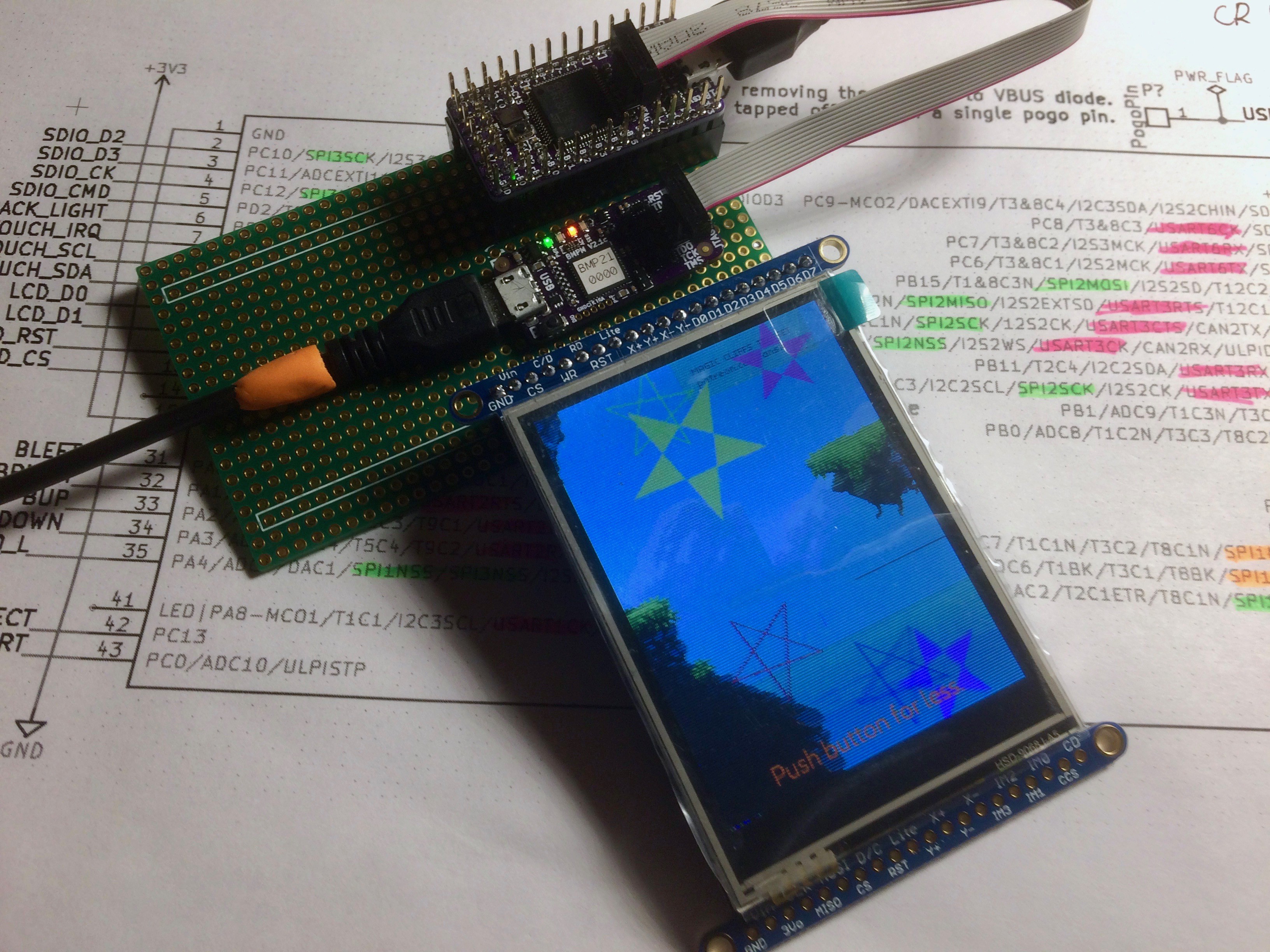
Early video test using an Adafruit 2.8" TFT and 1Bitsy. The demo shows anti aliasing, and multi layer object overlay with alpha channel and moving background bitmaps. The demo does not use a framebuffer but rather a racing the beam inspired DMA...

Read more »

1bitsy-1up.pdf

1bitsy 1UP V0.1 schematic.

Adobe Portable Document Format - 199.07 kB - 06/30/2017 at 09:57

Preview

  • DefCon25 Post Mortem

    Piotr Esden-Tempski08/04/2017 at 20:43 2 comments

    DefCon 25 came and went. It was a great event, despite being in Las Vegas, that is not meant for human life. But as always I met a bunch of new and old friends, making it all worth while. :)

    First good news is that I was able to assemble all 3 prototypes of the 1Bitsy 1UP V0.1 before leaving for DefCon. This is not even remotely as many as some of the other members of the #badgelife community. Other badge projects were assembling between a few dozen up to 1k+. But considering the complexity and the fact that this is just the first prototype I am still reasonably proud of myself. :P

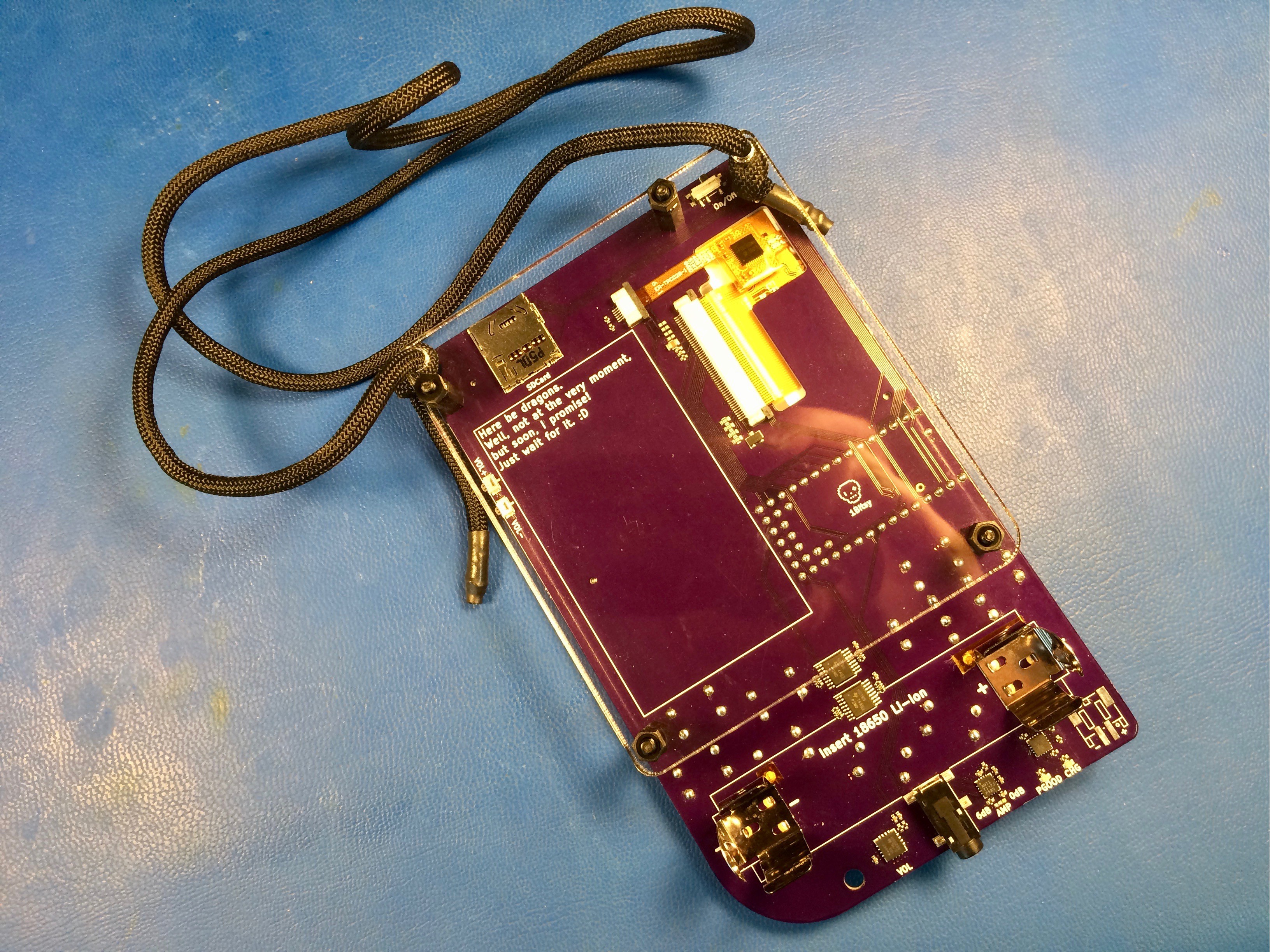
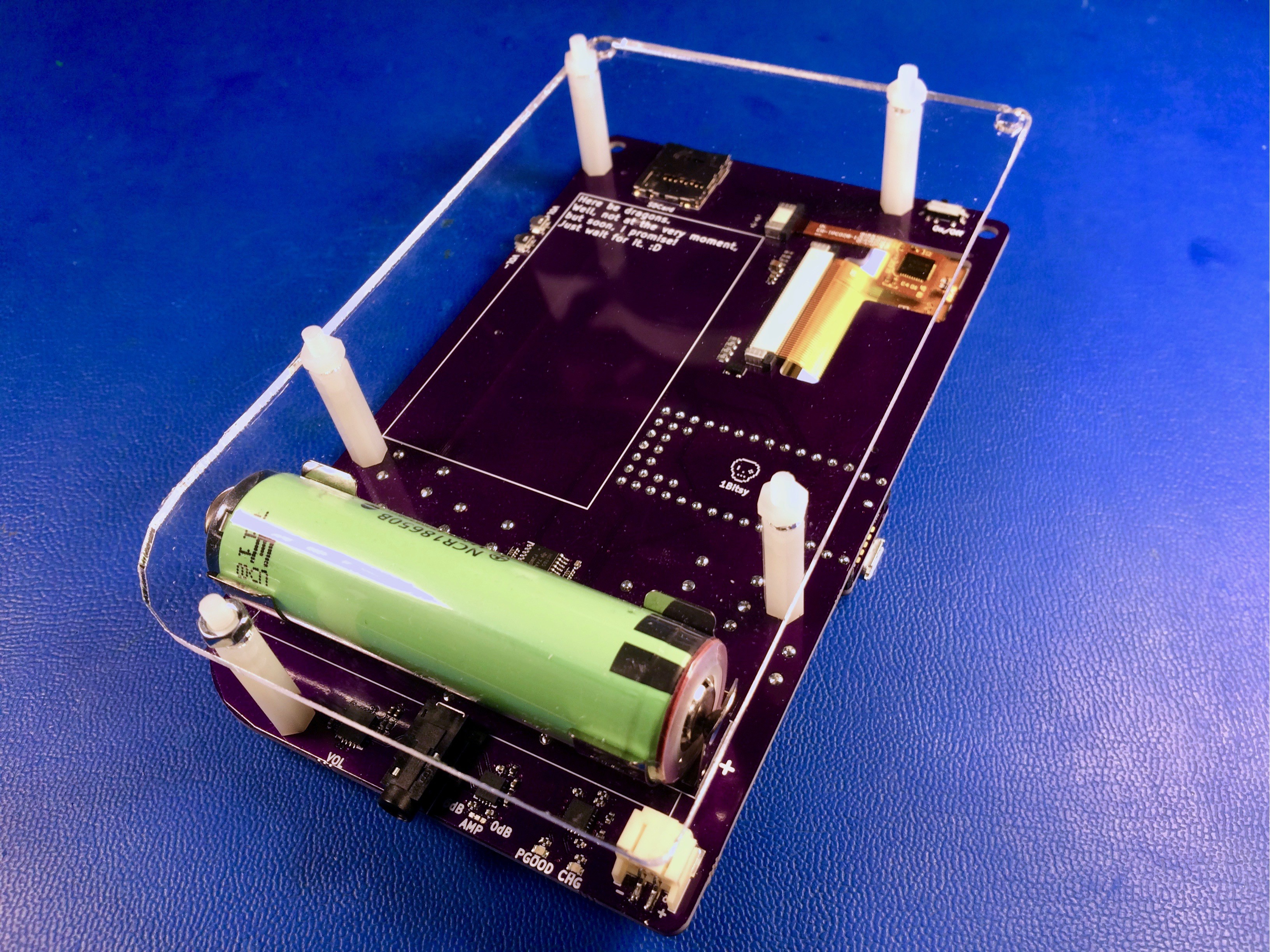
    The 1Bitsy 1UP also got updated laser cut acrylic backing plate that does not cover the whole back of the device. The reason behind it is, that the previous plate prevented me from swapping the 18650 batteries out in case I needed to, but more importantly it was making the device a bit too bulky for my taste. It has to feel good in the hand when you hold it after all. The backing plate provided a good mounting place for the paracord lanyard to be attached. Feeding the paracord through the M3 holes turned out to be quite a challenge but it worked out. NOTE TO SELF: make the lanyard holes larger in the next hardware revision! :D

    In the last week before the con, I did not spend any time on the software. The one thing that I was really missing on the software side, when leaving for the event, was sprite rendering. I already had a minimal sprite sheet loaded into the assets of the 1UP but it required some sprite rendering code. On the airplane I implemented a renderer capable of drawing sprites with one tile, two tiles and four tiles, resulting in 8x8, 8x16, 16x8 and 16x16 pixel sprites. The animation/game code has to reassign the tile id on each step to create animations the same way it is done on the old 8bit consoles. This api is actually a lot of fun to use and pretty easy to implement. While I was already at it I thought I would also add control of the LCD backlight to decrease the chance of blinding people.

    I did not want to stress other passengers out so I did not pull out the 1UP to test my code, obviously I made a few mistakes while writing the code blindly, so as I had the first chance to test the new code everything was black, I decided to disable the backlight code for the duration of the con. The sprite code only needed a few minor tweaks to get working. Now you can control the background with the D-Pad and the sprite with the ABXY buttons.

    Just after my arrival on Thursday I rushed to catch the very end of the #badgelife meetup. It was amazing, so many creative people making awesome electronics. I hope this event will gain more official status in future and the community will continue growing.

    One very good request I got early on was from Jared Boone aka. Sharebrained. He suggested that the game screen should have a timeout that makes the screen auto animate after not detecting any gamepad activity for a while. I quickly followed his advise and added the feature.

    Walking around with the 1Bitsy 1UP around my neck through DefCon, I was frequently asked where and how one can get their hands on the device. Some people thought it was a real gameboy, or gameboy advance, around my neck. :D I'm glad to hear that I'm not alone in the nostalgia for the old 8bit handheld platforms. This was very motivating, and am looking forward to continue work on the 1Bitsy 1UP. If everything goes well maybe we will be able to offer a future version of the hardware to a wider audience and make it into an actual #badgelife badge that people can add to their collection. Other projects like the AND!XOR, Mr Robot Badge, Queercon 14, Mr Blinky Bling, Hackerwarehouse and all the other #badgelife badges are a huge inspiration, so a big thank you to all of them! :D

    If you are interested make sure to follow the project here on hackaday.io and I will continue updating...

    Read more »

  • It is ALIVE!

    Piotr Esden-Tempski07/15/2017 at 19:26 0 comments

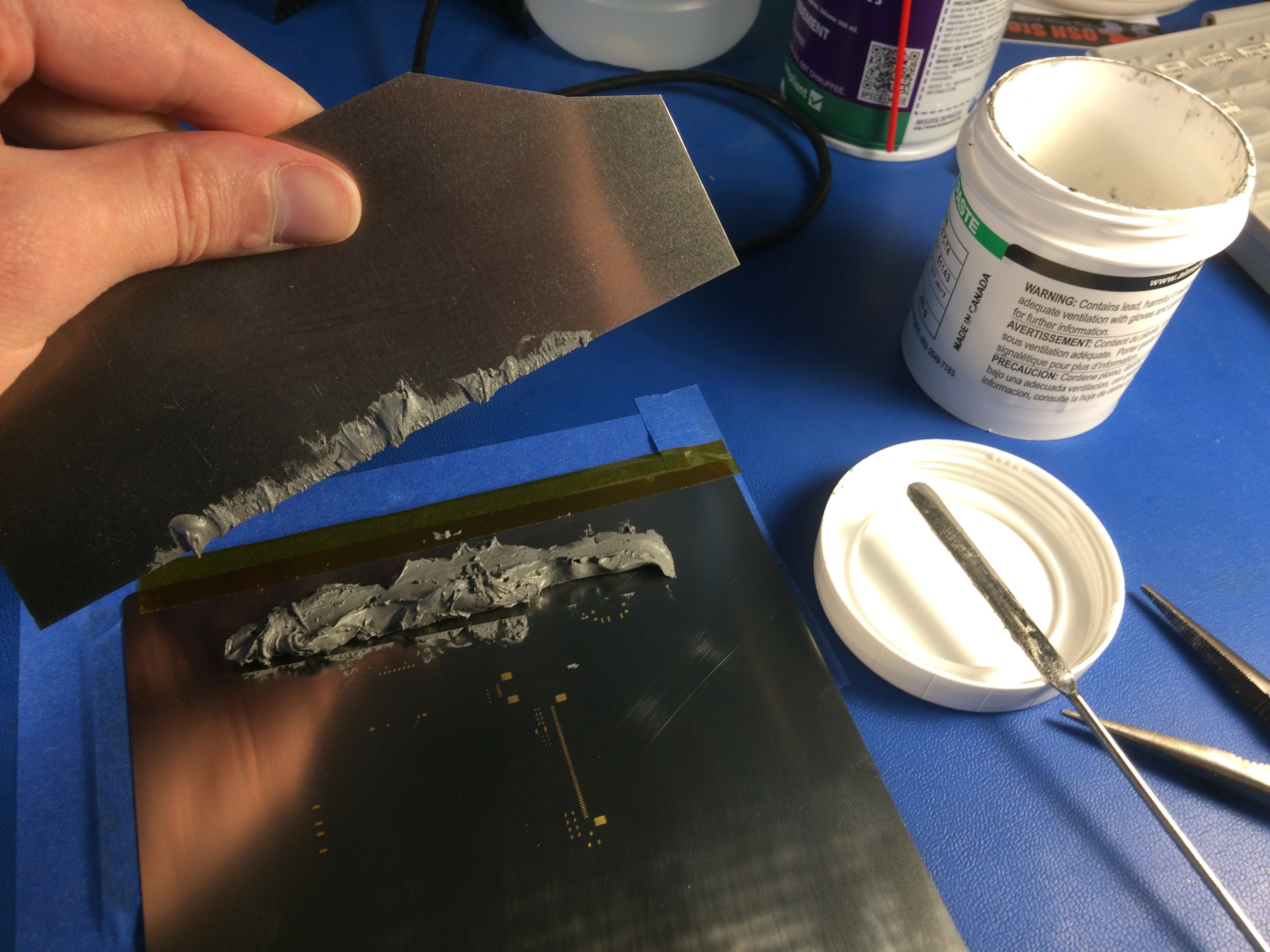
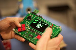
    Yesterday I have assembled the SMD parts on all three prototype 1Bitsy 1UP boards. Thanks to a stencil and reflow oven the longest part was placing the parts on the board by hand. (these are too few boards to program a pick and place for, obviously) At the end it only took two and a half hours to put it all together. The 1UP does not have that many placements, yet. :D

    Next I went to the local hackerspace to cut out some backing plates for the devices. It took me a little bit to learn how to create files from kicad that the laser software would accept. (they have an older but made by a large company laser cutter, it is mind blowing how utterly terrible the drivers for that thing are. Also QCad is a horrible software package, but it seems to be the best software to generate prints that the laser cutter will understand, it is just piles of annoying things >_< ) At the end I did end up with usable acrylic plates, unfortunately I forgot to try making cutouts for the battery. Something I have planned to decrease the thickness of the system.

    But I got some prototypes made and learned the workflow that this laser cutter accepts. YEY! :D

    Next I soldered in all the through hole parts on the boards, and started testing things one by one. I have found some solder points that were not properly reflown. (the standard flat JST connector was not properly soldered) But then things started working one after another. I had to do some minor changes to the gamepad shift register read out code. I am actually not sure why it worked with the SNES controller in the first place. :)

    But all the parts that I have code for seem to be working fine now. I have it sitting here next to me running the munching squares demo. I am really curious how long that Panasonic 3500mAh battery will last. :D ... According to math it should last a very very long time. :)

    Next goal is to finish assembling the other two systems. And maybe make another trip to the hackerspace to tinker with some other plate solutions. Otherwise I need to write lots of code and test the other subsystems. aka. SDCard reader, audio out (including digital potentiometer) and capacitive touch. I am very excited to see the hardware work! :D

  • Stencil Arrived

    Piotr Esden-Tempski07/15/2017 at 00:03 0 comments

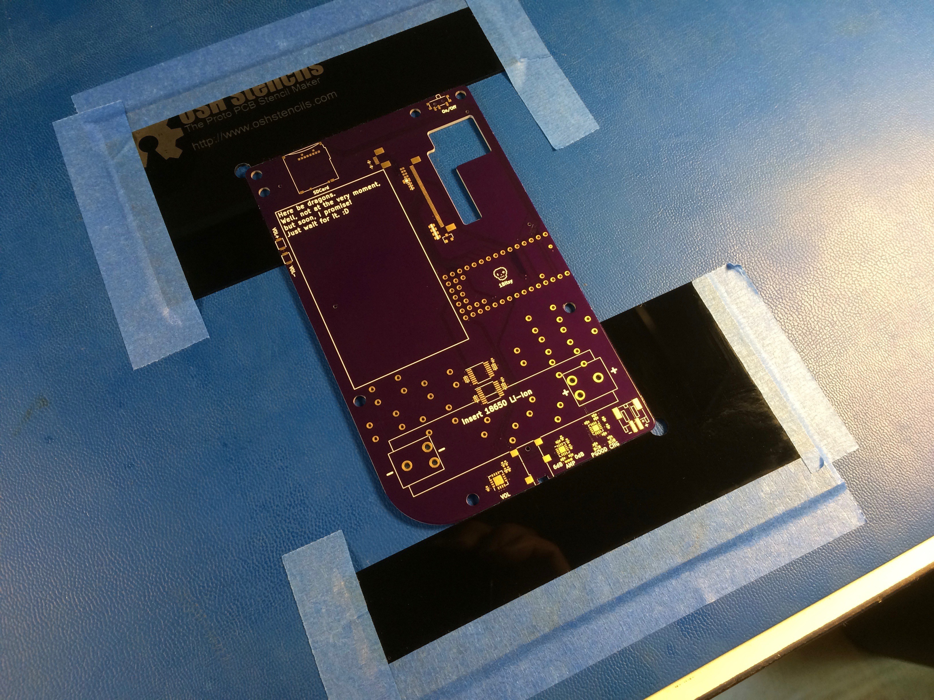
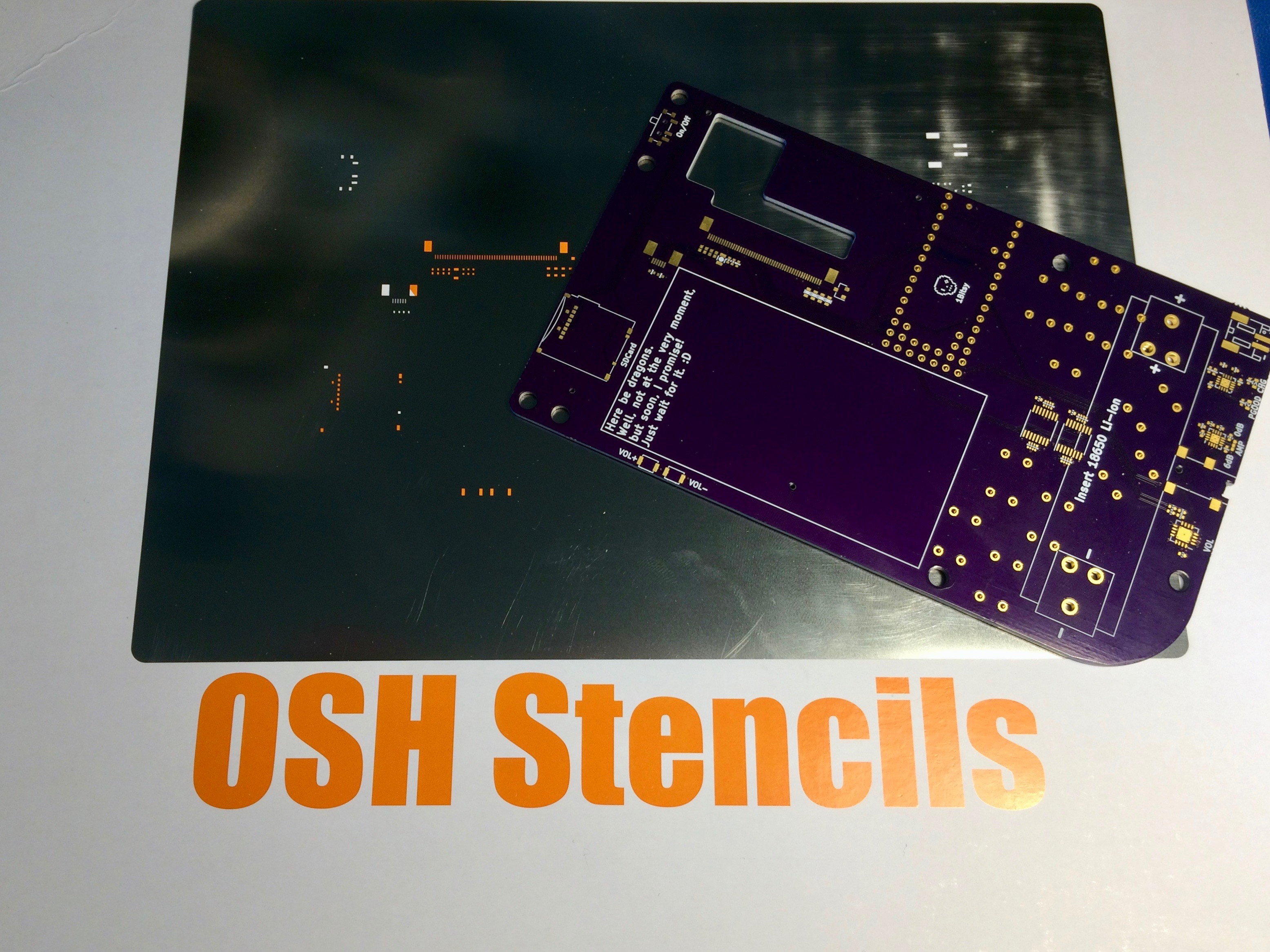
    Today I have received the solder paste stencil from OSHStencils. (It is really nice they are so fast and I was able to get it before the weekend :) )

    Now I can finally get to assembly. I know I could either do the assembly by hand or slobber some solder paste on the pad, put the parts down and then rework. But I like doing things clean and tidy and "right" :D so stop judging me!

    Now we will see how many mistakes I made in the board design. Wish me luck!

  • PCBs Arrived!

    Piotr Esden-Tempski07/13/2017 at 06:49 0 comments

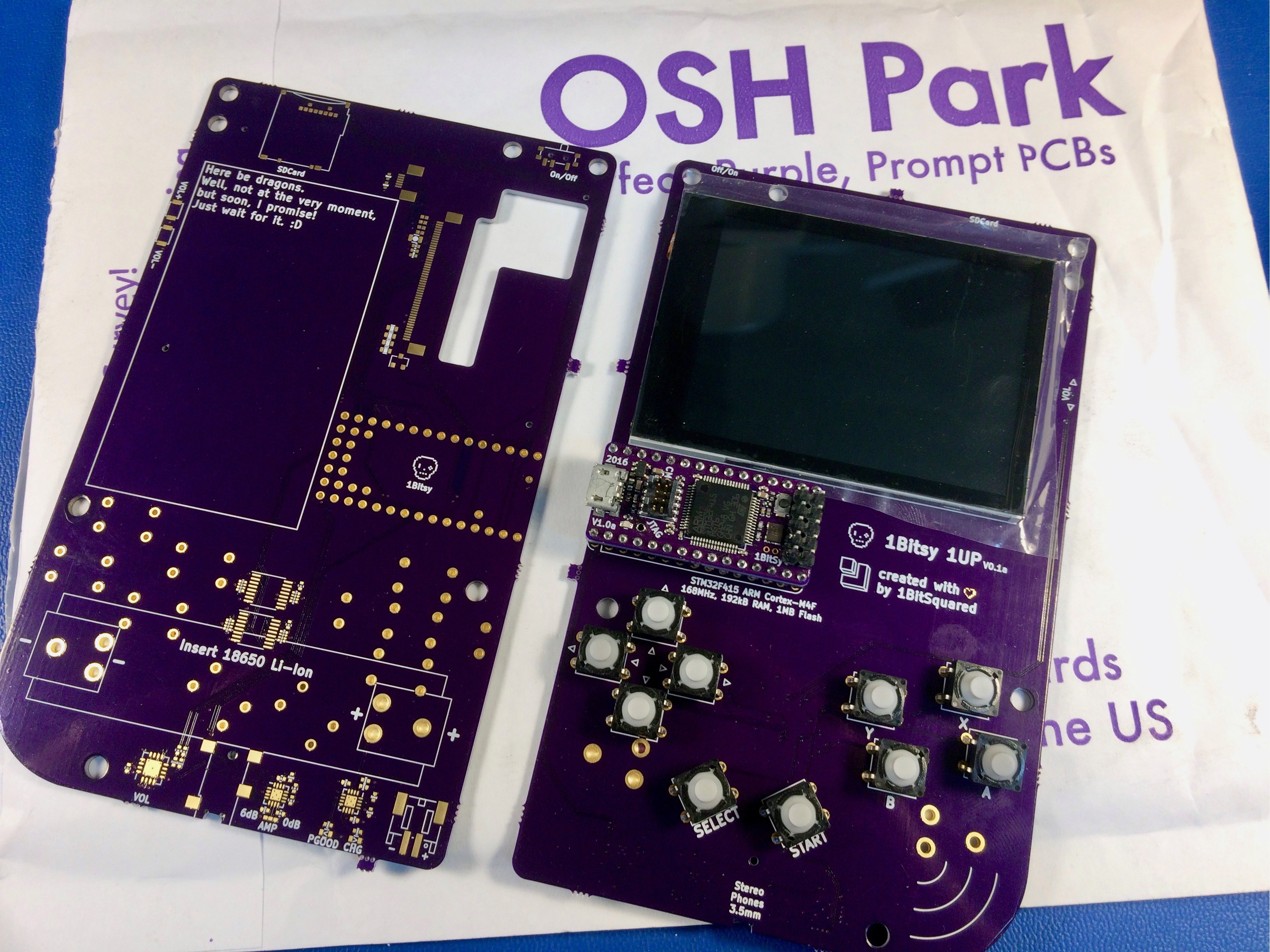
    To my huge surprise I have received the 1Bitsy 1UP boards today! OSHPark estimated that the boards will arrive at their facility on the 16th so I really was not expecting to get the boards today. This resulted in me not rushing to order the stencils, as I wanted to order them together with something else that I am working on. I went ahead and placed the order today, now I will have to wait a little bit for the stencils. Fortunately OSHStencils is very fast.

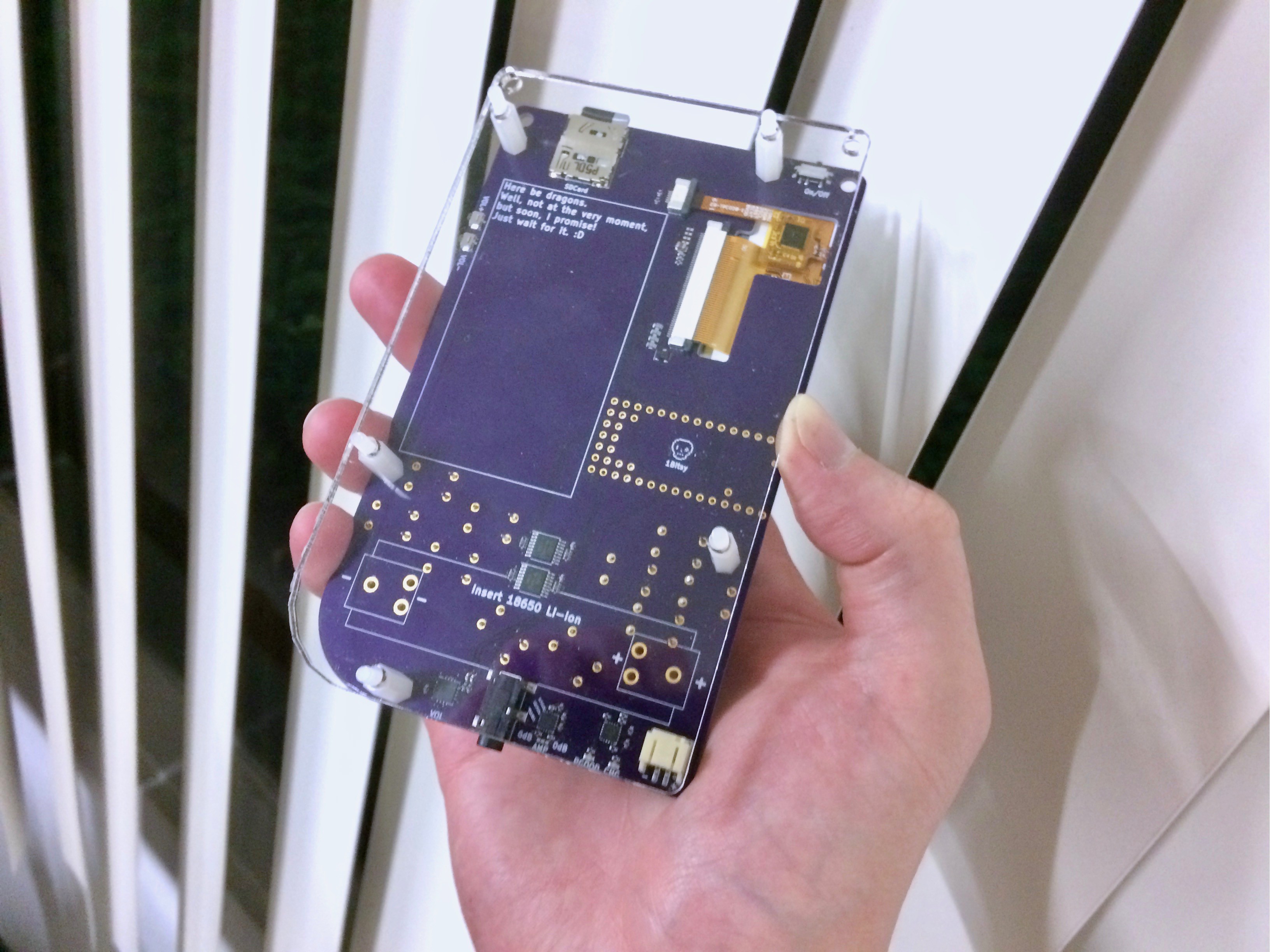
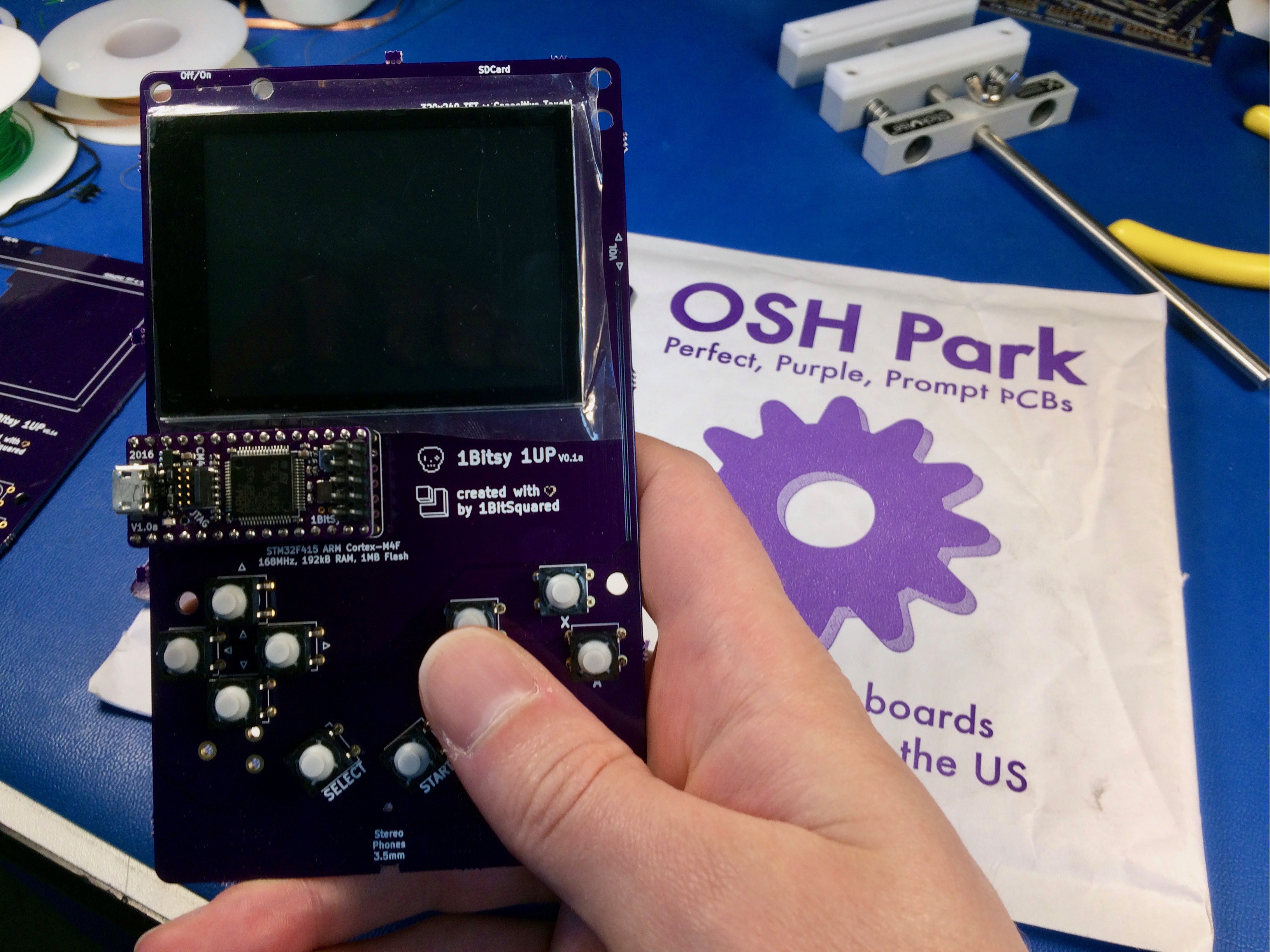
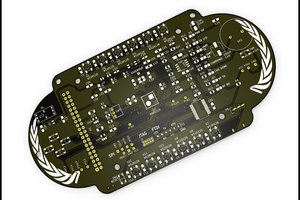
    I am very excited about the boards, they look really stunning in person. The button placements seems to be in a good spots. The whole device does feel very good to hold, very similar to the original that served as inspiration for the mechanical design. Maybe a little bit more like the pocket due to thickness, even when I mock up the backing plate.

    Can't wait to assemble and test the boards and start displaying some graphics on the display. The stencil should arrive here on Friday. So I can spend some of the remaining time writing more software. :D

  • Tile Rendering and Game Pad

    Piotr Esden-Tempski07/09/2017 at 21:47 1 comment

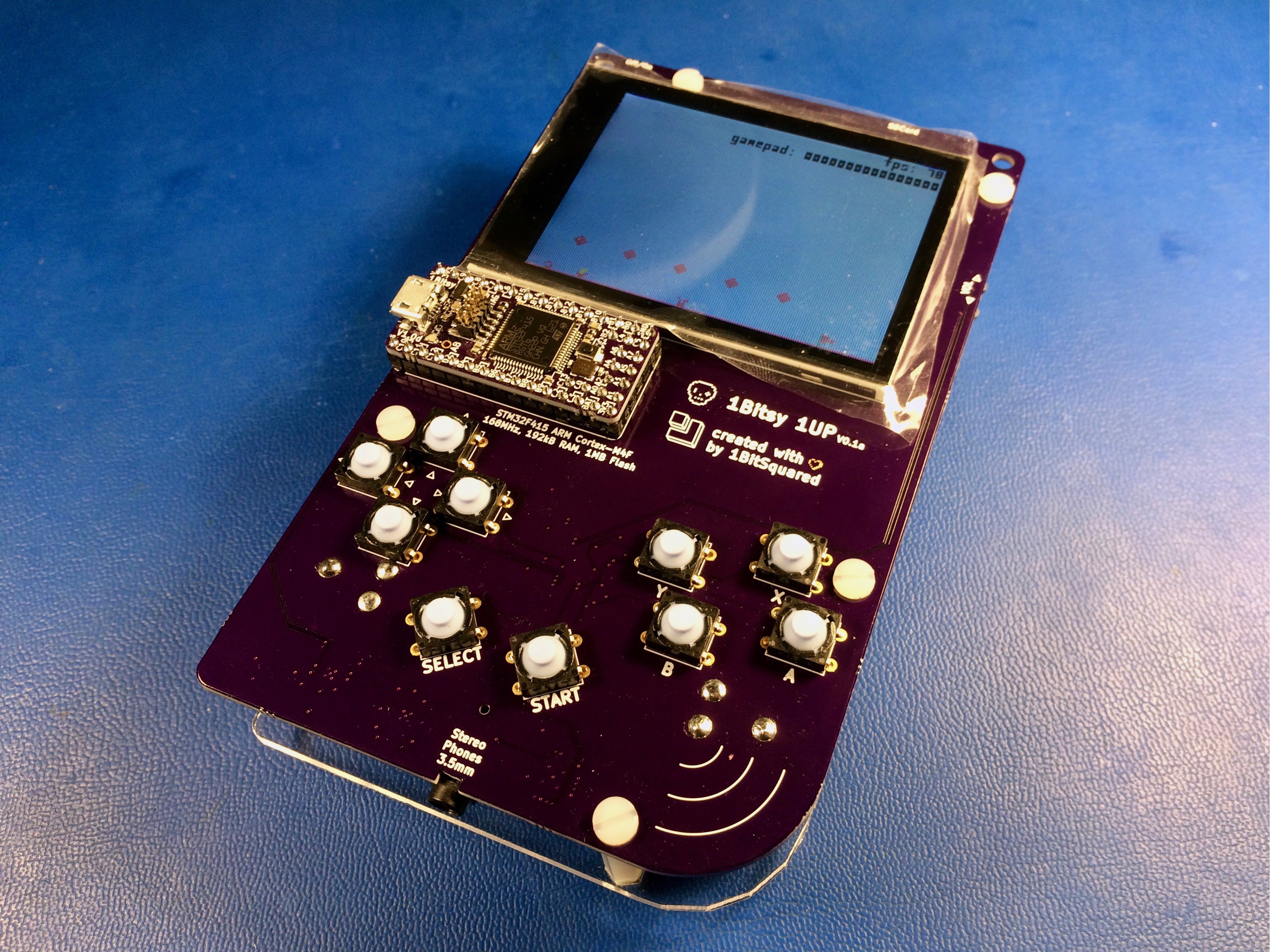
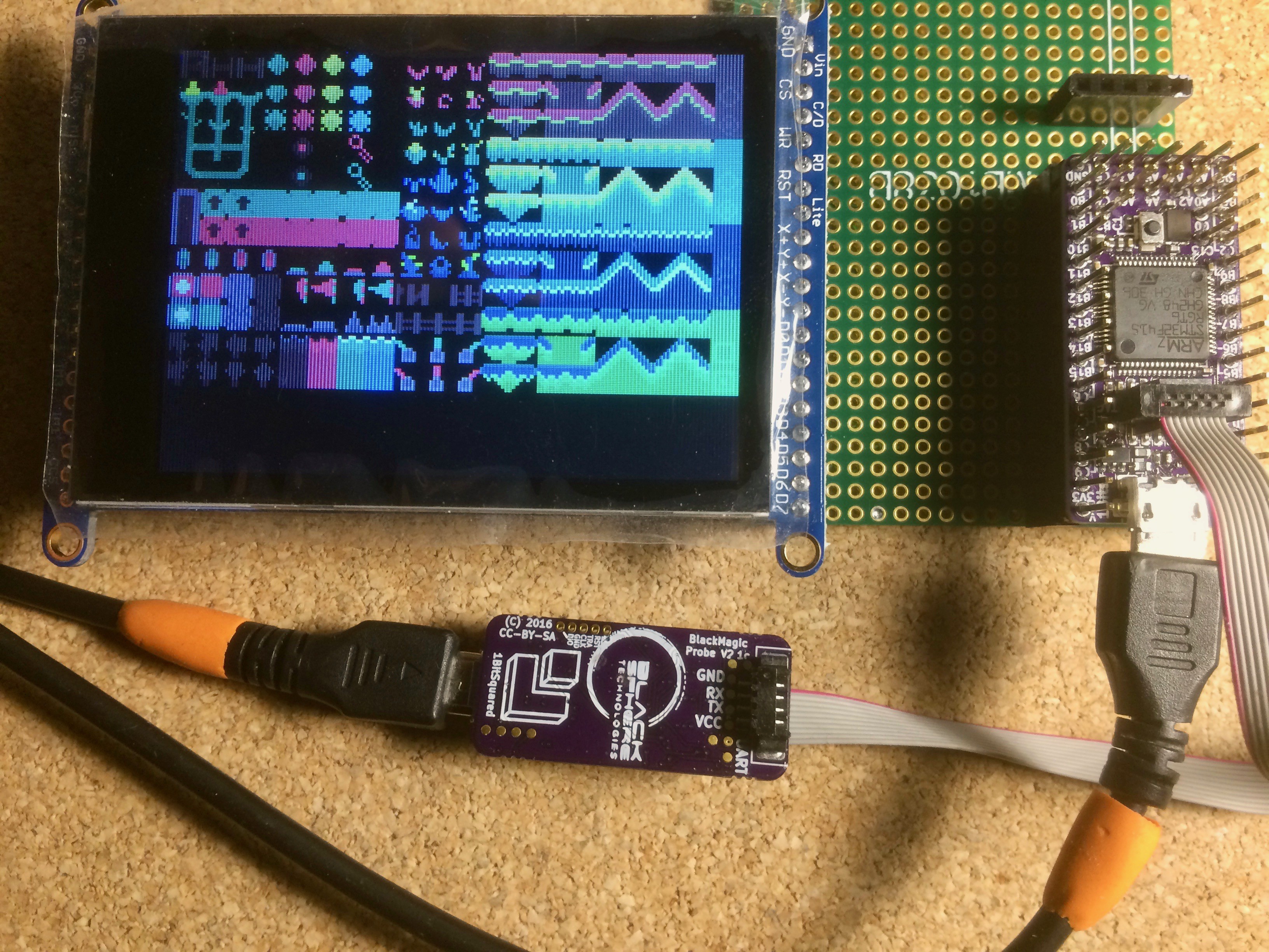
    Some more progress on the 1Bitsy 1UP firmware. Now that I managed to load some assets into the 1Bitsy I also have added a tile-map and implemented a simple rendering routine. I have also added a font to the assets and wrote a routine that is drawing the current frame-rate in the right upper corner of the display.

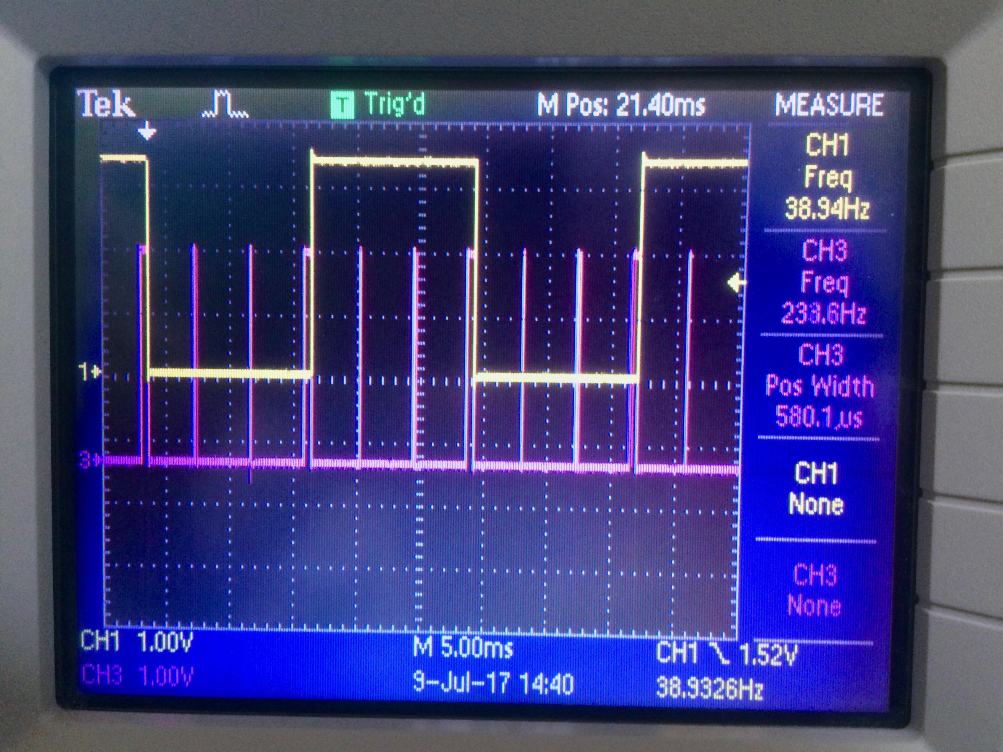
    I was reading out this variable in the past but it was in the range of 42 not 78fps... this caused quite a bit of consternation. I have now added some code that toggles a GPIO on each frame and my oscilloscope agrees that the frame-rate is indeed 78fps. Based on the parallel interface data rate the numbers agree: 12MHz byte clock -> 12MB/s data rate / 16bit/pixel (RGB565) -> 6MPixel/s / 320x240 -> 78.125fps I bet I was doing something wrong in the past and reading out a wrong value for the fps. It is really exciting to see that we are running almost at the internal LCD frame rate (we should be able to do TE signal sync! aka. VSYNC). While I was already at it I also added code that sets a GPIO hi when filling a pixslice with pixels. This indicates how much time we are spending with rendering of the picture within the frame time.

    The above picture shows the frame GPIO toggle (yellow trace, 38.94Hz = 77.88fps) and the time spent rendering the pixels. We obviously have a lot of time where the MCU is waiting for a pixslice to become available/scheduled. The STM32F4 does not stop to amaze me how fast it is! :D

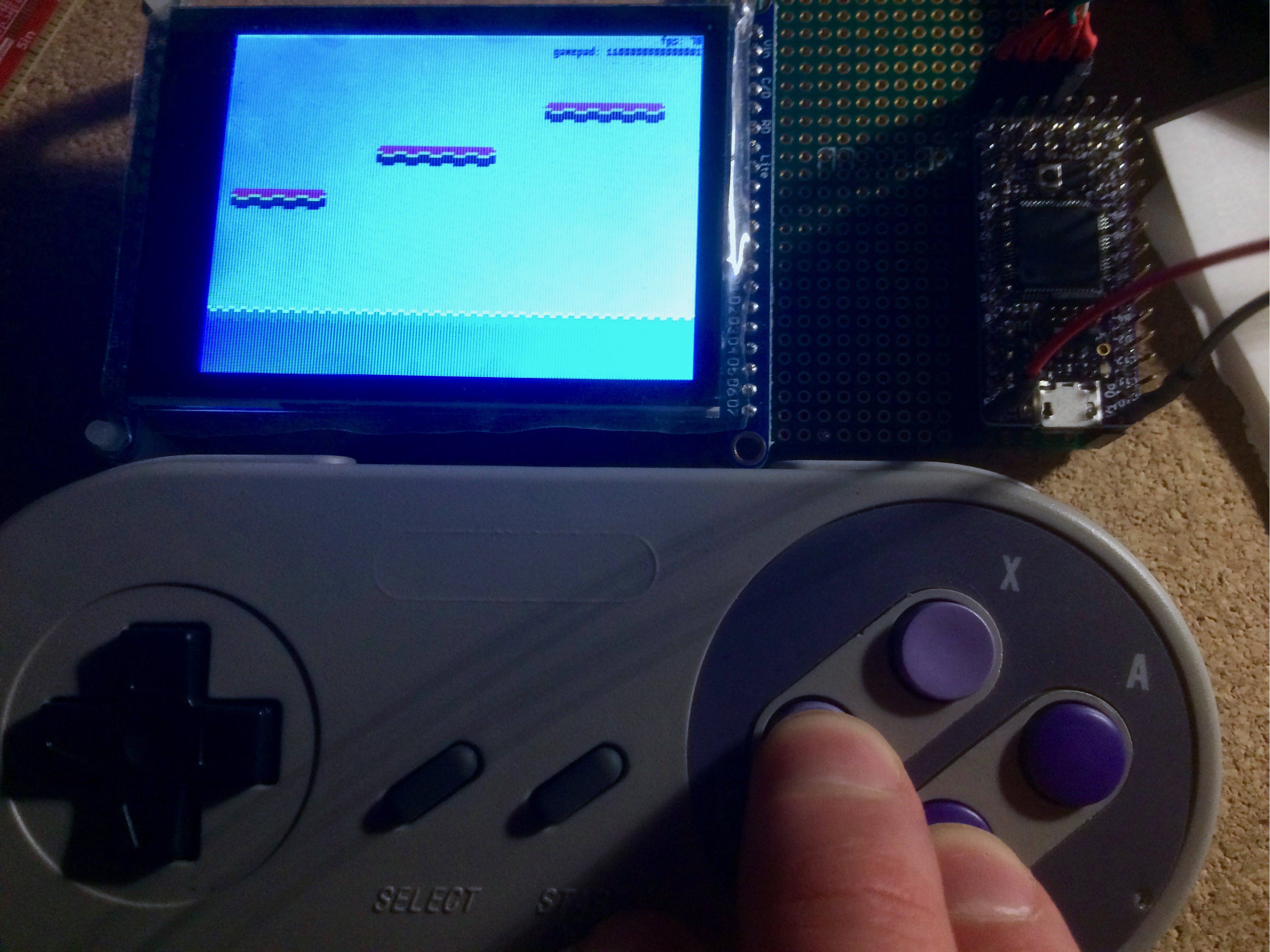
    As a next step I have added code to read out a gamepad shift register. The hardware that is in production at the moment has the same circuit as a SNES gamepad. This means two 8 bit parallel to serial shift registers. To be able to start writing some interactive code I have added a simple bitbang latch and clock out routine. I can now move the tilemap around using the D-Pad. I also added a small debug indicator showing 1's and 0's for all the shift register bits. Pressing any button will flip the corresponding bit on the display.

    This is all very good progress. In my opinion! ;D Still lot's of code needs to be written before we have something that resembles a console game, but that is part of the fun! :D

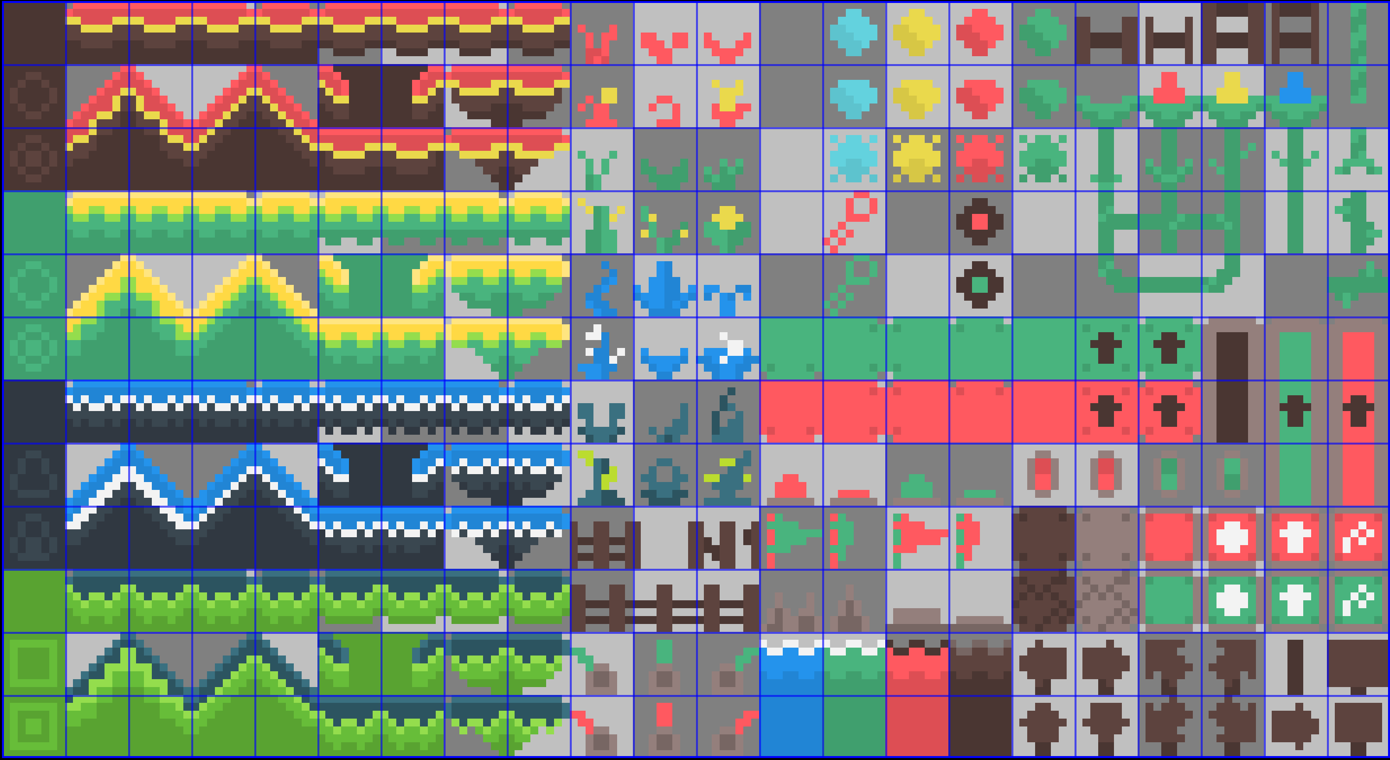
  • Tilesheet

    Piotr Esden-Tempski07/04/2017 at 22:17 0 comments

    I have started some work on the firmware for the 1Bitsy 1UP. Based on @Bob Miller's 1bitsy-lcd library I was able to start writing some code.

    It was mostly infrastructure work like copying bunch of dependencies, making them compile, renaming some terminology to work better down the road. (the structures we are holding pixels in that are passed to the DMA that is feeding the display are now called pixslices instead of pixtiles as we will have a bunch of actual "tile" code coming up soon)

    Now the firmware is displaying the mesmerizing munching squares eyecandy by default, and when you press the user button on the 1Bitsy it switches to the "tile_app" that will eventually become our tile based scroller game/engine.

    I had to spend a bunch of hours drawing the tilesheet too, I found some nice free tileset but it was way too high resolution and after scaling down to 8x8 pixel tiles it needed a bunch of cleanup.

    I am quite happy with the progress so far. But my day job is starting to catch up with me so I will probably have to take my foot off the gas pedal for a bit. :( I wish I could just continue cranking on this project until I run out of steam. :D

    I hope you like what you are seeing so far, I can't wait to see the final thing in action! :D

  • Back To Software

    Piotr Esden-Tempski07/02/2017 at 01:05 5 comments

    As the boards are now in production it is time to turn my attention back to some software. The boards will probably arrive here around July 17th so not much time for assembly and software writing between then and DefCon that is happening July 27th-30th.

    I had a test board for the 1Bitsy + LCD before but I gave it away to a potential project contributor, I have quickly soldered together another test setup last night.

    As you see, it is actually displaying some graphics already. The amazing @Bob Miller (aka. kbob / kernlbob) has already written a ton of driver code and demos for the 1Bitsy + LCD over parallel. The video might look familiar, this is what I have used in our Kickstarter video. :)

    I also got some other examples Bob wrote to run. The munching squares demo is really amazing, I love the effect and all it does is rotate the color palette.

    Now I am spending some time reading Bob's code and learning what changes and expansions I want to make to provide the type of interface and behavior we would expect on a retro inspired platform. This also means reading through the video subsystem specs of several 8bit handheld game consoles for inspiration. ;-)

  • PCBs Ordered

    Piotr Esden-Tempski06/30/2017 at 20:37 0 comments

    After review, a few minor tweaks and additional mounting holes added I have finally submitted the 1Bitsy 1UP PCBs to @oshpark.

    I really hope I did not make some major mistakes with the schematic. I have added a PDF export of the schematic to the project page here just in case anyone wants to review it. (if you find something do tell me in our gitter channel, but sadly because I have ordered the boards already I won't be able to do much about it now, besides bodge wires if possible)

    I got some really good input from twitter, to add a back plate to the board to provide thickness and a good grip. That was a marvelous idea, so I went ahead and added a few m3 holes for PCB standoffs. I have some standoffs in white nylon but I think I need to get my hands on black ones, unfortunately I don't think they make them in purple unless I get aluminium standoffs that are purple anodized but as far as I remember that purple is usually quite unpleasant. :)

    All in all, we have very good progress on the project! Can't wait to get the boards back. I probably should place the order for the massive DigiKey cart that has drown over the course of this project. :D

  • Finished Routing

    Piotr Esden-Tempski06/30/2017 at 09:52 0 comments

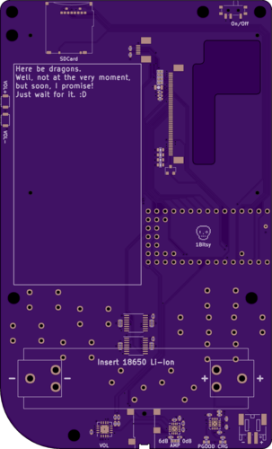
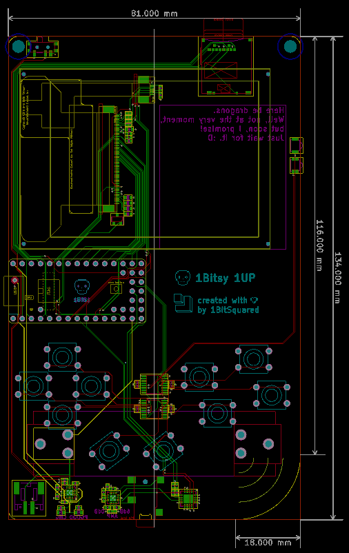
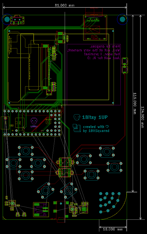
    I have just finished routing the 1UP board V0.1. I am quite happy with it. It is the most spacious board I have ever had to route. I spent some time trying to tidy up the traces. Unfortunately because the stuff is so far apart the traces become a bit like tendrils. :)

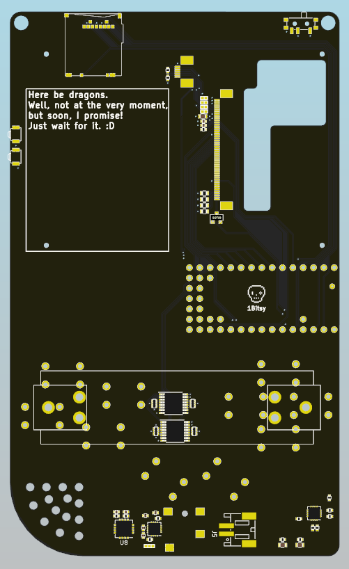
    We have quite a lot of space left on the back side of the board for the future expansion that I have in mind. This is very exciting.

    I wish I had more of the 3d models to put onto the rendering. This would give me more confidence about the design. Unfortunately I don't think I have the time to put together the 3d models. Maybe some time down the road I will do that just for fun, but now I really need to get the board out to @oshpark.

    I have also cleaned up and finished up the schematic. While doing that I realized I could have sprinkled on a few more decoupling caps, so I did. :)

    I will have to sleep over it but I think we are ready to roll! :)

  • Routing in Progress

    Piotr Esden-Tempski06/29/2017 at 21:29 0 comments

    A quick update. I am almost done with routing of the board. Audio amplifier/volume control and battery charging/powepath circuits are left. Still thinking about the best way of laying out both of them.

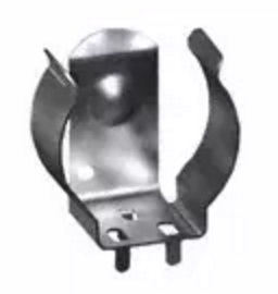
    Battery circuit needs some decisions regarding the battery form factor, position, connector position. I think I have settled to put a JST connector on the board as well as footprints for 18650 clips. I have done some paper based physical tests, they look good and I think the 18650 solution is the way to go.

    Here are the 18650 clips that keep the battery away from the PCB allowing for parts under the battery. But if you look at the design above, it will be fun to file down the solder points of the battery contacts to allow the gamepad buttons to go flush against the board. I think I will have to considery relocating the battery. The problem is that I want it to feel good when you hold it, even without a case.


    Regarding audio, I have not decided if I want to run the amplified signal or the source signal half across the PCB. The board is a 4layer board so I should be able to achieve some good signal integrity, but I am not 100% convinced which one is the right approach. I probably will just go with my gut feeling and see how that works out. I can always change it in the next revision of the board. (TM) :D

    Something that I have not mentioned before, I am planning to have the board finished before DefCon 25 (Jul 27, 2017 – Jul 30, 2017) and if it actually works and displays something I might even be proud enough to wear it on my neck as my personal badge. (this is what the 3mm holes on the top corners of the board are) :D

    So if you are at DefCon and you see a dude with a strange badge that looks like a handheld game console from the 90ties and a 1BitSquared or 1Bitsy T-Shirt make sure to say hi.

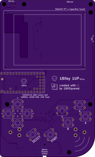
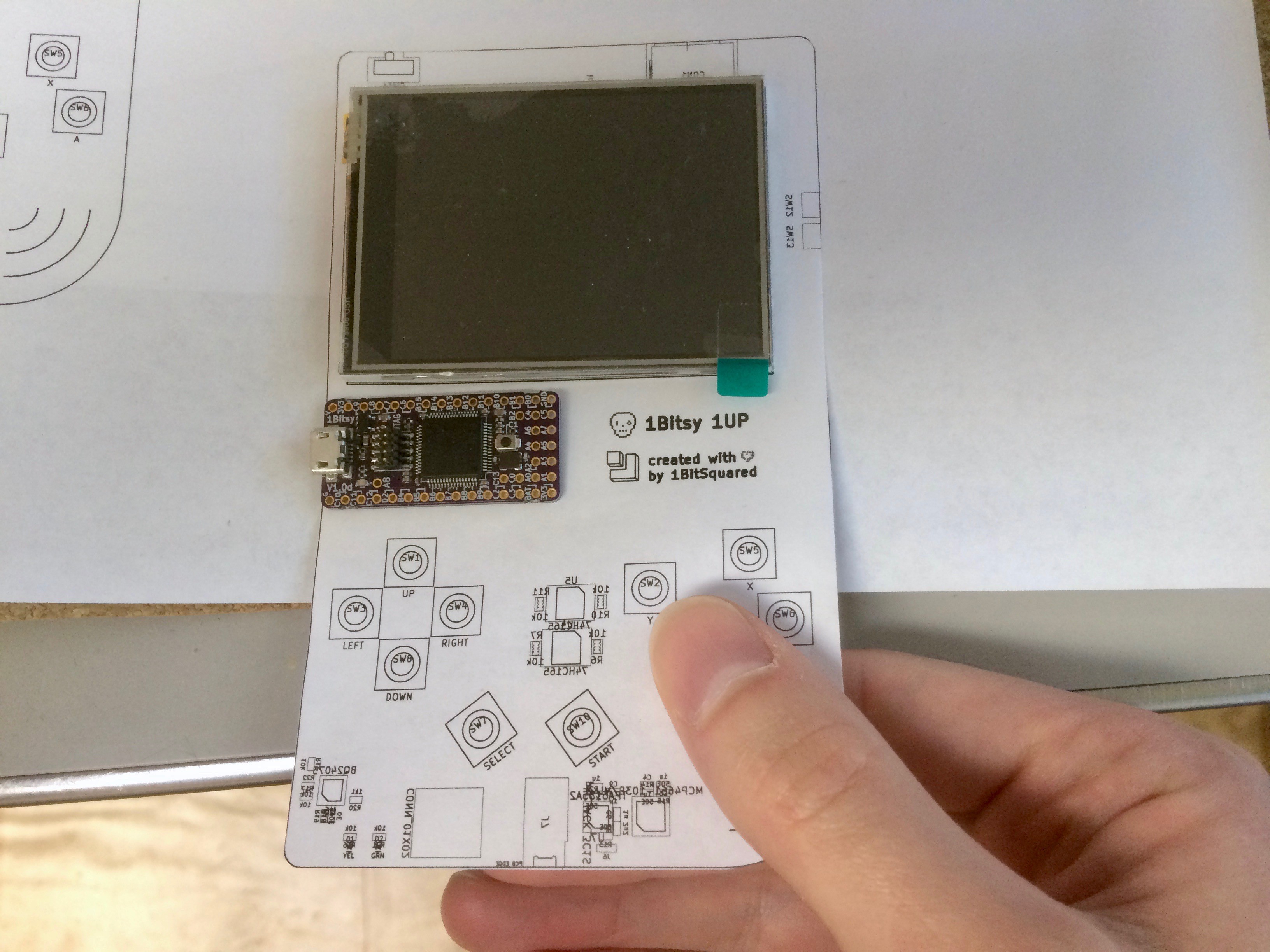
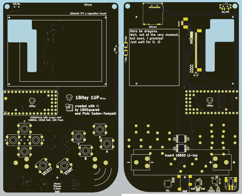
    Last but not least. I have printed out the board artwork to get a feel for the size of the board. Here is what came out of that.

    I have to say I am quite excited about where this project is going. I see lot's of software writing in my near future, as soon as this board is submitted to OSHPark that is. :D

View all 12 project logs

Enjoy this project?

Share

Discussions

fabian wrote 07/19/2018 at 14:07 point

Czy to zadziałało by z NanoPi ? Trochę lepszy system i więcej pamięci.

(it will be works with nanopi?)

  Are you sure? yes | no

Martin Cejp wrote 04/20/2018 at 06:20 point

Why would you use such an expensive MCU for a 2D hobby handheld?

  Are you sure? yes | no

Piotr Esden-Tempski wrote 04/20/2018 at 06:48 point
Are you serious? Why would you ask such a question? It is similar to: "Why would you use a computer to write a letter instead of a typewriter?"

  Are you sure? yes | no

deʃhipu wrote 12/09/2017 at 14:44 point

Hi, it has been a while since the hardware is finished, did you manage to write any game for this console?

  Are you sure? yes | no

Piotr Esden-Tempski wrote 04/20/2018 at 06:50 point
Sorry for the delayed answer. We have some software written for the platform. But we went back to the drawing board and are working on a new revision of the hardware, so the software work is rather slow. :D

  Are you sure? yes | no

Similar Projects

Does this project spark your interest?

Become a member to follow this project and never miss any updates