Close
0%
0%

RGB LED fading

fading with a PIC12F508

Similar projects worth following

This is a simple RGB fading. It looks like this:

The circuit:
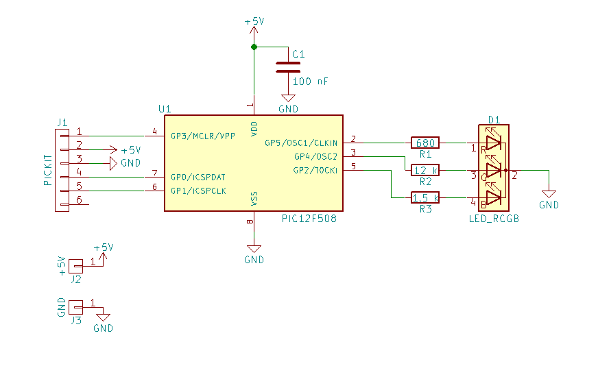
This is the C source code for the XC8 compiler, for MPLAB X:

// simple RGB LED color fading

// PIC12F508 Configuration Bit Settings

// 'C' source line config statements

// CONFIG
#pragma config OSC = IntRC      // Oscillator Selection bits (internal RC oscillator)
#pragma config WDT = OFF        // Watchdog Timer Enable bit (WDT disabled)
#pragma config CP = OFF         // Code Protection bit (Code protection off)
#pragma config MCLRE = OFF      // GP3/MCLR Pin Function Select bit (GP3/MCLR pin function is digital input, MCLR internally tied to VDD)

// #pragma config statements should precede project file includes.
// Use project enums instead of #define for ON and OFF.

#include <xc.h>

#include <stdint.h>

#define RED 0b00100000
#define GREEN 0b00010000
#define BLUE 0b00000100

// global variables need less memory
uint8_t redPwm;
uint8_t greenPwm;
uint8_t bluePwm;
uint8_t out;
uint8_t i;
uint8_t j;
uint8_t k;

void cycle()
{
    // adjust number of cycles for fading speed
    for (k = 0; k < 5; k++) {
        for (i = 0; i < 255; i++) {
            out = 0;
            if (redPwm > i) out |= RED;
            if (greenPwm > i) out |= GREEN;
            if (bluePwm > i) out |= BLUE;
            GPIO = out;
        }
    }
}

int main()
{
    // configure pin 2, 4 and 5 as output
    TRISGPIO = 0b11001011;
    
    // default value of T0CS overrides the TRIS function, which makes GP2 an
    // input for the timer, disable this to make it an output,
    // and disable all pullups
    OPTION = 0b11000000;
    
    // fading algorithm
    while (1) {
        // blue to red
        for (j = 0; j < 255; j++) {
            bluePwm = 255 - j;
            redPwm = j;
            cycle();
        }
        cycle();

        // red to green
        for (j = 0; j < 255; j++) {
            redPwm = 255 - j;
            greenPwm = j;
            cycle();
        }
        cycle();

        // green to blue
        for (j = 0; j < 255; j++) {
            greenPwm = 255 - j;
            bluePwm = j;
            cycle();
        }
        cycle();
    }

    return 0;
}
Full project files and KiCAD circuit is in the zip file.

color-led.zip

MPLAB X project with source code, and KiCAD schematic and board.

Zip Archive - 1.02 MB - 06/28/2017 at 23:07

Download

View all 7 components

  • recording with filter and ideas for improvement

    Frank Buss06/29/2017 at 08:20 0 comments

    Same setup, recorded with my Canon camera and a ND64 filter:There are some visible problems. First the brightness doesn't change logarithmically. This results in less perfect color blending, because there should be more brightness steps when it is darker. Second problem is that you can see the brightness steps, if you look carefully. This would require a finer PWM resolution, currently I use 8 bit. I don't know if I can fix both with the PIC, with 512 words flash and clocked at 4 MHz it is a bit slow, but maybe it is possible when I write it in assembler instead of C.

View project log

Enjoy this project?

Share

Discussions

Andrew Sowa wrote 06/29/2017 at 18:20 point

void dither(int x){

      Serial.print("  R:");
      Serial.print(red);
      Serial.print("  G:");
      Serial.print(green);
      Serial.print("  B:");
      Serial.println(blue);
     
      
     for(int i = 1; i < x; i = i+3){

        analogWrite(9, red);
        analogWrite(10, green);
        analogWrite(11, blue);
        delayMicroseconds(i);
        analogWrite(9, redOld);
        analogWrite(10, greenOld);
        analogWrite(11, blueOld);
        delayMicroseconds(x-i);
      }
      
      analogWrite(9, red);
      analogWrite(10, green);
      analogWrite(11, blue);
  
}

  Are you sure? yes | no

Andrew Sowa wrote 06/29/2017 at 18:16 point

You can get more levels on a 8 bit by varying the time between two states.  Your eye will integrate the change and make it look cleaner.  I call it dithering but I am not sure if dithering is suppose to only refer to a 2D map.   For example your start the led at 254 2khz pwm.  You then add in 253 pwm and alternate between those two at a lower frequency.  If you do this at equal rates your eye will think there is a brightness level between 254 and 253.  It won't be seen as halfway because perceived brightness is complex but it will be less than 254 and greater than 253. 

I had trouble doing this smoothly with a 16mhz arduino because it would occasion delay enough to flicker.  Throwing a teensy solved it but I may have been able to solve it with better software.  

I think they talk about this in the podcast below.  I don't have time to re-listen to it to confirm. 

http://embedded.fm/episodes/2014/3/4/41-pink-universes-die-really-quickly

  Are you sure? yes | no

Frank Buss wrote 06/29/2017 at 19:46 point

Thanks, dithering looks interesting, if you just have 8 bits. But I think I'll use a different PIC, the PIC12F1572, which is pin compatible (good about PICs: they are nearly all pin compatible more or less, if you chose a type with the same number of pins) and which has three 16 bit PWM channels, and an internal 1% accurate 32 MHz clock. Only downside is that it costs EUR 0.55 instead of EUR 0.46, like the PIC12F508, but would be still cheap enough for an advanced LED throwie :-)

I've read some studies and done some tests about PWM LED control, and implemented a 13 bit PWM with a FPGA (hugely overdesigned, 30 PWM channels, with additional individual phase-shift ability and 25 MHz clock, just for fun). Result: 12 bit is still good, which would result in a PWM frequency of about 8 kHz for 32 kHz clock, which is above the lower limit of 3 kHz, which some people can see as flickering, if they move their eyes fast. Details see here:

https://hackaday.io/project/20474-antique-nixie-clock/log/56827-pwm-test

  Are you sure? yes | no

oshpark wrote 06/29/2017 at 17:55 point

Looks great!

(check it out @Andrew Sowa)

  Are you sure? yes | no

Similar Projects

Does this project spark your interest?

Become a member to follow this project and never miss any updates