 Shulie Tornel
Looking to couple a low cost wireless position sensor with hand-held ultrasonic testing (UT) inspection units to make inspections faster, more accurate and safer.
Position Sensor Specifications:
-A wireless sensor unit (the beacon units, if any, may be wired, but wireless beacon units are preferred);
-A sensor having coverage of, at a minimum 1meter x 1meter projected on to the surface of a pipe that can range in diameters from 1inch to 36inches;
While 1meter x 1meter is a minimum requirement – any prediction/calculation of largest possible scan area without loss in resolution would be appreciated.
-A sensor that detects linear position in x, y, and z directions with a linear resolution of 1mm x 1mm x 1mm and detects angular deflection in its plane from a nominal, pre-defined vertical line with an angular resolution of 10;
-A system capable of being implemented on pipes with diameters ranging from 1inch to 36inches;
You may choose to design for a nominal pipe diameter of 12 inches but the physics of the system should work for the entire range above. Specifically, the system must be trivially modifiable, in construction alone, to fit the entire range of pipe diameters.
The system must be operable on pipes that are unsupported at heights of 1-30m above ground.
Again, you may choose to design for a nominal height of 10m above ground. However, the physics of the proposed system should not be limited by the height of the pipe above ground.
-The system should work on pipe surfaces that curve with a curve radii ranging from 1.5 to 2 times the OD of the pipe.
A system that is modifiable for all clearances from 150mm to 600mm but may be designed for a nominal clearance of 300mm. This clearance is defined as the distance from the outer surface of the pipe to the nearest structure;
-A sensor unit that is smaller than the probe unit (20mm by 50mm.);
-A system that returns the position information via either a I2C bus (preferred, outputting the absolute position as a 4-count) or another connection with an update rate of not less than 50Hz;
OK -- here is the bio... I am the Technology Leader at Fuse. I got my B/M Tech. from India and my Ph.D from Michigan State (go green) ...Prior to joining GE, I was a Research and Development Manager at Ansys Inc., I like to ride reining horses ...
Sure @Sophi Kravitz ! Hello! I am a Community Manager of GE Fuse, an team within GE that works on specific product and technology challenges via open innovation/crowdsourcing. So every technology challenge we try to solve comes with prize money, potential partnerships, joint development opportunities, etc. (For personal background I come from a Chem Eng background, but have been hanging with people who build hardware, so I'm learning my way around.)
+1 on Kalman filters ... I thought they could be put on chip ??? no ?
isn't magdwick better?
@naveen.nair Sure, but the specific setup I was looking at literally didn't fit on the flash storage we had haha.
Well... I have Magdwick too in Visuino for that matter... ;-)
http://x-io.co.uk/open-source-imu-and-ahrs-algorithms/

Open source IMU and AHRS algorithms
In 2009 Sebastian Madgwick developed an IMU and AHRS sensor fusion algorithm as part of his Ph.D research at the University of Bristol. The algorithm was posted on Google Code with IMU, AHRS and camera stabilisation application demo videos on YouTube. The algorithm received thousands of downloads but the code project was never maintained or updated.
may come in handy
They seem to take few hundred bytes if I recall... based on the controller etc.
GPS ICs run pretty intense kalmans but im sure they are implemented in hardware ;-)
Always FPGAs...
@Radomir Dopieralski --- thanks ! I did look at this (came on the same search for IMU registration algorithms ) ... but am not sure if this will be enough ...
Ideally would need a reference to a SECOND absolute velocity measurement - then we can correct for velocity, and then integrate the position to avoid the drift... I think ...
not sure if that would work ... any ideas ?
At least part of the drift is just from sampling rate, right? BNO does 100Hz, which leaves gaps for data to fall through.
yeah ... true.... higher sampling rate would allow for smaller drift --- I saw this one occulus rift video online where the drift blew up in seconds... was scary !
Dang
that said though ... even if we have a position sensor there are other interesting challenges to solve -- I mean for example, what would we do with the position information ...
So what we know so far is that you're interested in getting pretty precise positioning around metal tubes.. Any other information that might help? Is this setup indoors and somewhere that can have scaffolding around it?
say we collect position at 100Hz... UT data comes in around 1KHz. ... how do we register one with the other...
what kind of radial resolution do you need around the ID of this pipe?
like, are you trying to create an image of the inside of this thing?
(image -> 3d model)
@ctag@Daniel S. 1. it will have scaffolding around it 2. we are NOT looking for ID information .. just position on the OD.
Cool
Maybe a vision based setup is worthwhile?
think of it as a sheet of paper 1m x 1m wrapped around the pipe -- now we want to know where on that sheet we are .. within a 1mm accuracy .
Man i am totally reading those specs wrong
@ctag --- interesting you mention it... someone once asked me if we couldn't just mount a kinect on a helmet.
haha
Maybe a littler better than that
it is certainly a viable argument though ... I don't have the faintest idea if there is precision/resolution data on a kinect system though...
@ctag Since you asked about scaffolding, the system must be operable on pipes that are unsupported at heights of 1-30m above ground.
@Daniel S. -- let me know if i can help you with wading through the specs...
I get the feeling this is a job for something like the sensor inside an optical mouse, only for absolute positioning instead of relative... which is really just a software task
@Daniel S. -- it is not necessarily a bad idea -
glue some magnets to a high-res mouse and throw it on the pipe, marking your landing point as index 0,0,0
then its all software, no? am i missing something
simple solution
If you think about it -- an optical mouse is really a position sensor ... that said though, several questions arise right -- how do we handle the pipe material and the angle of the bend .. ?
scrolling up is a pain, whats the min radius bend?
oh right... you have really small OD pipes
meh.... typically all O&G pipes stay in the 1.5D to 2.0D range... .
so an actual mouse might be tricky
D = OD of pipe
thats not that intense, until you talk about a 1" pipe and a 2" radius
ty
:) ... yeah ... .honestly though getting around that bend is our only problem ... Ill buy the first beer.
*if
hmm... gut a really small mouse and repackage it =)
ive done that for a couple projects
3d mouse?
@morganrallen and @everyone really we don't need 3D ...
you know, I have this fantasy since a while -- remember those pens at the post office that have a fancy chain attached to them?
make a chain like that, but but an encoder in every link
*mind blown*
mega faro-arm
we only need 3-D in the limited sense that it is a 2-D surface wrapped around a 3-D object --- the really topologically inclined among us will call it a manifold.
wow
of course it would need to be super-accurate
yeah its totally just a 2d problem. only 3d because we are in meatspace.
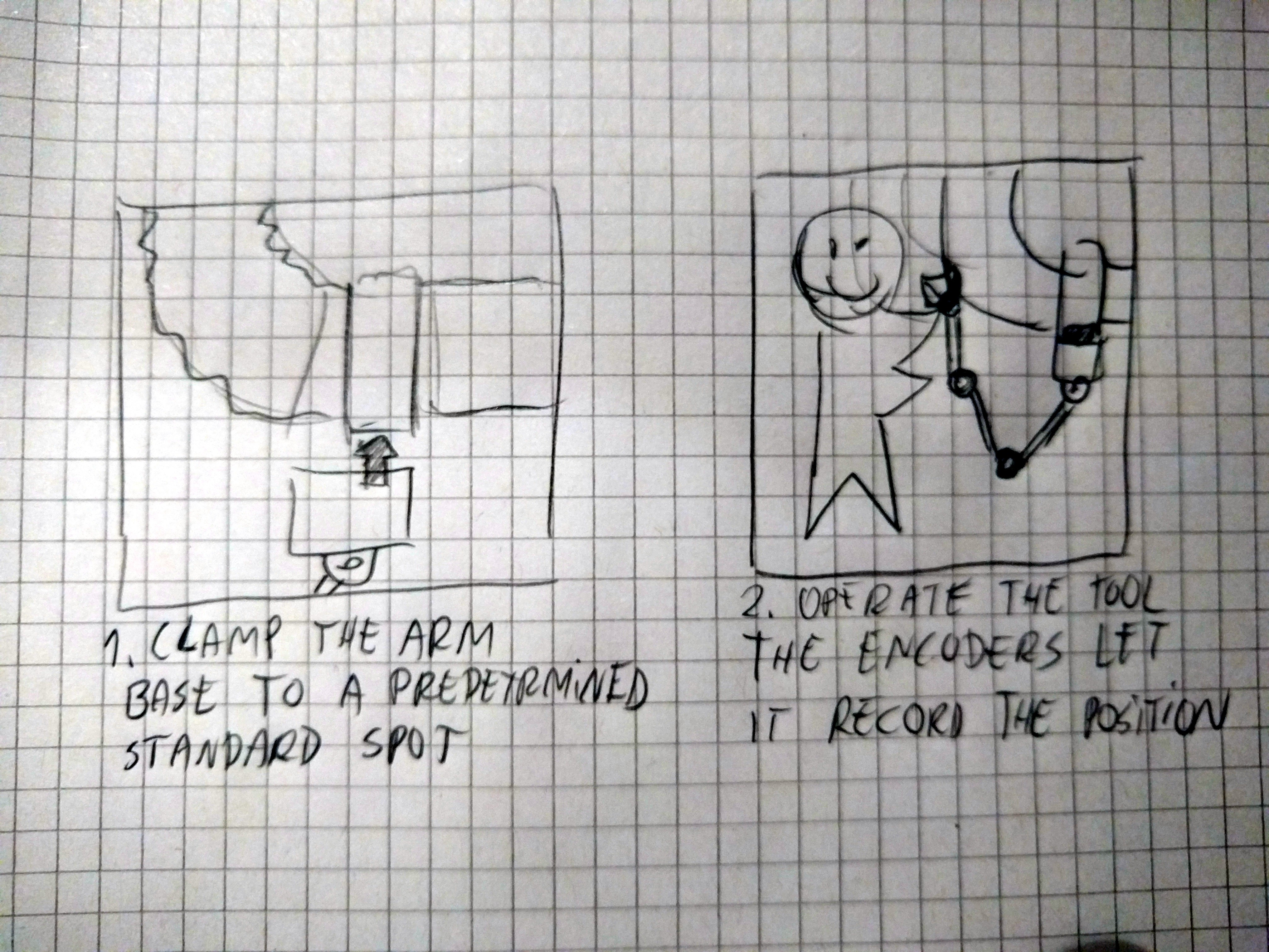
yeah -- here is a clunky system idea that almost certainly will work .. if there are any unclunkers among us ...
what's the surface made of? can you put a pattern on it?
I may sound stupid, but what about a rotating precise laser ranger?
or project a pattern on it
Loading image…
take 3 optical encoders and attach them to three movable arms in x y and z., create a concentric frame around the pipe and go scan away ...

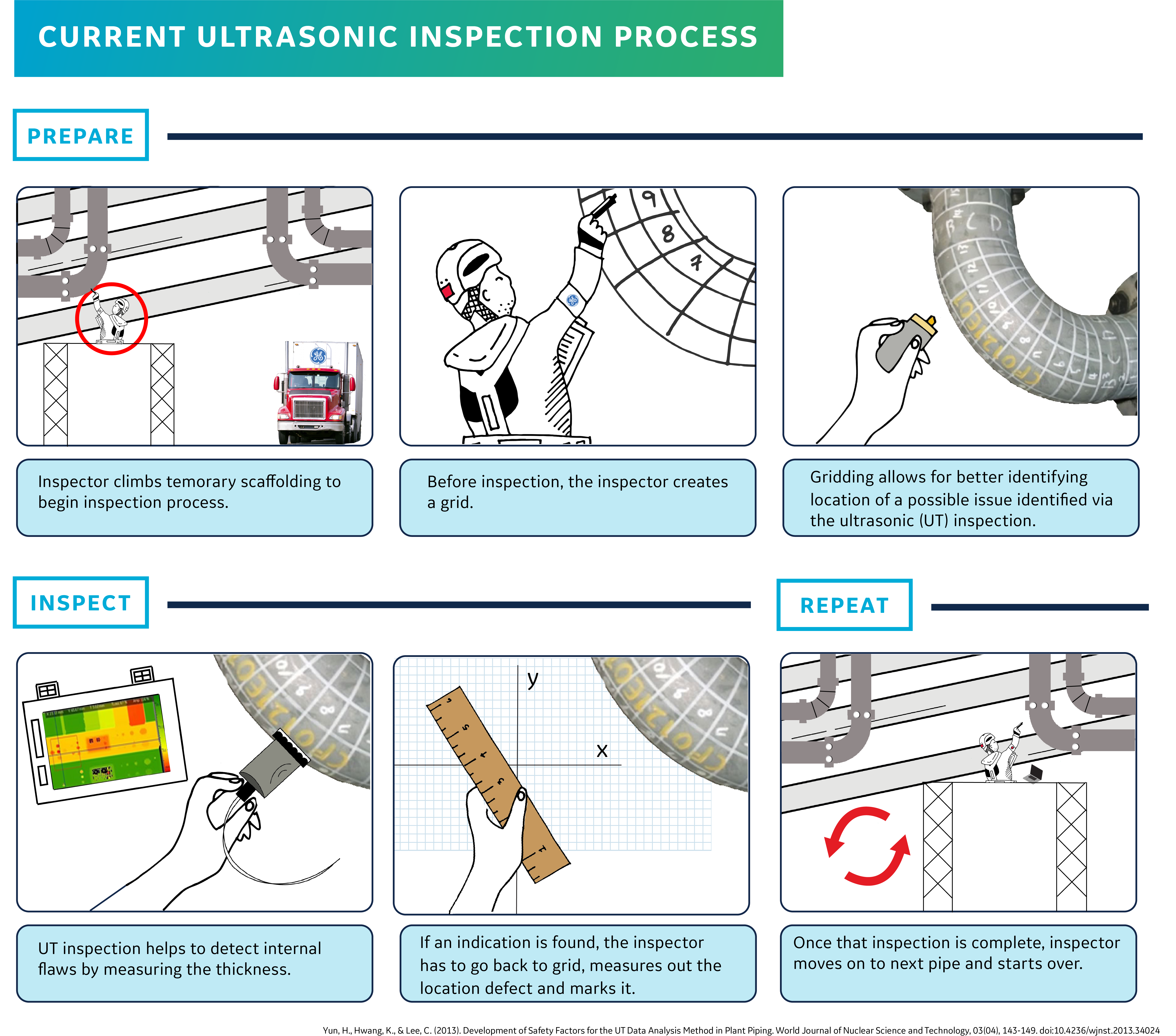
@Radomir Dopieralski funny you should ask...the current process is like the pic I just posted.
@Radomir Dopieralski we can certainly project a pattern ..
So is the problem the calculation of sensor position, or the precision of the surface sensor ?
@Boian Mitov - not sure what you mean , sorry -- we need calculation of the sensor position ... @Amelia meant that today the operator literally hand draws a grid on the pipe
and then hand places the instrument in each grid ... the "old" way of measuring position :)
So the sensors are on the outside of the pipes ?
@Radomir Dopieralski --- i like where you are going -- are you suggesting a mouse like idea where we project a pattern and then count it using a sensor ..
@Boian Mitov -- yes ..
hang on .. let me see if I can pull in a pic..
Then there are some solutions for 3D positioning based on multiple transmitters positioned around the area. Something like this may work
You position few transmitters at known location and triangulate from them
@Boian -- yes !!!
I think that would indeed work ... a local GPS ... .
(VERY) local...
yes
do you guys know if something like that exists ?
Somebody even did a Kickstarter robot project with something like this a year or 2 ago
@naveen.nair I really have no idea, I'm just trying to see what's possible. So far I like the idea of a robot-like arm with encoders the best.
Position light beacons outside the area and have the inspection device look *out* to them. Like astrophotographic plate-solving.
not sure if it got funded, but they had fairly precise positioning
@naveen.nair it could really be super-precise
like this: https://www.pozyx.io/
Accuracy would be a pain though
Yes, I think https://www.pozyx.io/ was the project
Esp if the beacons aren't permanently mounted.
older 3d scanners use "positioning dots" placed on objects in a random pattern, then the 3d scanner would observe the pattern of the dots and triangulate its position in space based on visible dots
@Ctag --- remember our competition is a tired and irritated operator taking a piece of chalk and drawing a grid on a pipe -- thats a pretty low bar... so if we can install the beacons in like 10 minutes or so they might go for it.
Pozyx is an UWB (ultra wide band) positioning system (i.e. indoor gps) - they are not very new but it was meant to be more attainable than the multi thousand dollar commercial versions. So far as I know UWB is in the 1-10cm accuracy range at the very best.
@Jordan Bunker, kinda what I'm thinking of but maybe the dots are external and mounted in a known orientation.
Looks like we are coming up on the end of the 30 min (but @naveen.nair seems up for continuing to go on so I won't stop you). I supposed I should not withhold the information on the full challenge and potential prizes. We've got all the challenge details here and some discussion topics going here: https://launchforth.io/fuse/position-sensor-design-challenge/brief/
@Shantam Raj : may be the plastic cap kind of mechanism which is found in automotive ECU's, sorry dont know the exact name of that part.
@BrendanMatkin --- I am wondering if we can go lower in bandwidth and gain positional resolution .
@Sujith Anandan ---I am a little lost ---ok .. very lost ... could you elaborate ?
@naveen.nair Possibly - they are designed for warehouse-scale tracking
You can use higher frequency, if you can get permit etc. But you will lose some penetration
we are in air -- and we only need a "m" of range so we should be able to do something ... again ... worried about all those pesky iron pipes in the vicinity !
With enough transmitters you may be fine
@Will Kalman What we used to do at the lab is set up a "stage" with dots already on it, and place the object in the stage
Why not just wrap a sheet of encoded plastic around and use a visual scanner like those use in livescribe-like systems?
basically a bunch of QR-codes in a giant array
@Will Kalman Could do the same with a pipe, and just magnet/strap the backdrop to the pipe
We're going to start wrapping it up
So get your last thoughts in now :)
@BrendanMatkin -- That is a cool idea-- .
then the operator could wear a camera that views the dots, the ultrasonic sensor would also have dots on it, and the whole system could view the difference in dot movement to triangulate position
@Radomir Dopieralski -- yeah this could work ...
@Jordan Bunker isn't there a hand router that does that?
with a fiducial tape
thanks @naveen.nair !
I am going to see if I can put together a few small experiments to see if some of these ideas can work ...
yep, that relatively new one
http://hackaday.com/2016/05/20/shaper-tools-will-blow-your-mind/
Shaper Tools Will Blow Your Mind
Have you ever wanted to own a full-sized ShopBot? What if some geniuses somewhere made a tool the size of a coffee maker that had the same capabilities? Does an augmented reality, real-time feedback, interactive, handheld CNC router that can make objects ranging in size from a pillbox to an entire conference room table sound like a thing that even exists?
Shaper Router
@Radomir Dopieralski yeah it uses tape
it's a pretty robust way of determining position, and old
similar to what I was describing with the livescribe thing
@Sophi -- thank you so much --- those 30 minutes went by quickly ...
you just stick some adhesive tape on it
Naveen, can you post the result from your experimentations on the event page? https://hackaday.io/event/25727-design-slam-hack-chat
absolutely --- it will be a couple of weeks but I certainly will
Anyone doing experiments on this, please post to the event page or to the challenge https://launchforth.io/fuse/position-sensor-design-challenge/brief/ itself
In place of fiducial tape and potential difficulties with resolution and clarity, You can use a known random pattern of dots and pattern-solve.
Thanks to @Amelia as well!
@Will Kalman +1
@Will Kalman +1 that's how the 3d scanners do it
You could actually combine the system with a white-light scanner (would be big though) and then have a 3d model output with the measured densities
We do it to determine telescope orientation to arc-minute accuracy astrophotograhy using catalogs of known star locations.
Discussions
Become a Hackaday.io Member
Create an account to leave a comment. Already have an account? Log In.