Here are the pictures I mentioned in the first two logs. These are also included as files.
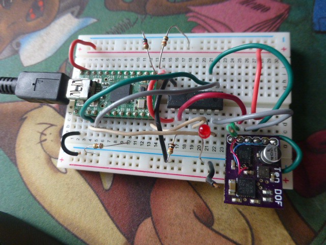
Experimental Breadboard showing Teensy2, ATTINY84, and the IMU.
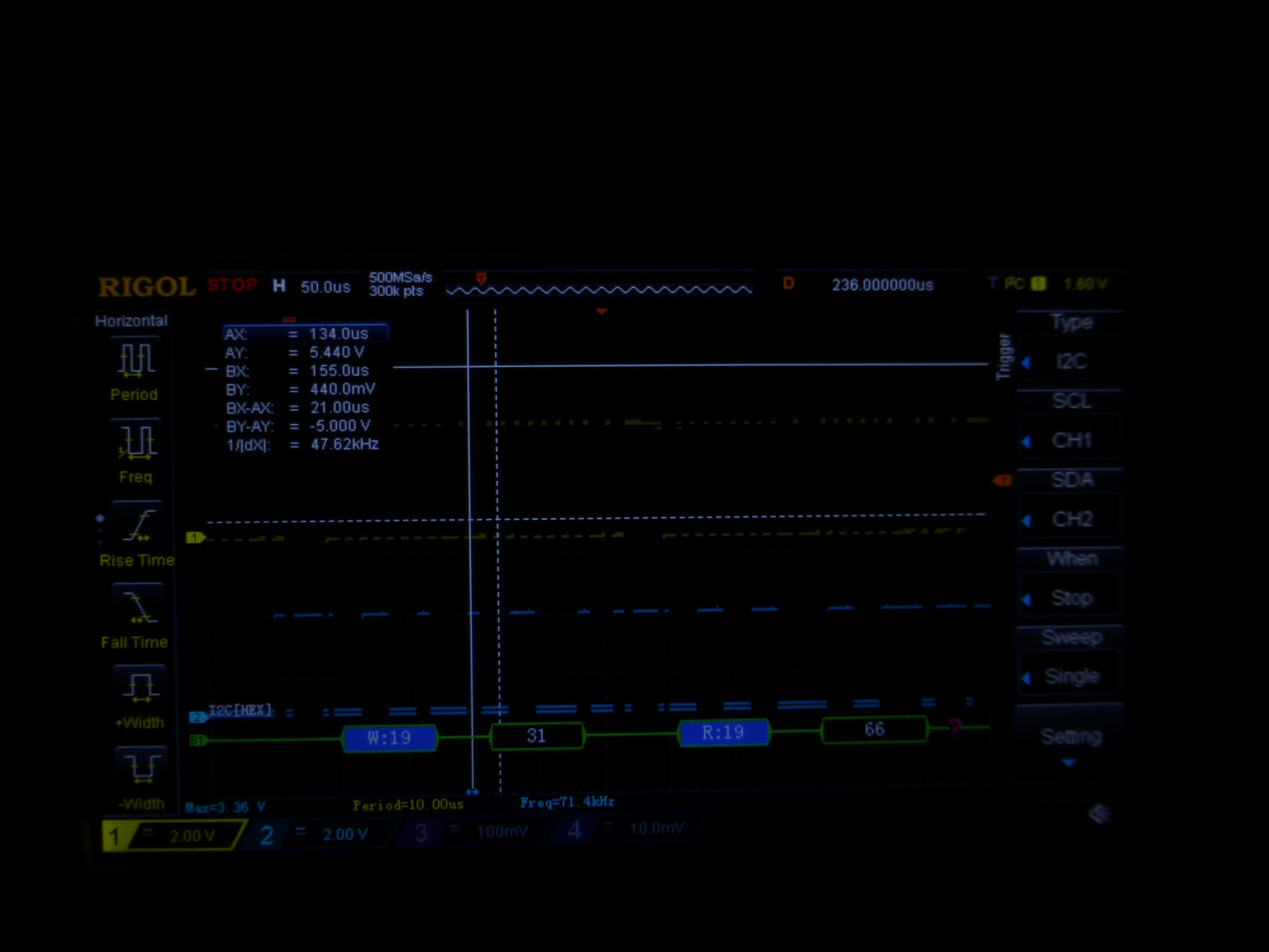
Rigol Scope I2C Capture and Decode.
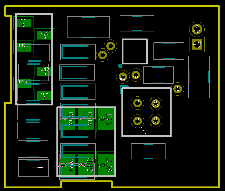
Connector Board Design and Schematic. This shows the pad footprints that are on the back side of the POV board. The locating notches are shown in the board outline.
 This is the board design for the 2x3 uProgrammer. All it does is carry the contactor and provide connection points.
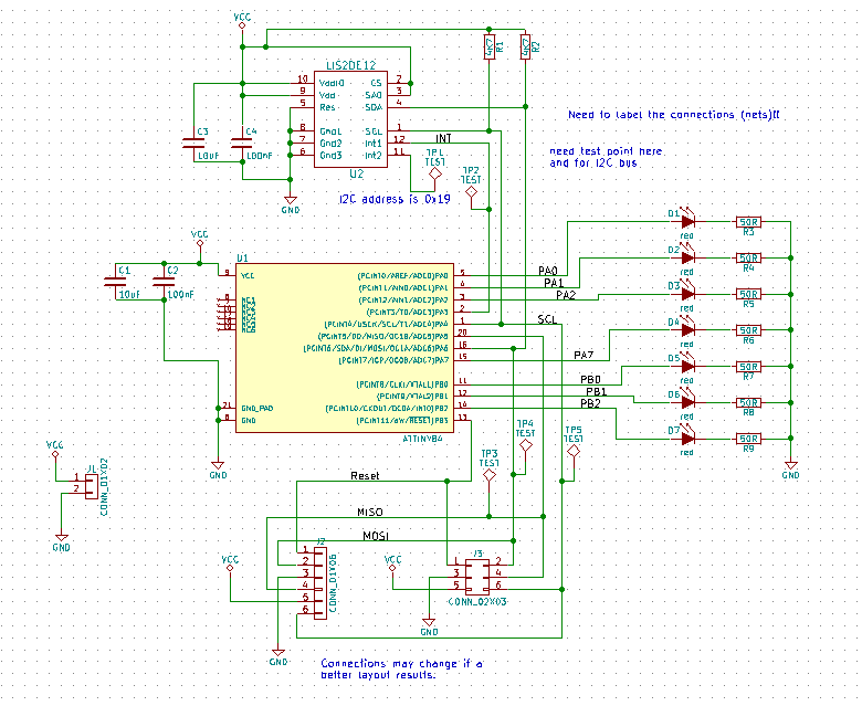
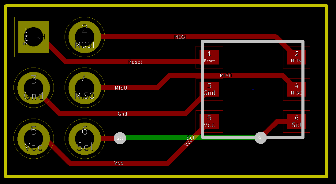 This shows how the uProgrammer pads are included in the schematic.
 doctek
Discussions
Become a Hackaday.io Member
Create an account to leave a comment. Already have an account? Log In.