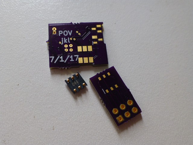
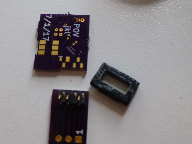
A short aside here to discuss the uProgrammer. In the last post, I kind of brushed over the uProgrammer, although it was an area I was very worried about. If it hadn't worked, the whole project would have been a Fail-of-the-Week! The concept was discussed in the Circuit Board and Programmer Project Log, but now that I know it works, I can talk about the implementation. The idea was to use a spring contactor to provide the connection to the board with the microprocessor on it. A footprint for the contactor contacts to hit was included in the microprocessor board design. As previously mentioned, a frame was 3D printed to provide the spacing between the contactor and the footprint so the contactor could be reused.A small notch in the board mates with a tab on the frame for easy alignment. These pictures should help you to get the idea.


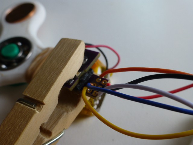
This scheme turned out to work really well! A clothes pin works as a clamp to hold the microprocessor board and the uProgrammer together.

Since this approach allows building very small "Arduinos", it may be the most useful part of this project.
 doctek
Discussions
Become a Hackaday.io Member
Create an account to leave a comment. Already have an account? Log In.