 Arcadia Labs
The robot's frame and accessories parts are full 3D designed and printed. I wanted the robot to be very modular, and easy to customize and repair.
3D STL files are located here : https://github.com/CaptainStouf/balancing_robot/tree/master/STL
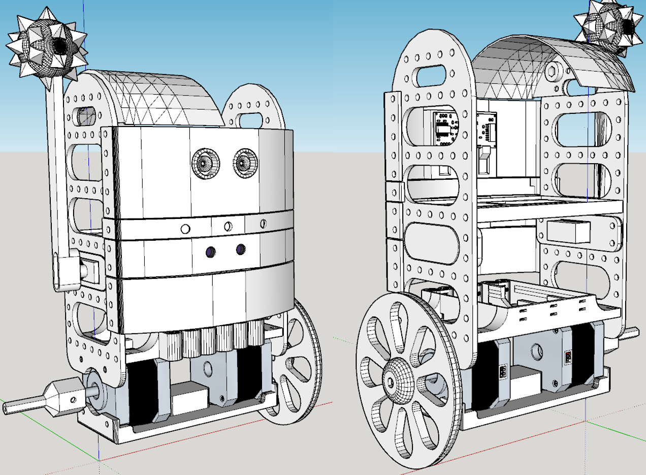
At the minimum, you will need to print :
- 2x body's sides
- 1x motors plate
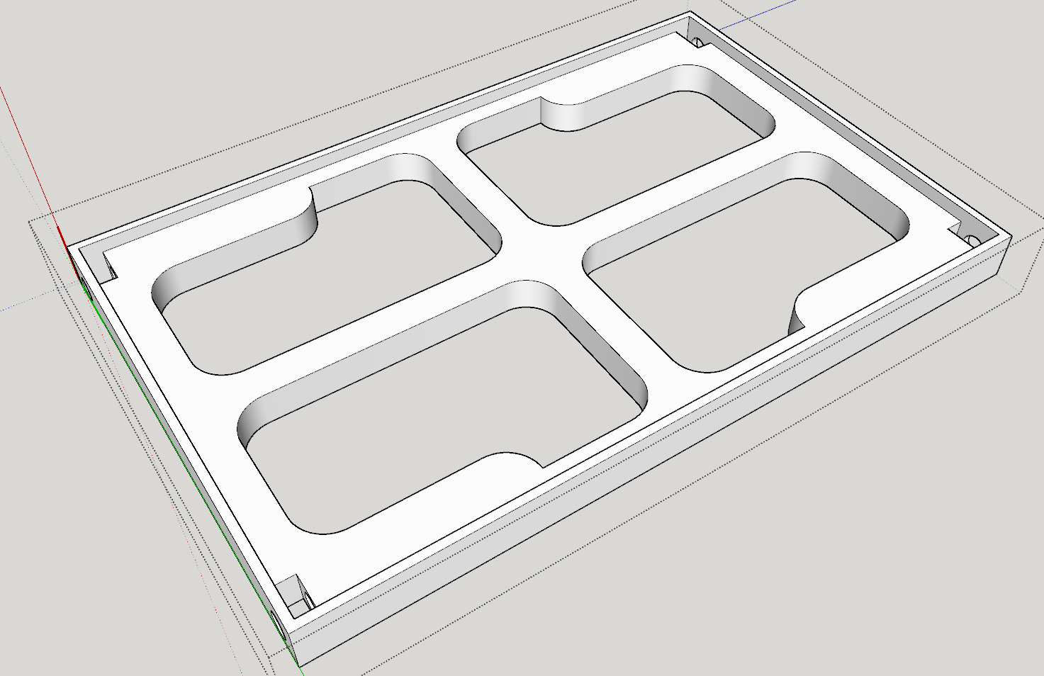
- 2x larger trays
- 2x wheels
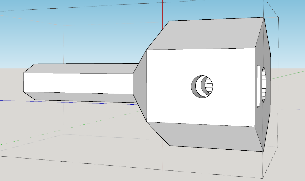
Other parts are optional (bumpers, SR-04 ultrasonic sensor holder, sharp gp2y0a02yk sensor holder, LED strip holder, arm...). If you intend to use salvaged RC car wheels like I did later, you will also need 2 shaft drive parts, or design you own if mine don't fit your wheels.
Everything is hold together using 3mm screws and nuts. I designed the robot to be easily assembled or disassembled using just a screwdriver : just put a nut in each tray's slots and it will act as a wrench.
If you plan to use the 3D printed wheels and the shaft holes are a little too large, you could add a little hot glue to the motor's shaft and it will hold the wheel very well. You will need 2 rubber bands for the tyres otherwise the robot will slip on the ground.
If you use my shaft drive parts, you have to put a 3mm nut in the rectangular slot, and a 3mm screw will block the shaft drive to the flat part of the motor's shaft.
Discussions
Become a Hackaday.io Member
Create an account to leave a comment. Already have an account? Log In.