Table of contents
1. Introduction
2. Description
3. Team
4. Goals
5. Design consideration
6. Requirements
7. Block Diagram
8. Hardware
9. Software
10. Firmware
11. Documentation
12. Prototypes
13. Market comparison
14. Media
15. Launching
16. Timeline
17. Tools
18. Testing
19. Production
20. Open Source Licence
21. BOM (Bill of materials)
1. Introduction
The rangefinder is a tool that allows you to determine the distance to obstacles and walls in order to avoid them. The rangefinder is perfect in robotic applications where the robot needs to move and go to a determined position in unknown territory. This sensor is great to determine the distance to the walls .The design was started in 2010 and continued on and off until present. It went over through three prototypes which tried to improve the design.
2. Description
The rangefinder has two sensors placed at 90 degrees that read the distances simultaneously.

Here are some of the unit details:
- detectable range: 200 mm to 1500 mm (7 to 60 inches )
- 7.5 degrees angular resolution
- 2 scans per second
- 180 degrees view
- easy readable output data in text format
- easy interface with other boards
- it comes pre-calibrated
- USB interface power and data
3. Team
We are a small team of engineers from Cleveland and we like to tinker with stuff and work on all kinds of interesting projects. In the past we participated twice at Centennial Regolith Challenge, a competition organized by NASA and California Space Authority. This is where we came with the idea of creating a cheap obstacle detection unit. Since we payed all the costs for the robot, transportation, and the competition fee, we did not have a lot of money to spend and we lacked proper sensors. The obstacle detection units that are on the market today start at more than a thousand dollars, which we could not afford. Also Kinect would be great if it would work reliably in daylight.
4. Goals
Our goal is to create a cheap 2D obstacle sensor that could be used in robotics.
5. Design consideration
a. Choosing plastic for enclosure
The enclosure has to provide some rigidity.
| Name | Rigidity | Machinability | Problems |
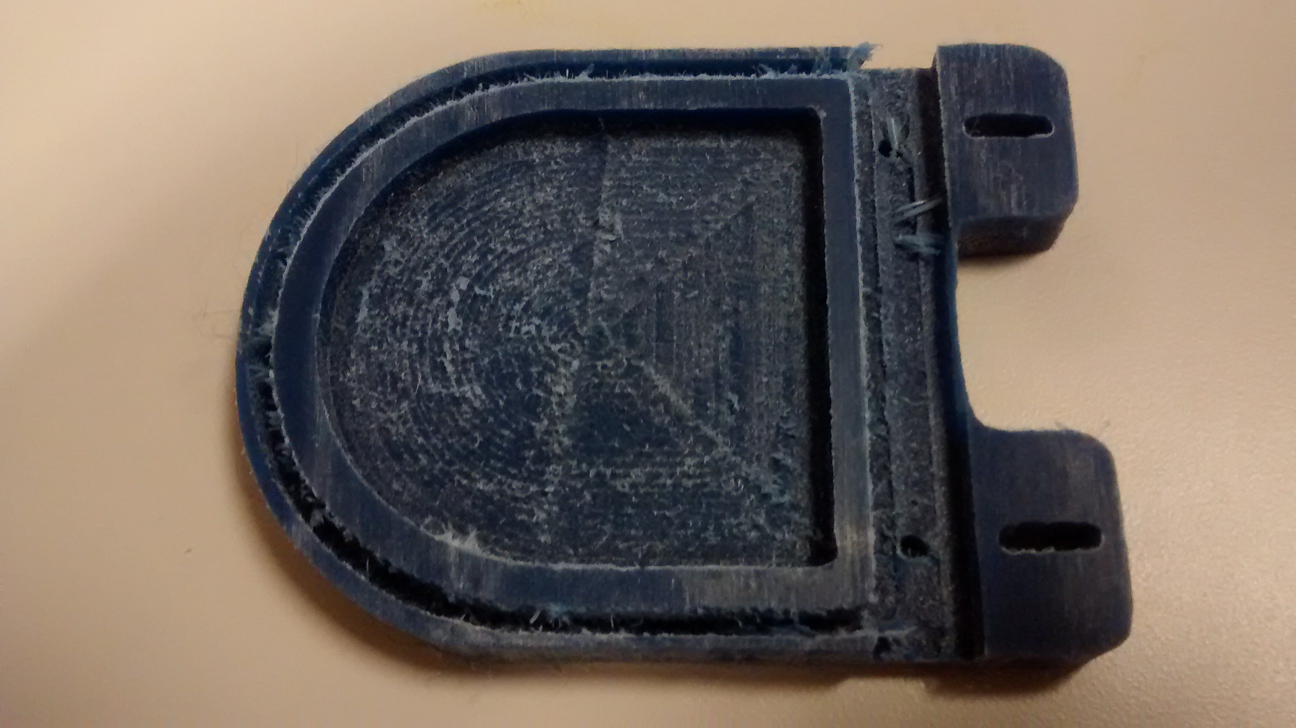
| Nylon | Medium | Medium | The finishing after machining is not so great |
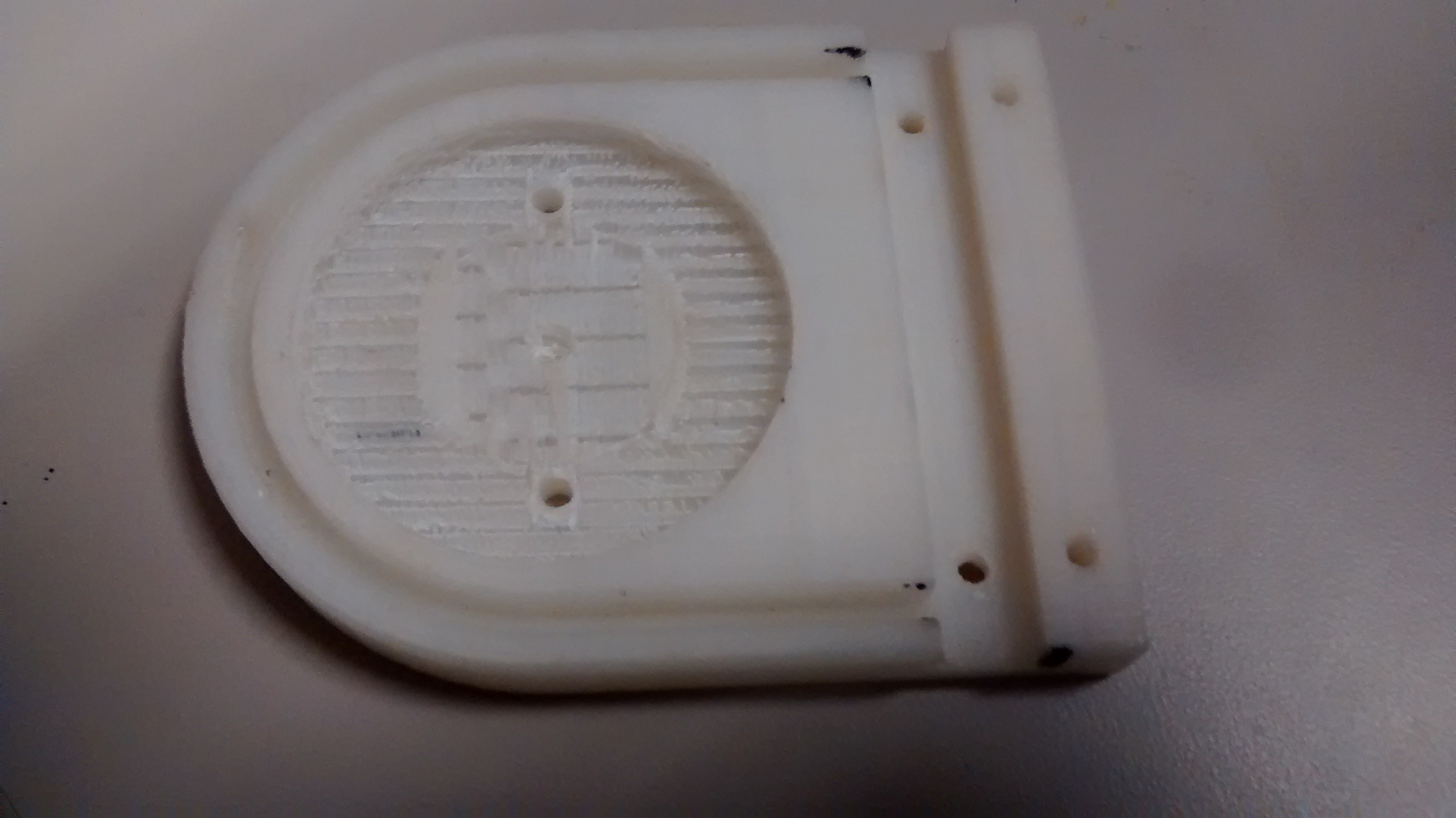
| 3D Printer Thermoplastic | Good | N/A | Finishing is not so great |
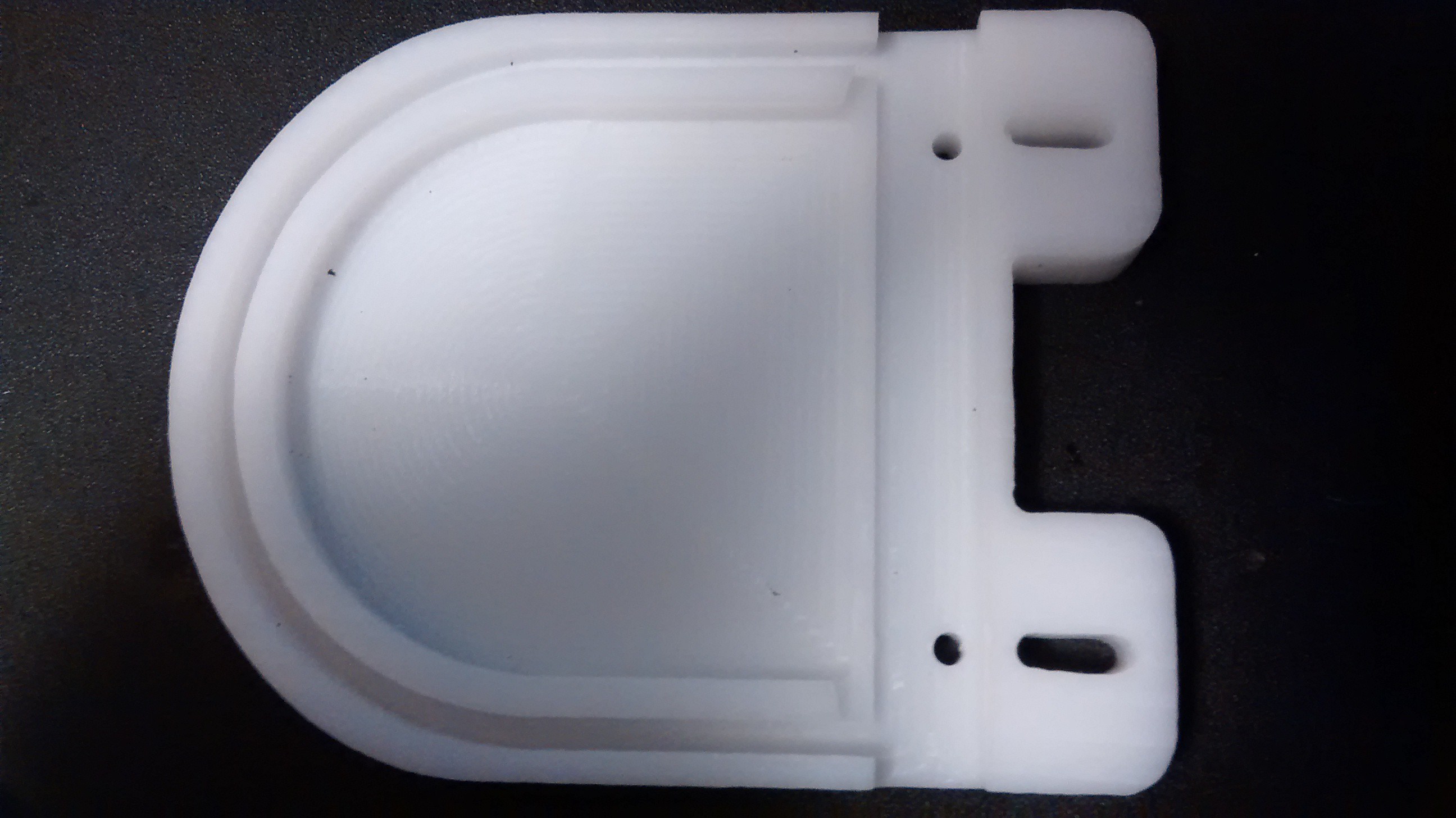
| Delrin | Good | Good | Finish acceptable |
Almost the whole enclosure is made from a single piece of plastic.
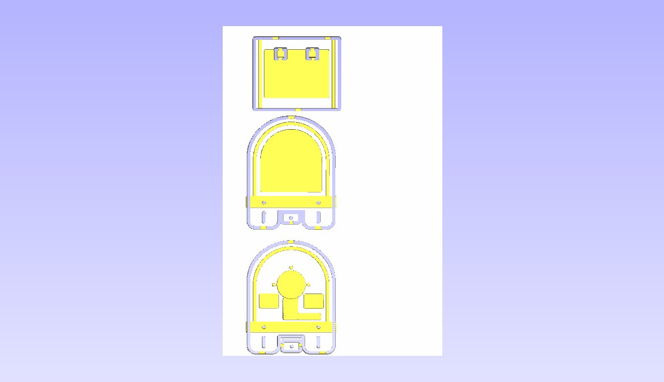
We choose 3/8 in Delrin which has very good rigidity.
Nylon CNC part
The 3D printed part
The Delrin part
The enclosure has to provide some rigidity in order to hold the screen.
b. Choosing the microcontroller
Some of our requirements for the microcontroller were 12 ADC resolution, UART interface, a good API, familiarity, and price. Those are the choices we had at the design time and the choices might be different today.
We decided to go with STM32100 which has an ARM Cortex core at 24MHZ. It provides some very good performances and low power for a low price.
c. Choosing the stepper motor
The goal was to choose a cheap stepper motor with enough steps /revolution to give enough readings. Also the supply voltage and the price came to consideration.
d. Choosing the sensor
The idea was to use a sensor that can be used outside and be affordable
The Sharp sensors are notoriously noisy. One way to mitigate this is to add a capacitor very close to the sensor between Vcc and ground.
Also the sensor can provide about 50 readings per second or about 40 ms per reading.
e. Power
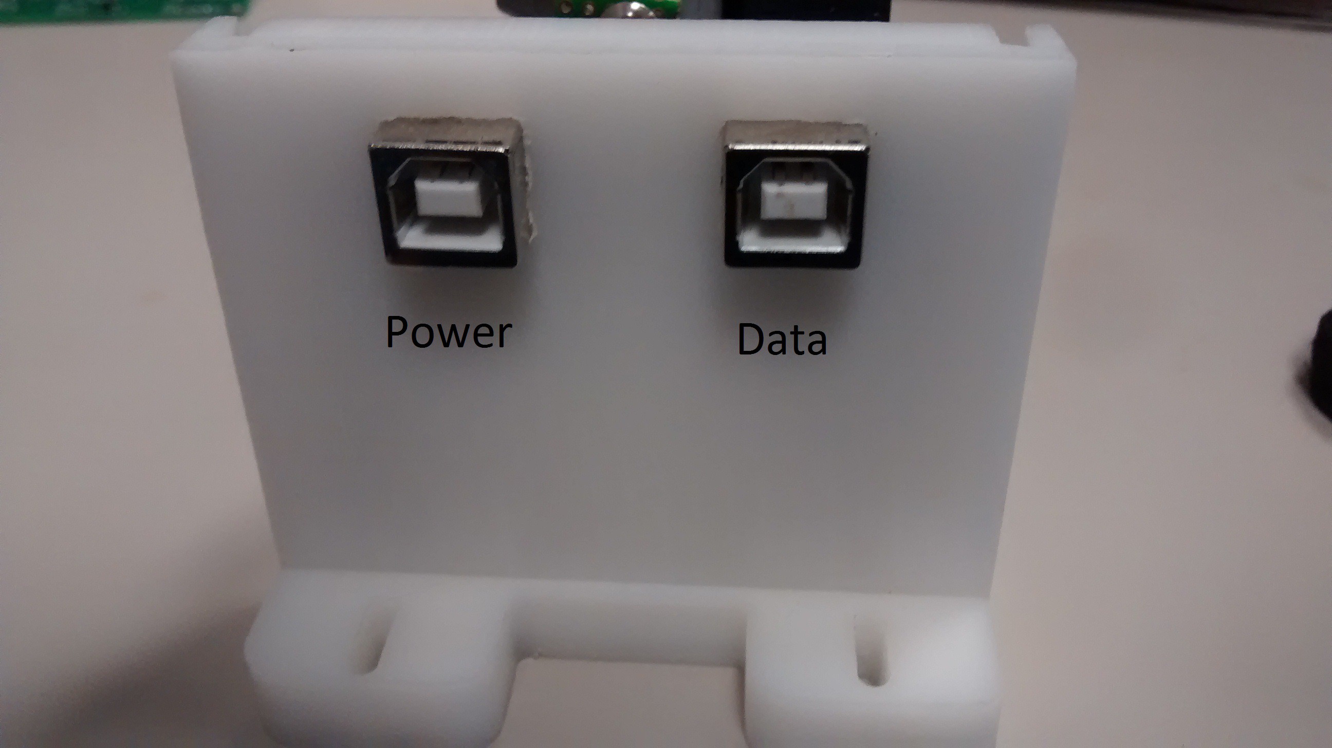
Since the unit will use more than 500 mA (which is the USB standard and also it cold be used with smaller boards such as Raspberry Pi, we decided to use 2 USB connectors . One is strictly for data and the other one is for Power.
6. Requirements
a. Easiness of manufacturing
We compared between a CNC Machine and a 3D printing machine for manufacturing the enclosure
| Name | Price | Materials | Problems |
| CNC Machine | $1600 | Wood, Plastic, Metal | Not very Complicated 3D forms |
| 3D Printer | $500 | Plastic | Warping |
b. Simple interface
The unit is seen as a Serial port by the host computer.
It can be queried directly from command line and the commands and data are text so is humanly readable.
c. Cheap
We continuously try to improve BOM (bill of materials) for the cheapest parts and labor.
d. Use simple manufacturing technology
e. Built with materials available locally
The plastics can be sourced locally from suppliers. The electronic parts are generic and can be found at more than 3 distributors.
f. Have a USB Interface and possibly a RS-232 (serial) interface
The unit provides a USb interface
g. Windows and Linux compatibility
We use FT232 USB chip that is very well supported by Linux and Widows , and it is seen as a serial port.
7. Block Diagram
8. Hardware
The PCB was designed in Eagle Cad and sent out to a PCB manufacturer.
Here are different versions of the PCB
The boards were populated inhouse.
9. Software
So far we have a C and a C# API and graphical interface. We plan to develop a Python interface.
In the picture there is the graphical interface that is written in C# and allows showing and capturing range data .
10 Firmware
The firmware is done in C for using the ST libraries. For development we used uVision and ST Discovery development board.
11. Documentation
a. User manual
The manual is available here :
b. Engineering manual
Here is the link to Engineering manual:
c. Software API Read.me
12. Prototypes
a. Prototype 1
The first prototype was done on breadboad. It had almost the same functionality as the later prototypes.
b. Prototype 2
This got the materials (Delrin) and the board is almost the same as the final version but bigger.
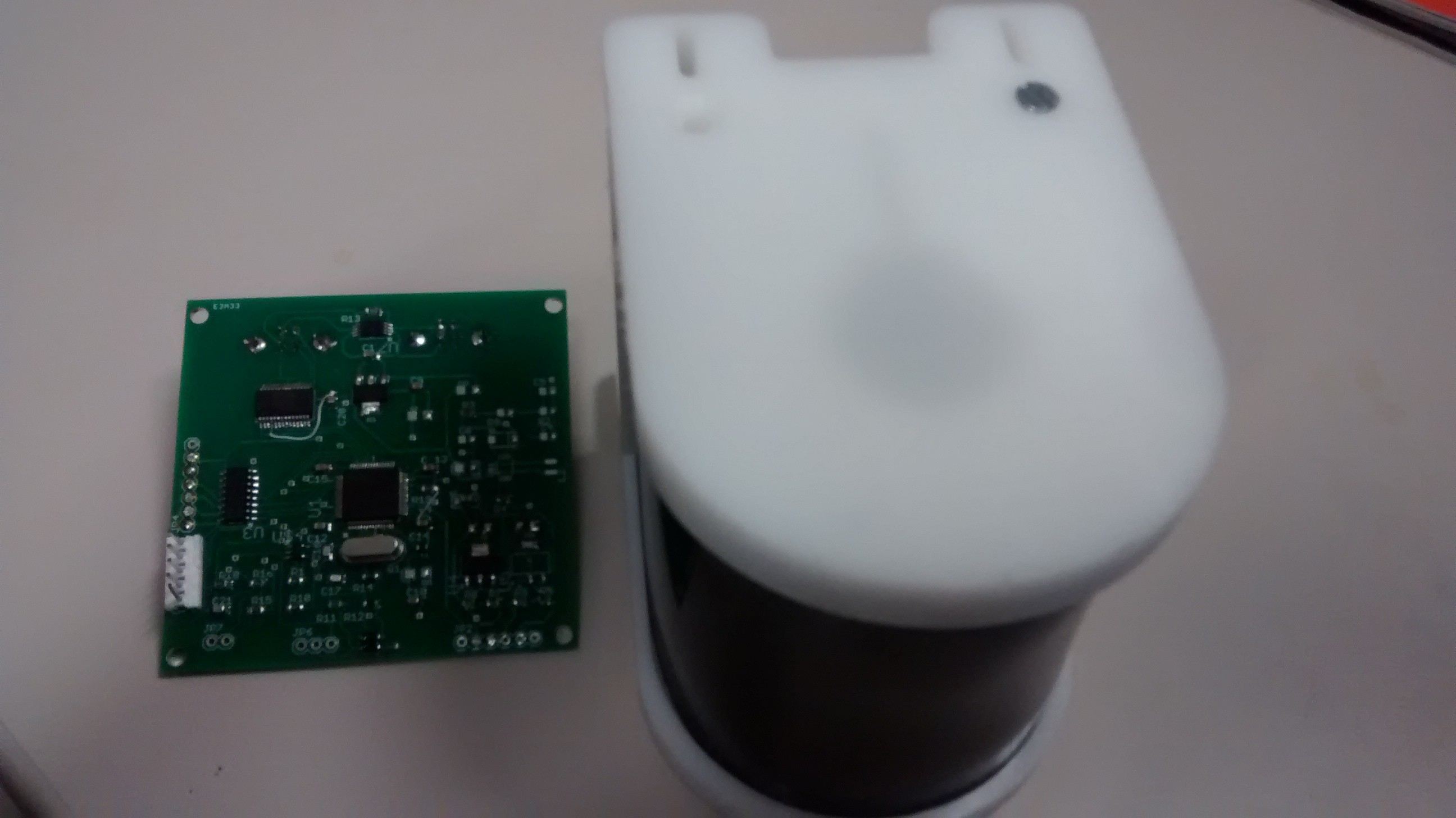
c. Prototype 3
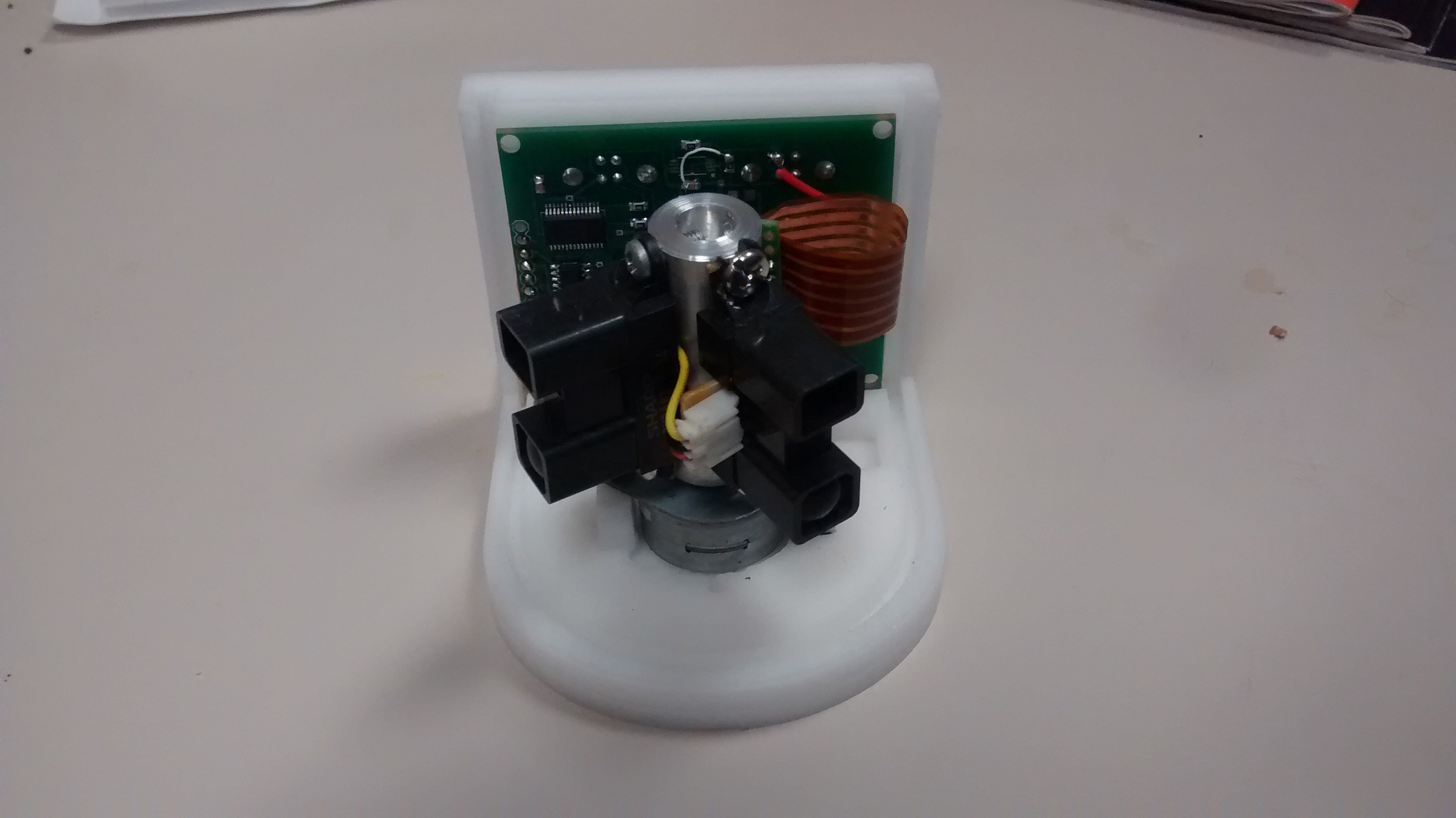
Comparison between Prototype 2 and 3. Prototype 3 is smaller and weights less
d. Final Product
Final product is very close to prototype 3 the board will have minor revisions. The flex cable will be smaller.
13. Market comparison
Here is a comparison between some obstacle detectors that are on the market
|
|
Robogaia 2D Robotic Obstacle Detector |
RPLIDAR 360° Laser Scanner | Hokuyo PBS-03JN Scanning Infrared LED Obstacle Detection Sensor |
| Range | 0.2-1.6 m | 0.2-6m | 0.2-3m |
| Usage Outside | YES | YES | YES |
| Interface | USB,possible serial | USB | RS232 (serial) |
| Price | $199 | $398.99 | $1135 |
| Scan Rate | 2HZ | 5.5HZ | 10HZ |
15. Launching
This is a pre-launching campaign designed to get emails before the Kickstarter campaign starts.
Also an email list was prepared for when the Kickstarter project will go online.
Prefundia http://prefundia.com/projects/view/robogaia-ir-rangefinder/802/
The Kickstarter campaign is not yet, but here is the preview link:
https://www.kickstarter.com/projects/1154457775/1027739962?token=a0ce096e
16. Timeline
| 2011 | 2012 | 2013 | 2014 March | 2014 April | 2014 July | 2014 August | 2014 September |
| Designing and prototyping enclosures | Got the CNC Machine | FirstPCB Prototype, Almost final Enclosure | Second PCB prototype | Third PCB Prototype | Showed the Project at Maker Faire Detroit | HackaDay prize submission | Go to Maker Faire New Yortk |
17. Tools
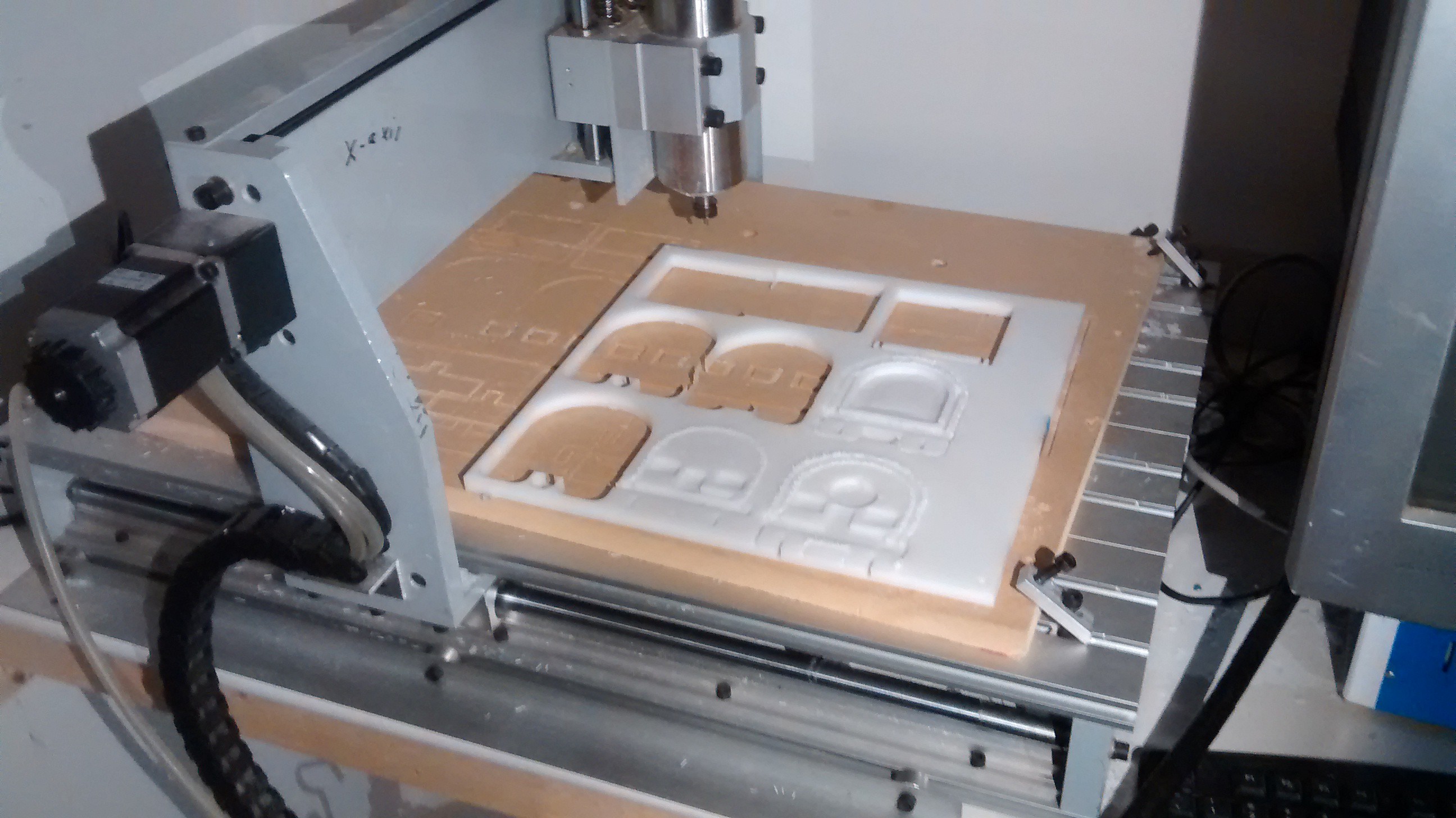
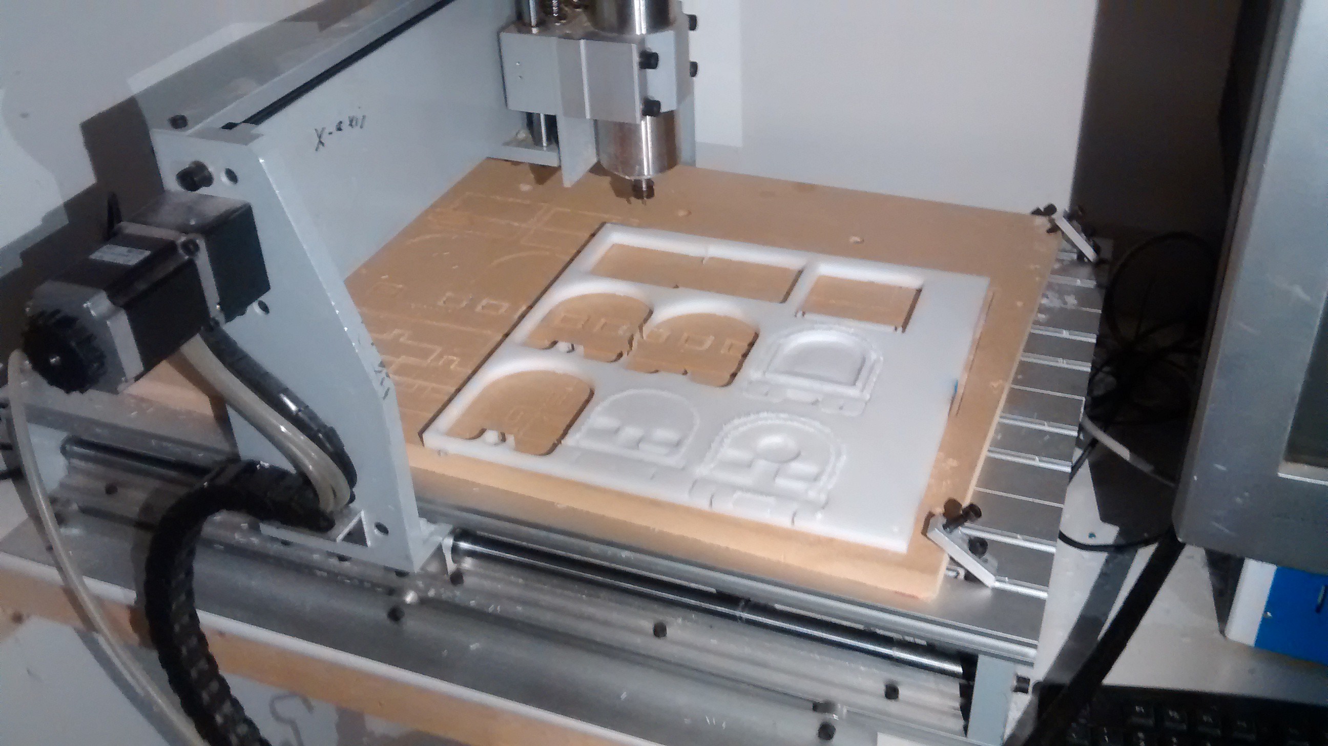
We used mainly a cheap CNC machine to build the enclosure. The CNC is driven by an old IBM computer with LinuxCNC installed. This proved to be enough for decent results.
18. Testing
a. Software/Firmware testing
b. Hardware testing
c. Pre EMI testing
d. EMI Testing
e. Production test rig
19. Production
Production will be done inhouse. The enclosure will be milled on the CNC machine.
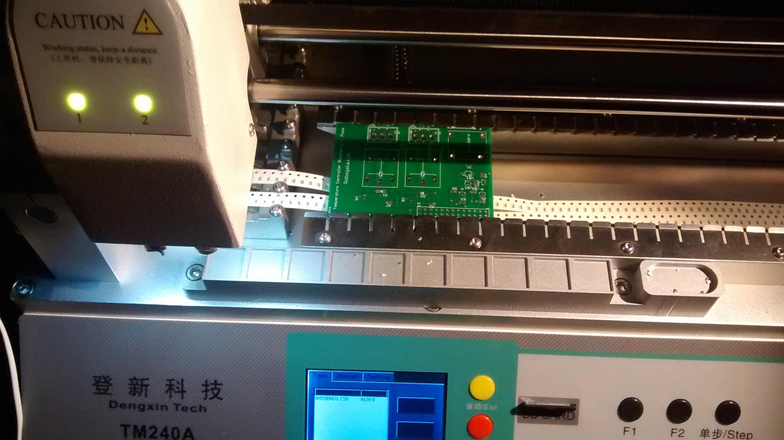
The bare PCB boards will be ordered outside and populated inhouse on the pick and place machine.
20. Open Source License
We will release all the software and firmware code and PCB design under Apache License 2.0 . We chose this license because it is very permissive and allows derivative work. We will include the license information on our documents related to the project.
here is the link to the license file :
http://www.apache.org/licenses/LICENSE-2.0.txt
21. BOM (Bill of materials)
A more complete list is available here :
 harry.olar