 Sam Pullman
Introduction
In this log, we will detail how we built and tested our initial functional prototype.
Processes
Our first step was to find rubber samples and set up a test enclosure. We acquired two types of rubber (neoprene and natural latex) in a variety of thicknesses (1/16in to 1/4in) and hardnesses form CAL NEVA Supply Co. Rubber hardness is measured by the Shore Durometer scale. We got rubber samples ranging from 20A to 50A (about rubber band to pencil eraser hardness).
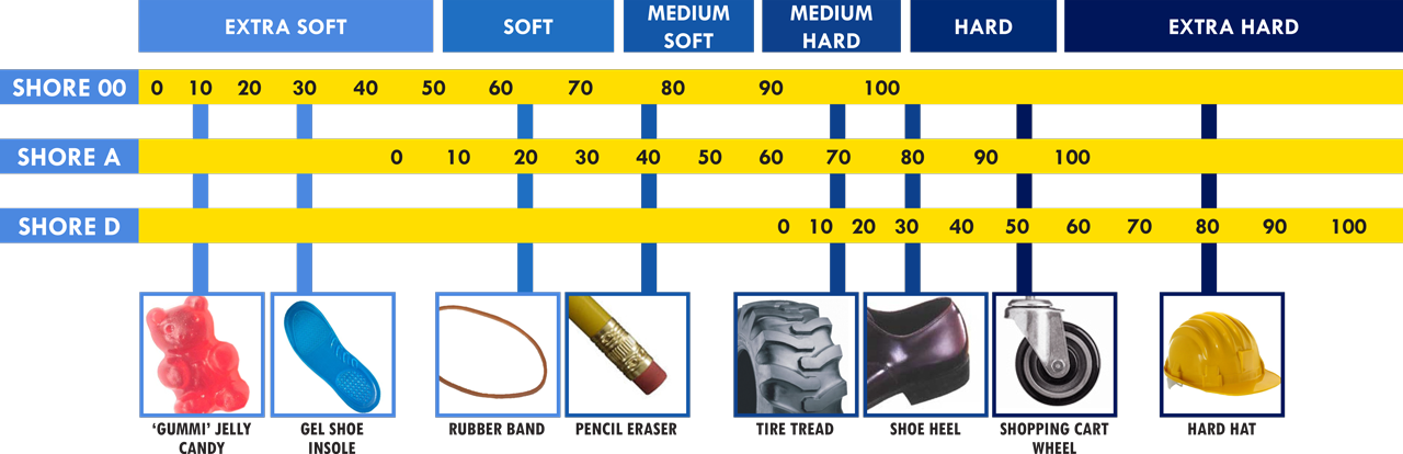
Image Source: https://albrightsilicone.com/a-guide-to-shore-durometers/
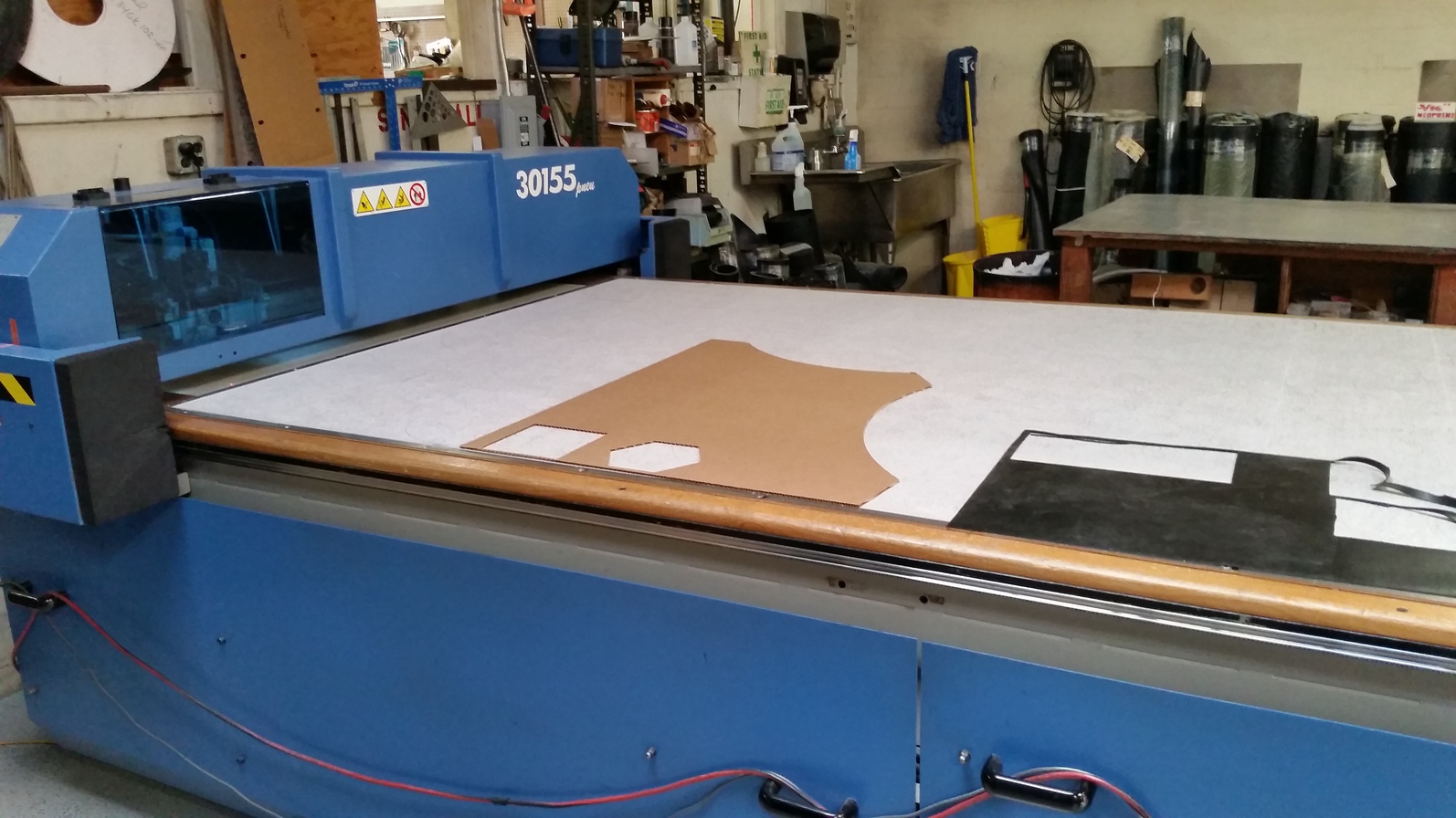
We found a local shop that specializes in cutting rubber into gaskets. They were kind enough cut out some sample radiators with their awesome CNC reciprocating knife. They said we were their first customer to ever use rubber to make sound rather than dampen it.
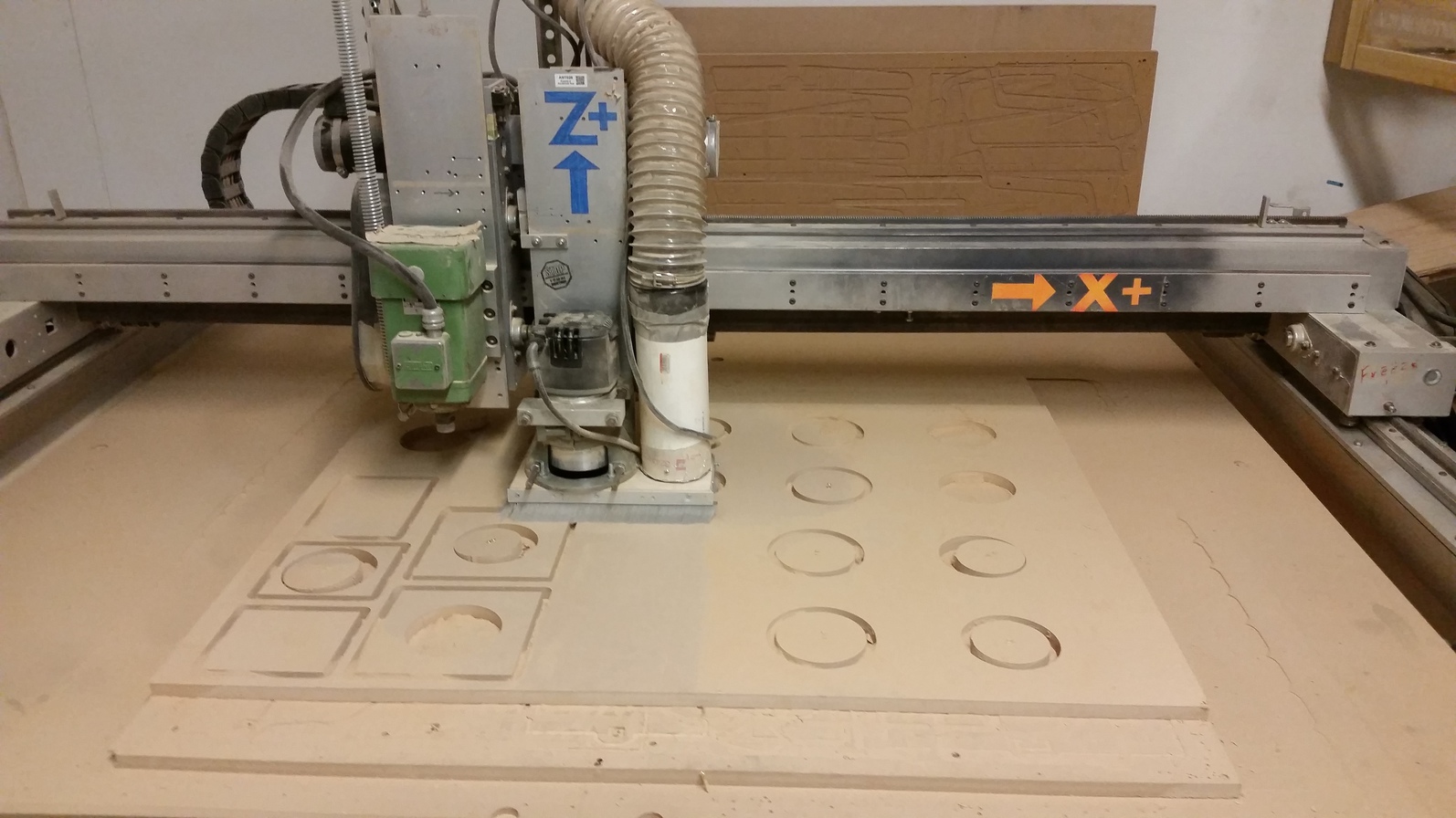
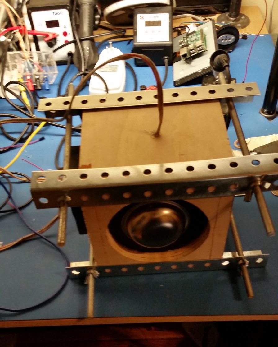
At the local hackerspace Ace Monster Toys I cut out a test enclosure with the CNC router. I designed the enclosure to make it easy to switch out different passive radiators.
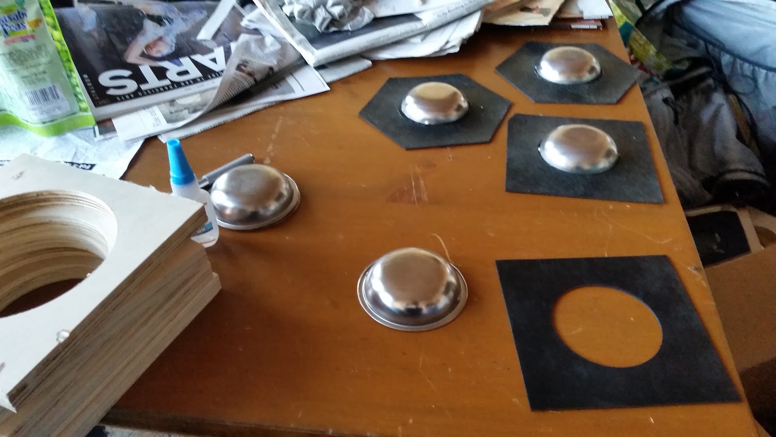
I also super glued up a few test radiators using some of the rubber samples and metal dishes. The metal dish is actually a ladle holder from Daiso. We ended up clearing out three different Daisos for their ladle holders!
Experiments
The goal of our experimentation is to characterize the DIY passive radiators made from various types of rubber. Then, we will input this data into speaker design software (WINISD Pro or BassBox6) to see if they can be tuned to extend the bass response of our enclosure. Finally, we must verify the computer simulations.
Equipment used:
- Scale – measuring mass
- Ruler – measuring diameter
- Graduated Cylinder – together with scale to measure density of rubber
- HP 3562A Dynamic Signal Analyzer – used for impedance plot (though a frequency generator and a multimeter would work just as well for determining impedance maximums and minimums!)
- BassBoxPro6 - http://www.ht-audio.com/pages/BassBoxPro.html
- Winisd Pro Beta - http://www.linearteam.dk/?pageid=winisdpro
To fully model a passive radiator the following parameters must be determined:
- Cms – mechanical springiness of the rubber
- Mms – moving mass of the radiator
- Rms – mechanical resistance of rubber
- Sd – diameter of the radiators
Notice that the first two terms are the same terms needed to determine the resonant frequency of a damped harmonic oscillator. We will use this fact to characterize the passive radiator.
Procedure:
- Plot impedance curve
- Measure resonant frequency
- Add known weight
- Plot impedance curve
- Calculate Cms from change in resonant frequency
- Use Cms Mms and Sd to model driver
- Guess and check Rms (by comparing to impedance curve)
- Use software to tune subwoofer for bass extension
- Verify software tuning
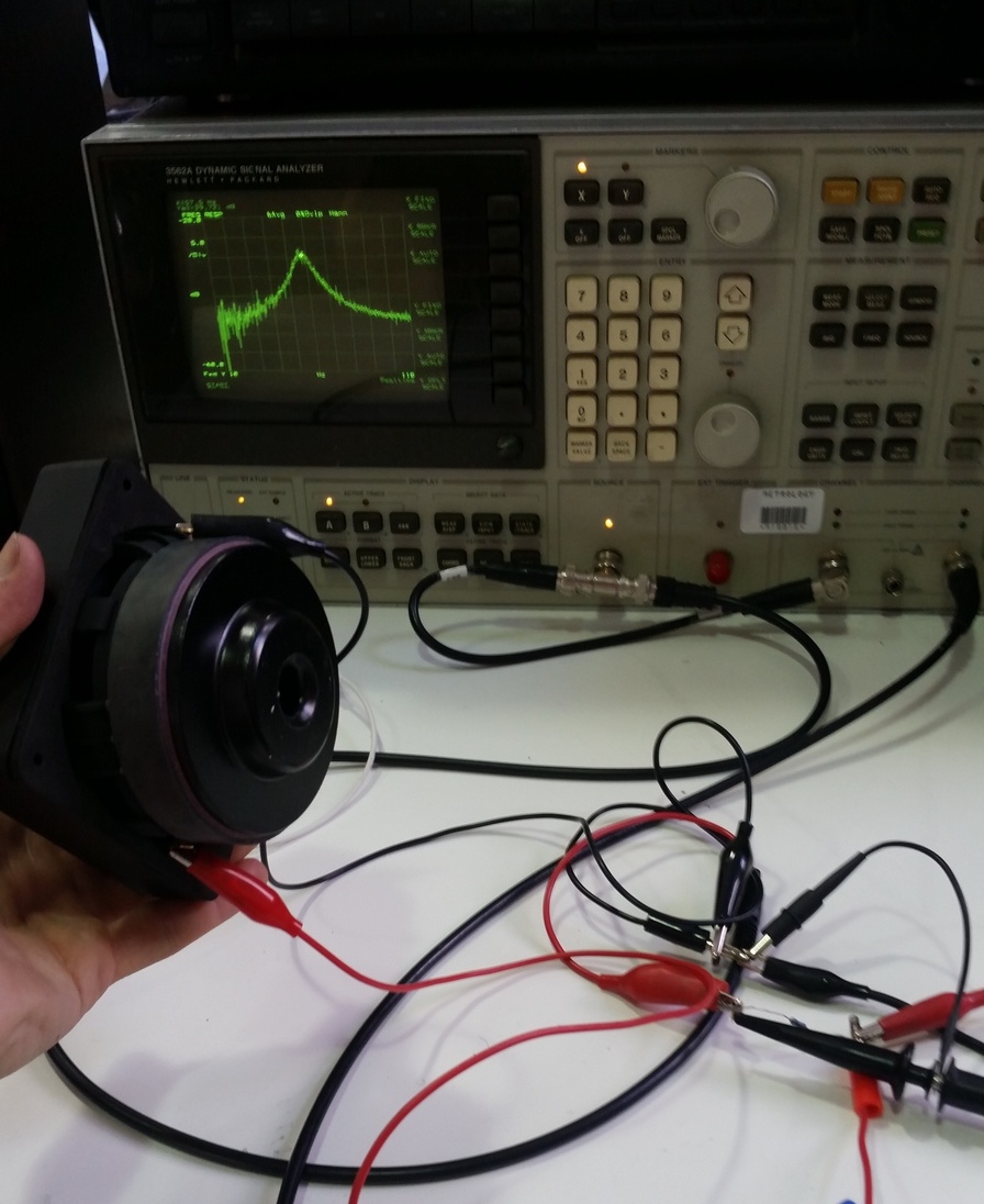
The above image shows the test setup for measuring the free air resonance of our driver. The HP 3562A dynamic signal analyzer sweeps frequency across the the driver and a 1K series a resistor. Simultaneously, it measures the voltage across the resistor and the driver to derive the impedance. For more details, see this PDF https://www.bksv.com/media/doc/bo0202.pdf
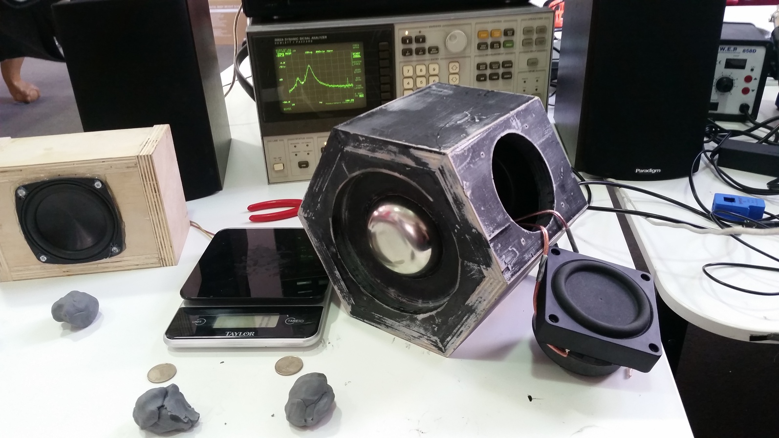
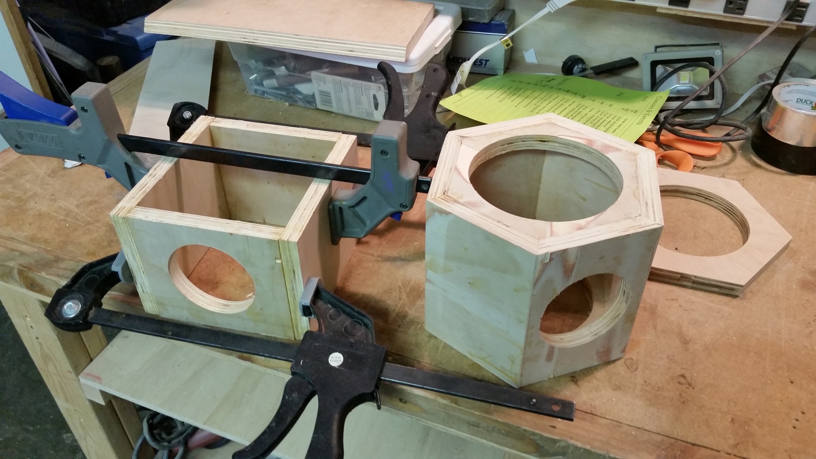
Above is our hexagonal test enclosure next to a scale and modeling clay. The modeling clay can be added onto the passive radiators inside the enclosure to tune their resonant frequency.
The next log will discuss the connectivity side of things. After that, we will log the speaker experimentation process in further detail, as well as describe the results of our analysis.
Discussions
Become a Hackaday.io Member
Create an account to leave a comment. Already have an account? Log In.