 I'm going to kick off this project documentation by showing you some, hopefully, interesting details about the mechanical parts, the 3D printing work and putting it together.
As I said: from bits to box!
My preferred place for print work is Shapeways, they generally do very nice work.
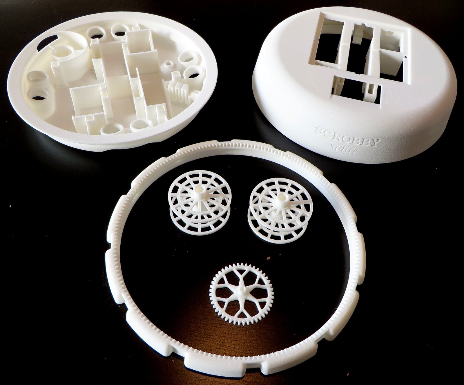
The first prototype of the Scrobby Solar consisted of only five 3D printed parts, as shown on the right. Top left is the bottom half of the shell, with the top half next to it. The larger centre part is the main brush. This is what will do the cleaning, plus it'll be what the robot rests on... Look mommy, no wheels!
The part is actually a miniature slewing ring, including a gear and bearing race.
Shown inside the slewing ring are the two spools for the tether wires and a gear to drive the slewing ring.
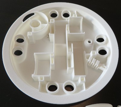
The bottom shell in some greater detail shows how I used square shapes for the non essential surfaces, in order to save polygons for the round faces (the 1M poly limit at Shapeways). In the bottom right is a small zigzag bit, this is a sprung opening to the raceway to allow inserting the bearing balls. Afterwards a 2mm pin can be inserted to hold it into place.
It turned out the fitment was quite spot on for most part. The holes for the ultrasonic sensor were modelled 0,15mm oversized and turned out to give a nice snug fit. The motors were a tight fit though, so after breaking out the callipers it was found the model had been printed to scale on two of the three axis, but a bit undersized on the 3rd (about 0,3mm per 100mm). No worries though, the device still fit together nicely.
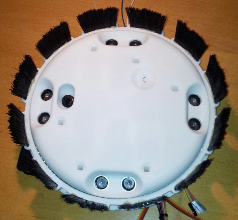
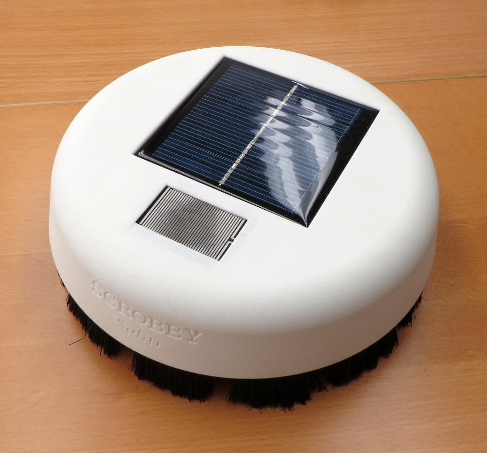
And this is what it looks like from the bottom, after painstakingly glueing all those little hairs in (took me a day the first time, pfew)...

Discussions
Become a Hackaday.io Member
Create an account to leave a comment. Already have an account? Log In.