 WJCarpenter
{Editor's note: I re-read all of the project logs to refresh my memory of some things. I was surprised to find out I had started the project log almost exactly 3 years ago. That's slow, even for me, and I was already thinking about it for a while before I got around to making this hackaday.io project. Sheesh.]
I've got most of the logic of the circuitry laid out on a breadboard now. Since this is just proof-of-concept for the esphome.io stuff, I only bothered with a single PIR sensor and a single rotary encoder. For the dimmer feature, I am driving an LED through one of the N-channel MOSFETs that I plan to use. The display is just showing some simple status information as I test things out. I haven't yet designed what the display will look like when the system is operational.
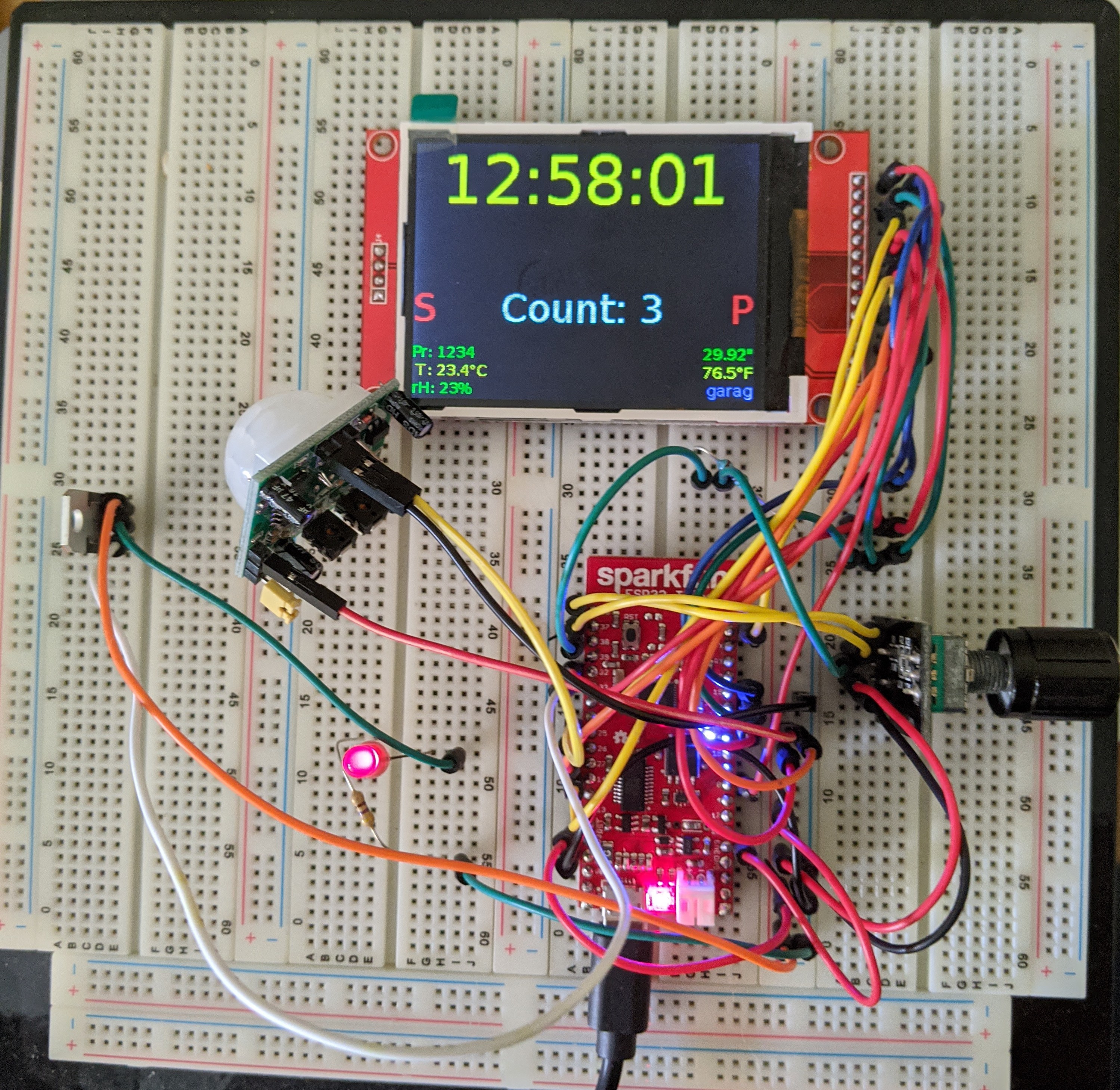
- The "S" changes from red to green while the rotary encoder switch is pressed.
- The "P" changes from red to green while the PIR data line is high.
- The "Count" value is keeping track of rotary encoder ticks.
- The clock value is kept in sync OTA by a esphome.io component. (Who doesn't need another clock?)
- The smaller text is just dummy stuff so I could get an idea of the font rendering.
Discussions
Become a Hackaday.io Member
Create an account to leave a comment. Already have an account? Log In.