WJCarpenter
-
Pull up! Pull up! Pull up!
07/22/2020 at 03:30 • 0 commentsI've had this project on the back-burner for a while, but I've recently started dusting it off.
First, I have to say that I'm pleased with the amount of effort I put into labelling pins on the schematic. It's a fact of life in microprocessor board land that every pin tends to have 3 designations. There is the name the chip maker gives the pin on the chip. There's the name the breakout board maker prints on the silkscreen. And then there's the constant defined in some board definition that fits into a programming framework. Those multiple names bedevil us all. However, I put just about everything that I could identify onto the schematic, so it minimizes the amount of remembering that I have to do now after all this time. Yay, me!
Second, I'm slightly annoyed at something, and I can't find anyone to blame but me. When I got to laying a few things out on the breadboard again, this time with connections matching the schematic design, I discovered something about the ESP32 that I guess a lot of people know. GPIOs 34-39 are input-only pins. I knew that and took it into account in my schematic and board layout. The part that I didn't notice is that those pins also don't have any internal pull-up/pull-down resistors. In my design, I'm using pins 35 and 38 as the inputs pins for the switches built into the rotary encoders. Not only do they float, they wander aimlessly up and down on the breadboard. Grrr. Looking at the board layout, it looks like I won't have too much trouble soldering on external pull-down resistors. It's just annoying.
It would be less annoying if I hadn't already had the boards made long ago. If I end up having to re-do the boards for some other reason, I can fix the design to change a couple of pins. With the current design, I've still got a few no-connects, and I was thinking of adding a bit-banged I2C bus (I might as well have a temperature sensor in my garage).
-
FreeRTOS calls
11/05/2017 at 22:03 • 0 commentsI guess I'm going to seem pretty fickle about the software environment, but it's really born of ignorance rather than wishy-washy-ness.
Earlier, I commented that I would probably use Lua so that I could take advantage of multi-threading to simplify the logic of the control software. I knew that the ESP32 has FreeRTOS inside. After all, that's what at least one of the Lua implementations is built on. What I didn't realize until today was that the ESP32 plugins for the Arduino ecosystem exposes most of the FreeRTOS calls. (It was brought to my attention by this youtube video #168 ESP32 Dual Core on Arduino IDE including Data Passing and Task Synchronization from Andreas Spiess.
Once the idea got into my thick skull, I found there was plenty of tutorial and reference material for making FreeRTOS calls from within an Arduino sketch. The main advantage, of course, is the availability of plenty of Arduino-targeted libraries for devices and sensors. Perhaps the same is true for Espressif's SDK for the ESP32. I'm going to start with the Arduino ecosystem in the interest of getting this project done in less than 12 parsecs.
(Notice above I said Arduino ecosystem instead of Arduino IDE. Since I have been a software developer for a long time, the Arduino IDE drives me a little crazy, though I understand why it is the way it is. Anyhow, I hope to some day spend the time to iron out a smooth path to doing in some other tool what is convenient in Arduino IDE.)
-
A different box for the controls
10/26/2017 at 03:42 • 0 commentsI said earlier that I planned to use a double-gang electrical box to hold the smarts. That was because things just won't fit in a single-gang box. For a different project, I went sight-seeing in the hardware store for enclosures. I found something that I had overlooked before.
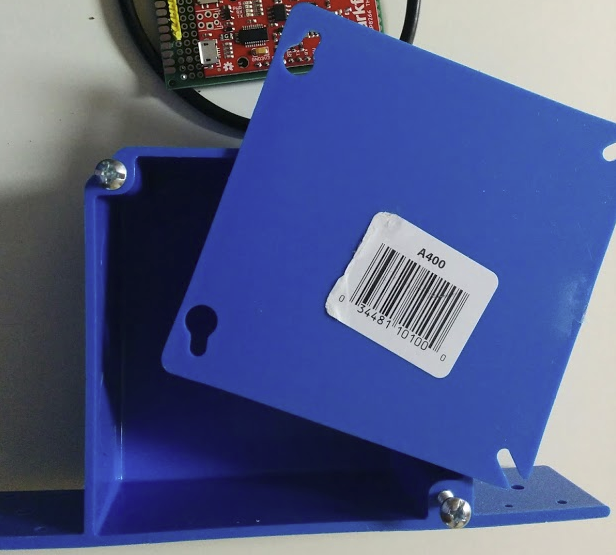
Here it is:
![]()
Those mounting tabs on the bottom corners are easily trimmed off. The cover is not a double-gang outlet cover because this box is intended to be used for junction points for wiring. The cover for it is mostly a big, flat, blue square. This should give me the option of mounting the screen horizontally or vertically (or, if I'm really wacky, diagonally).
As I mentioned, I used this for a different project, and the result was satisfactory for something that will live in an out-of-the-way place.
-
Knob, knob ... who's there?
10/26/2017 at 03:30 • 0 commentsGood news today on the physical aesthetics front.
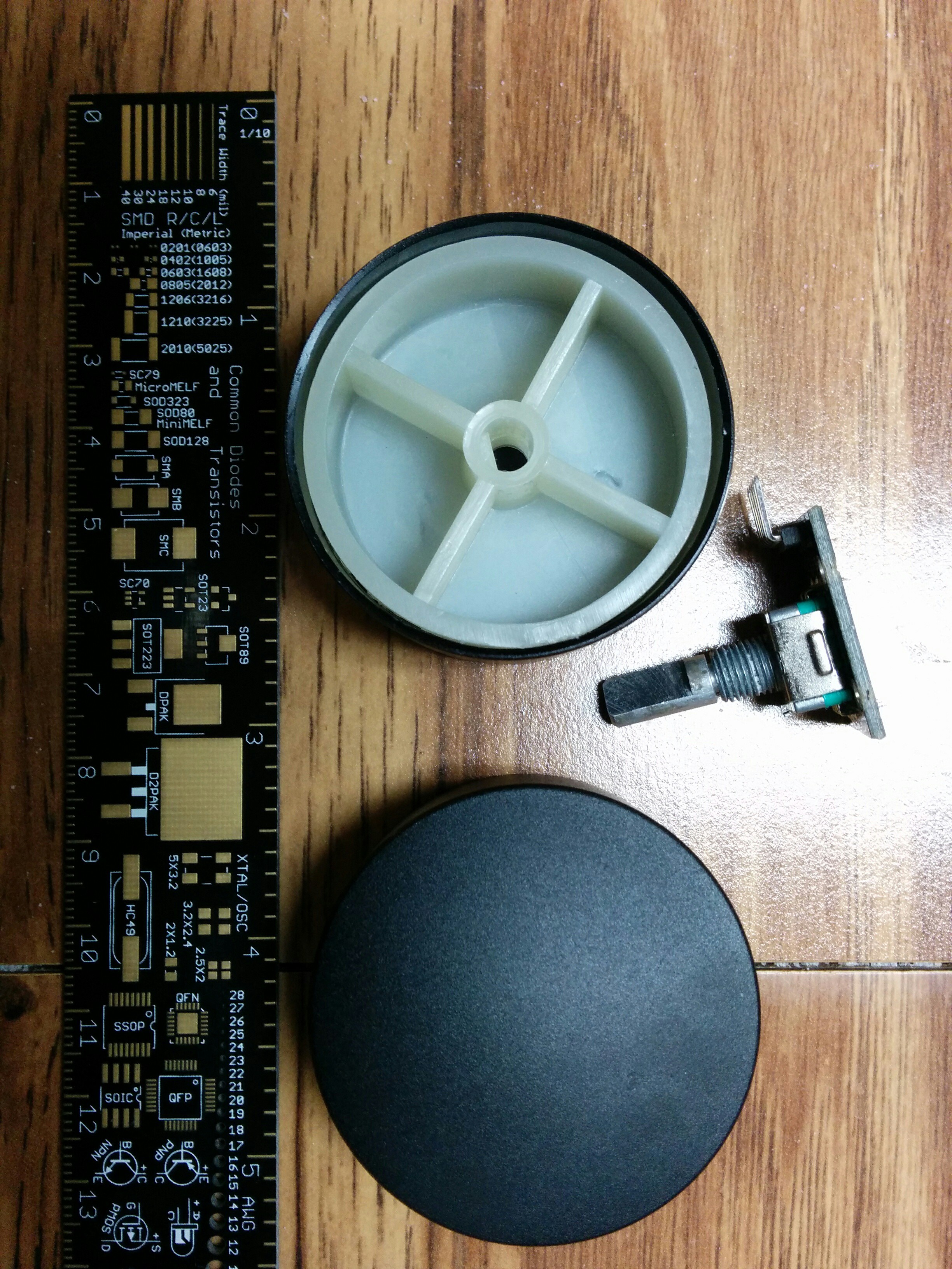
Most of the inexpensive rotary encoders you find in the usual places have a "D" shaft, meaning that the part of the shaft where you put the knob is shaped like a "D". It's also really easy to find the small half-inch-diameter-or-so knobs for those "D" shafts. But I don't want those tiny knobs that someone might have to fiddle with in the dark. I want nice big knobs that are 1.5 - 2 inches in diameter.
Well, those big knobs for "D" shafts are pretty hard to find. It's possible to find a few, but many do not have the right size "D" cavity, so they don't fit. That was the case with the nice looking knobs I mentioned in an earlier log item. My good news is that I finally found some that are really, really nice. In relative terms, I paid way more for a pair of them than I wanted to, but in absolute terms it was just over $10 for a pair of them; and it's a one-time purchase. They arrived today and fit snugly over the "D" shafts of my rotary encoders.
Yay! Here they are. They have a nice matte finish and should be pretty easy to manipulate when I mount them. Even with arms loaded with groceries, it should be able to activate the on/off switch with the push of an elbow.
![]()
-
Tickled green
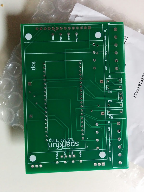
09/28/2017 at 02:01 • 0 commentsI received my PCBs today, and they are beautiful. I used the Seeed Fusion service. (The boards are very inexpensive, but the shipping from China to the US is pretty steep.) "Back in the day" , I've made some of my own PCBs with some of the usual home-based methods. Although they worked (sometimes), they always looked like a mud pie. This is the first time I've used a fab to make custom boards. They are gorgeous and exceed my expectations.
![]()
That's right. I did label the "top" and "bottom" of my board. Hey, they're both green, white, and silver.
-
Updates on various things
09/25/2017 at 23:52 • 0 commentsIt's a good thing I don't do this for a living, because I don't go very fast. Mostly it's because I act like a dog that goes in a different direction every time it smells something new. I've worked through several things without updating the project log. Here are quickies for those:
- I'm now using the SparkFun ESP32 Thing. I chose that mainly because it's got enough available pins, and I had one right here in the parts department.
- Now that I have moved to an ESP32 board, I found a very nice Lua implementation from this European education (not sure) project: whitecatboard.org. The thing I like about it, compared to the NodeMCU flavor of Lua, is that it has true threads via Lua-RTOS-ESP32 instead of just co-routines. I think the threads are going to simplify my software quite a bit.
- For a while, I was planning to use this D-duino-32 V2. It has a small SSD1306 OLED screen right on the board. I don't really need a display for this project, but I thought it might come in handy for the software development phase when it wasn't convenient to have the serial console running. Although the display is rather common, and there is good support for it in the Arduino/C/C++ community, there isn't currently support for it in Lua-RTOS-ESP32. I considered porting a graphics library into the Lua-RTOS-ESP32 ecosystem, but it seemed like more work than I felt like doing.
- While looking into the display possibilities from the previous bullet, I decided to have a look at the displays that Lua-RTOS-ESP32 does support. I was completely shocked to find out that these days you can get a 2.8 inch 240x320 TFT display (with touch interface! with an SD card slot!) for under $10 from multiple vendors if you can wait for shipping from Asia. What? And, you can get it faster in the US for only a couple dollars more. Like I said, I don't need a display for this project, but that doesn't mean I can't jam one in there with some contrived rationalization.
- Putting the display into the project definitely rules out using a single-gang electrical box for the main control unit. The display module itself will not fit. I've decided to move up to a double-gang box and will mount the display horizontally. I thought it would be pretty easy to find a clear plastic blank faceplate, but it turns out to be difficult. In fact, I never found one. I settled for one with cutouts for two ordinary toggle light switches. It's the kind of faceplate where you can put in your own wallpaper so the plate matches your walls. I may later decide to use a normal opaque blank faceplate and cut a rectangular hole just right for the display (though I'm sure I'm doing a better job in my mind than I will in practice).
- I finished the schematic and the PCB layout. Even with a double-gang enclosure, it was still tricky to fit everything on the board. I made a sort of layer cake out of it. The voltage regulator module is going on the bottom side of the board (which will be handy anyhow if there is any modest heat buildup). The ESP32 module is on the top of the board. Because I plan to mount the TFT display using tall-ish female stacking pins, the display sits on top of the ESP32 board with plenty of clearance. The other small parts are scattered around both sides of the board where they fit well or where I thought they would be most convenient. There are tons of screw terminals for connecting wires from the remote boxes.
- I sent the board Gerbers off to Seeed Fusion and am now waiting.
- I have not started the software yet, though I've been doing some mental planning.
-
yo, circuit.io, no!
08/20/2017 at 03:20 • 0 commentsThat didn't take long. I spent a couple of hours on circuit.io, which looks like it is not Autodesk Circuits. It was sort of OK, sort of meh. But when I got to creating a schematic symbol from scratch ... that was a dealbreaker:
They give you a handful of drawing tools, but the tools have no idea they are drawing schematic symbols (except for the "pin" menu item). Once you put something onto the editor page, you're not going to change it much. You can select it, and then you see a small context-sensitive form along the bottom. Would you like to move a part? No problem, just select it and then fill in the appropriate X/Y coordinates. If you want to move several parts, do each of them individually. The part I need to make has 26 pins, but it's not a DIP.
There certainly might be an friendlier way to do that, but I didn't discover it. (Large swaths of the site look like they haven't been touched since 2015, so I'm not optimistic about improvements.)
Anyhow, I'm back on upverter.com. I still don't remember why I left.
-
online design sites
08/19/2017 at 21:29 • 0 commentsDespite the fact that I was once a software guy working on a tiny piece of a gigantic in-house EDA suite, I've never really spent any time designing something in a real EDA environment. So, prompted by Brian Benchoff's series http://hackaday.com/2016/09/21/creating-a-pcb-in-everything-introduction/, I set out on a quest to do that. My plan was to limit myself to the online EDA tools for now.
I started at https://upverter.com and got about half-way through the schematic. I became unhappy with it for reasons that I now honestly cannot remember. I think I was having trouble finding things in the parts library or something.
Anyhow, I started over at https://easyeda.com. Maybe if I were a practicing EE things would be a lot more clear, but I found it fairly difficult to grasp all the "easy" things they were trying to tell me. It doesn't help that there are many busted help links. It was painful, but I stuck with it and actually got all the way done with the schematic. That included making a schematic symbotl for a D-duino-32 V2 (https://www.tindie.com/products/lspoplove/d-duino-32-v2arduino-and-node32-and-esp32-and-096oled/, more about that in a separate log post).
Now comes the time to push a button and get a PCB layout. A couple of my schematic parts don't have footprints. That's when it became pretty frustrating. There is an editor for making PCB footprints, and I know the exact size of the D-Duino-32. It's mostly a rectangle with rounded corners. I wasted a lot of time trying to just get the rectangle part with the correct dimensions. I don't mean the correct dimensions plus-or-minus a few tenths of a millimeter. It would have been awesome to have a property sheet so I could just type the numbers, but I had to (try to) do it tediously with a drawing tool. Maybe there is a way to do this that is a whole lot easier, but I refer you to my previous comment about busted help links.
I plan to check out one more site (https://circuits.io/). If that doesn't fill me with bliss, I'll probably go back to upverter.com.
-
pin money
08/06/2017 at 21:42 • 0 commentsWell, I've done it again. With all the bells and whistles, I don't have enough GPIO pins on the NodeMCU. Here's what I need right now:
4 outputs with PWM
8 inputs with interrupts
2 outputs with simple on/off
That's 14 pins, but the NodeMCU only has 13 available. If I deduct the two pins used for the serial console (in case I need that for debugging), there are only 11 available.
Here are some strategies I am contemplating for handling this:
- The NodeMCU 12E has 4 pins dedicated to an SPI interface. So far, I'm not using SPI. Is there a way I can repurpose those pins for the types of GPIOs that I need? From my quick look at the ESP8266EX datasheet, this might be possible. Have to figure out if the board makes any difference and then figure out if the software environment makes it inconvenient.
- Is there another ESP8266 or even another micro available in a similar small form factor that has more GPIOs available? SparkFun ESP8266 Thing seems about the same (or maybe a GPIO or 2 fewer). Adafruit Huzzah looks like it has 9 GPIOs; I didn't drill down to see if more could be squeezed out because it's still not close. Wemos D1 mini and mini Pro have 11 GPIOs, but that includes the two serial pins..
- Maybe it's just time to switch over to an ESP32 board. Those seem to have a couple dozen GPIOs even though they are not much different in physical form factor (just a little longer). They can be had for under $10. I'm not sure, but there might be some incompatibilities in the Lua API.
Before I started pondering the above, more fruitful, options, I was thinking about more traditional pin count solutions. I could mux the plain on/off outputs with a SIPO shift register, but that's pretty boring since there are only 2 of those outputs. I thought about some way of multiplexing the PWM outputs but didn't get very far down that path.
The 8 inputs that need interrupts seem ripe for consolidation. There is such a thing as an 8-input OR gate in a 16-pin package (for example http://www.ti.com/product/cd4048b). That could tell me if some interrupt occurred. I could run the same 8 inputs to a PISO shift register and read them out as the first part of the response to an interrupt. That's pretty simple, but also simple-minded because it ignores a few edge cases. Luckily, in this application, I can tolerate a lost interrupt here and there. (I also briefly looked for an interrupt controller, but it seems the world didn't any simpler than the Intel 8259. Besides being a pretty big chip, it also seems pretty complicated. I grant you, it does some pretty sophisticated things. I just don't need those things.)
-
Don't fret, MOSFET
08/05/2017 at 19:47 • 0 commentsToday is about experimenting with driving the MOSFET that will be the dimmer control for the strips.
First, I tried driving it directly with PWM from a GPIO pin. I verified that the PWM does step the gate voltage up and down from ~0v to ~3.3v. I also verified that simple GPIO high/low gives the same result. Nothing unexpected there.
The switching voltage for the MOSFET I'm planning to use is 2.5v (STP16NF06L: http://www.st.com/en/power-transistors/stp16nf06l.html, because I have a handful right here). I did some tests driving the MOSFET gate directly from a GPIO pin, both for simple on/off and for PWM. My switched voltage to the MOSFET (ie, the thing I want the MOSFET to control) is ~12v from a wall wart. With GPIO on/off, I got just about ~12v/0v on the nose. With PWM at 100%/0% duty cycle, I also got ~12v/0v. I did a simple software loop that varied the PWM duty cycle up and down in steps, over and over. I'm too lazy to drag my scope over here, so I just measured that with my multimeter., which updates the display about every half second or so. (I have no idea how frequently it samples.) I saw it go as low as 0.06v (correction, I just saw exactly 0.00v), but only as high as a little under 10v. I suspect that high part is due to some kind of rise time thing in my meter. OK, OK, you talked me into it. I grabbed my much-newer-but-much-cheaper meter. It updates a lot more frequently. I now regularly see it hitting ~0v and ~12v. Yay.
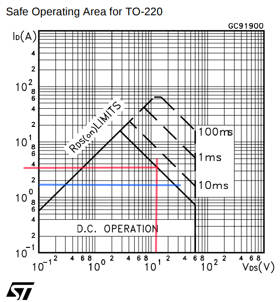
My load for this breadboard test is just a simple LED+resister, so the current is probably around 20mA. I wonder how the load of the LED strips will affect this MOSFET. I plan to use 2 MOSFETs with each controlling a single LED strip. Earlier, I measured the A/C draw for a single strip as 40-45w. Since I don't really know what I'm talking about, I'm going to assume the strips draw a maximum of 45w at 12vdc, or a little over 3 amps.
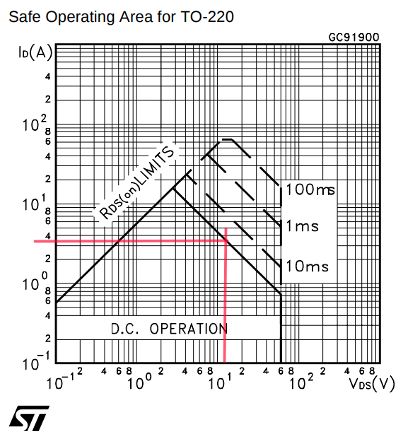
Now we're off to the races with the datasheet for this MOSFET. I've watched or read several discussions of how to use a MOSFET datasheet, but ... you know. This datasheet has a nice graph for the "safe operating area". That sounds good.
![]()
It looks like it can handle a little over 3A of 12v supply, but it's also pretty close to the margin. Let's try something else. ST provides a smart phone app called "ST MOSFET Finder" that will let you do a parametric search to find appropriate ST MOSFETs. When I put in the parameters I've just discussed, the MOSFET I planned to use is not among the search results. Drat. I guess I have no choice but to actually measure the DC load of one of those strips. Wait right here.
Things are looking better. With the power supplies that came with the strips, they are drawing 1.5A @ 12.6V, or <20W DC. That puts us well within the safe zone.
What about heat? This guy's video provides a pretty clear explanation of how to calculate that from the datasheet. Following his calculations, I get about 1/4 watts of heat and about a 15 C rise in temperature with no heat sink. I doubt that it's ever been as warm as 50 C in my garage. 15 C + 50 C == 65 C is well under the max operating junction temperature of 175 C, so I think I just have to worry about melting something in the case I use to mount these. I'm most likely to use a fairly standard wall-mounted electrical box. The common blue PVC boxes available in the US are typically rated for 90 C conductors. That seems like plenty of margin.
Over-engineered LED strip controller
Way too much stuff to light my garage MY way.