Close
0%
0%

PROMer

Yet another manual programmer for old fuse PROM chips

Similar projects worth following
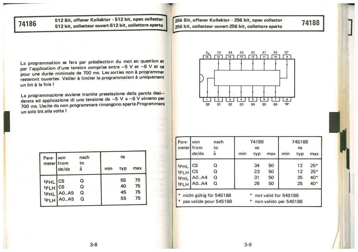
Nothing fancy here, just a circuit to burn some 74188/K155RE3/DM8223N because this is not supported by most universal programmers.
This is really in the retro category because these chips appeared in the early 70s before PAL/PLDs were a thing and they are pretty easy to program by hand, without crazy algorithms... once you figure it out !
I thought about making it with a Pi but wiring it would be faster and I didn't want to spend time with software... Not yet, since I don't have many to burn.

Oh, you ask why I would bother ? Because 7 segments decoders are often limited to BCD and it's pretty cool to have arbitrary 5-inputs logic with no software and the accompanying obsolescence. It could be handy for hassle-free address decoding as well.

I'll see if I can later adapt the circuit for the 256×4 PROM (74187/K155RE23) for other purposes.

Logs:
1. References
2. First casualties
3. Design considerations
4. Firing up an old PROM Programmer
5. BLANK


Decoding hexadecimal to 7 segments has been a long story, that has been brought back to life with the #Discrete YASEP and gave life to the #PICTIL and #DYPLED ... but it was still not satisfying because they are really modern.

Hexadecimal decoding chips are not easy to find but a smart guy solved this :

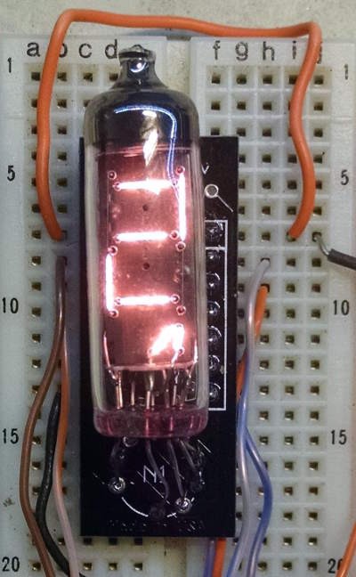
Numitron replacement of TIL311

I had been interested in Numitron displays lately and this one gave me a critical hint with one of the pictures:
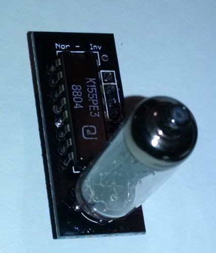
The decoding chip is actually a PROM : the K155RE3 is a Russian equivalent of the SN74188. Each segment draws up to 20mA but can work at a slightly lower current, so this is close to the circuit's limit but still manageable.

The 5 address lines are enough for a hexadecimal decoder. The extra line could be used for "reverse polarity", as hinted by the jumper labelled by the silk screen "Non-Inv". Another use would be a backup area if the first half contains an error (errare humanum est). No idea how the 8th data bit can be used though. (log 5 says leading-0 cascading)

I could find some of these parts AND information about the programming procedure, thanks to several people who did it as well !


One awesome advantage of having custom decoder chips is the ability to extend the "vocabulary" as well as remapping the pins to ease routing of the PCB traces.

Small and fast PROMs are useful for quite a few other purposes, such as small FSM, address decoding, translation of register number (in the #YGRECmos ), so having my own burner is pretty handy. I have a number of PAL22V10 but they are often overkill and it's not easy to generate the JEDEC programming files... My MiniPRO TL866A can flash the PAL but without a JEDEC file, they are quite useless.

.

  • BLANK

    Yann Guidon / YGDES03/18/2018 at 12:02 0 comments

    The PROM has 1 extra input pin and 1 extra output pin.  There is one clever way to use it !

    • Extra Input Pin : BLANK if input number is 0
    • Extra Output Pin : active if input number is 0

    This way, the decoders can be chained and leading 0s can be blank'ed.

    A simple switch tied to the MSB will select if leading 0s are blank'ed. Just like #DYPLED !

  • Firing up an old PROM Programmer

    agp.cooper08/21/2017 at 15:06 1 comment

    Guest Post

    This is a guest post for Yann.

    Firing up an old PROM Programmer

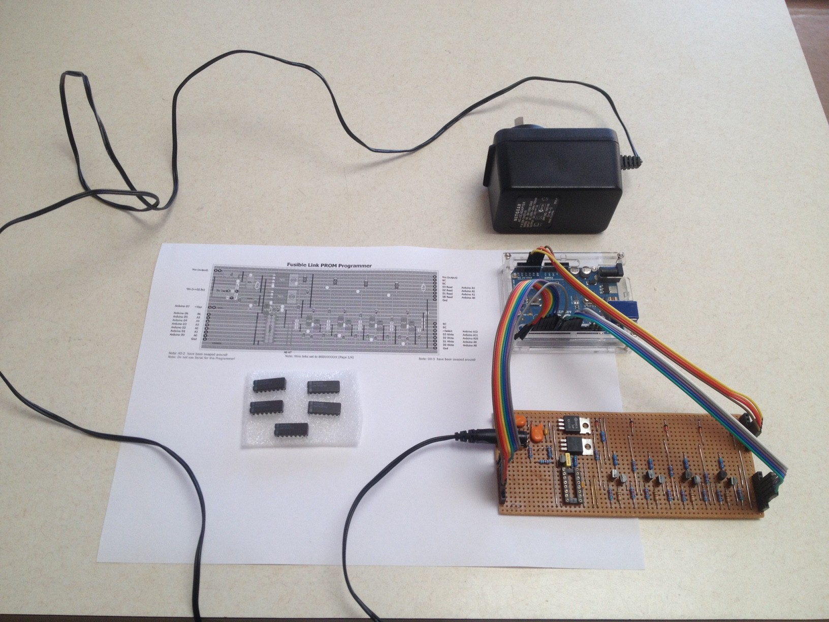
    I built a PROM Programmer for my Weird CPU a year or two ago:


    My PROMs were the 74S571 rather than the 74188 that Yann is consisdering, but really that is not material for this post.

    Programming Guides

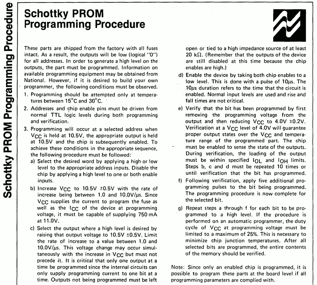
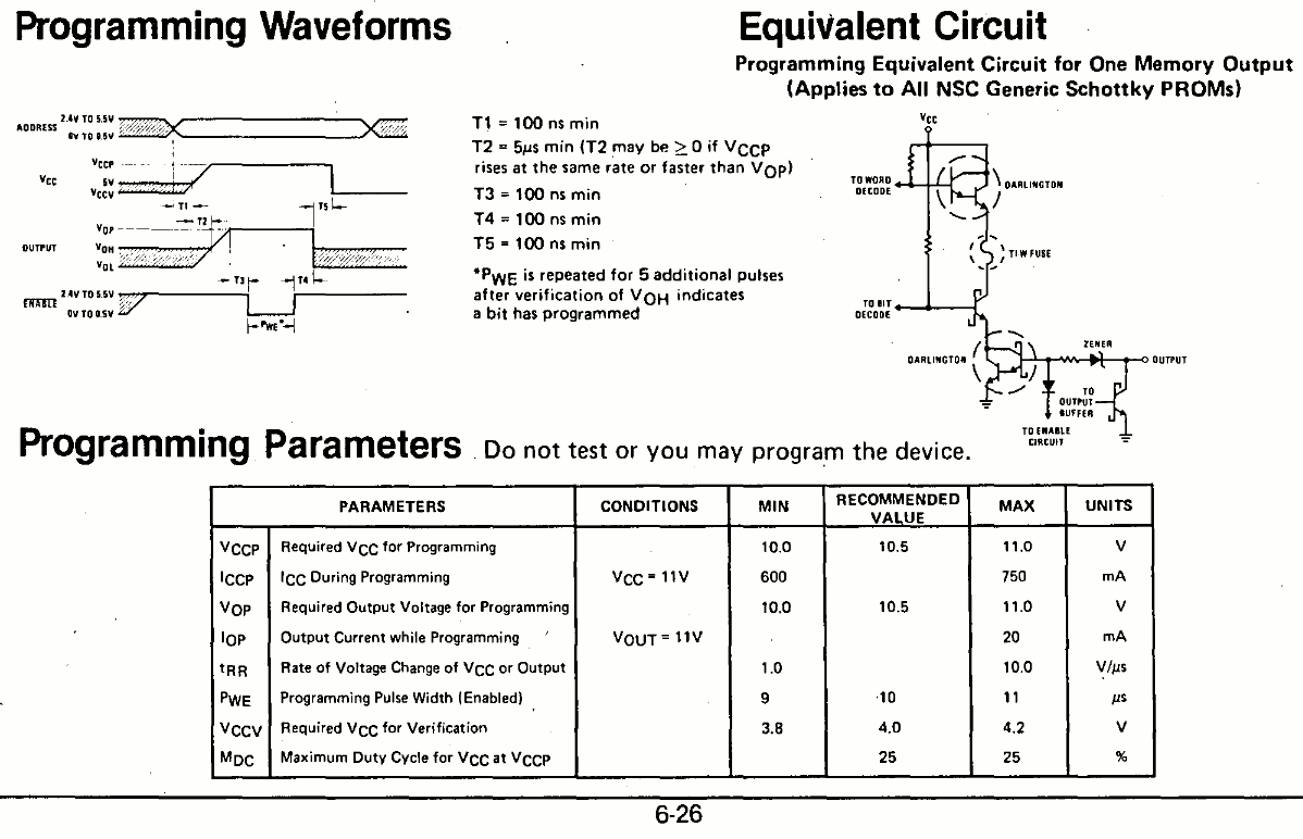
    I have looked at the programming guides for the various PROMs, although the programming guides are sometimes quite different (surprising!), I feel safe to say that if the PROM technology is the same and the programming voltage is the same, then the programming guides would be interchangeable.

    The programming guides however do suggest problems with the technology which really do need to be managed.  The main one is over heating of the chip during programming cycle. The second one is the programming voltage rise time.

    The main conclusion is that you should drive your PROM Programmer with an Arduino or similar if you want to follow a programming guide. Even if you don't follow the programming guide exactly you are still better off with an Arduino managing the programming cycle.

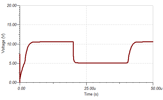
    For Ti-W technology (Yann's and my device) the voltage  (10.5v) pulse rise time needs to be between 1 us to 10 us (i.e. between 10V/us and 1V/us).

    The nominal programming duty cycle for both devices is 25% (i.e. no more than 25%).

    Generating the Voltage Pulse

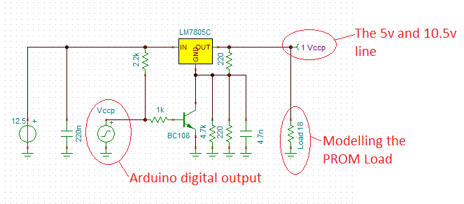
    The easiest way to do this is to use a 12.5v or higher voltage supply (but it must be able to supply 1A) and a voltage regulator. All that needs to be done to the voltage regulator is to adjust the feed voltage to switch the voltage. We can do this with a transistor. In order to control the voltage pulse rise time we just control feedback voltage rise time. Here is my design:


    The 2k2 resistor between the power supply input and the Vccp input is designed to ensure the output voltage stays at 5v if the Vccp connection (now call VPP) is broken. The 4.7n capacitor controls the pulse rise time. The 4.7k and the 220R resistors are for fine tuning of the 10.5v voltage output. Here is the voltage pulse signal:


    The pulse rise time needs to be in the order of 1 us to 10 us (check it is!).

    Programming the Bits

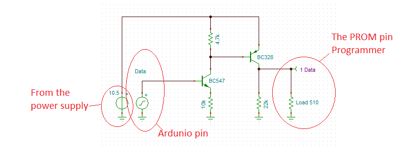
    To limit current into the PROM output, the bit programmer (yes the device is programmed one bit at a time) needs to be able to go tri-state when off. Here is my design using common transistors:


    I used transistors because they can handle the current with low voltage loss. The BC328 is perfect for this application. The BC547 just needs to be high gain.

    Yann asked about the 10k emittor resistor? It increases the transistor input impedance and limits the transistor current.

    Sensing the output of the PROM

    The final version is a little slow (~2us) but works well:

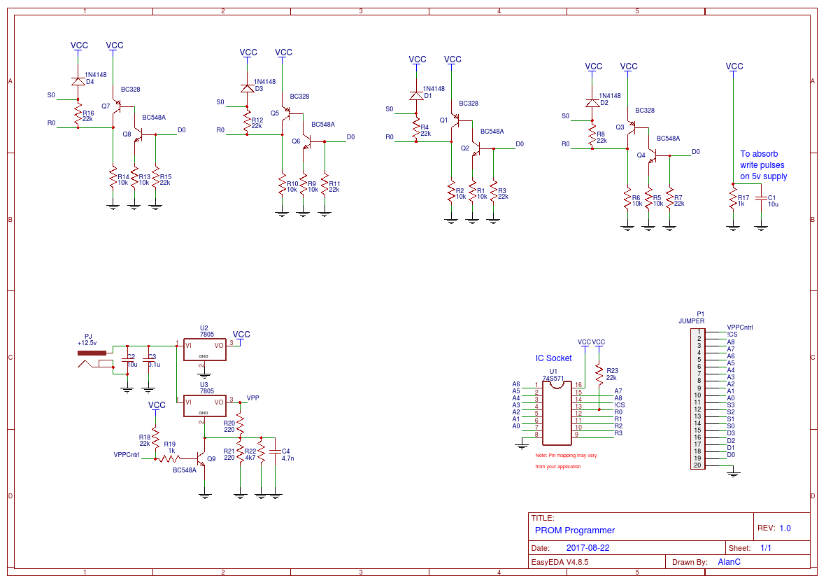
     I redrew the schematic just to make things clearer:

    As you can see the 74S571 is a 4 bit data word while Yann's PROM is an 8 bit data word.

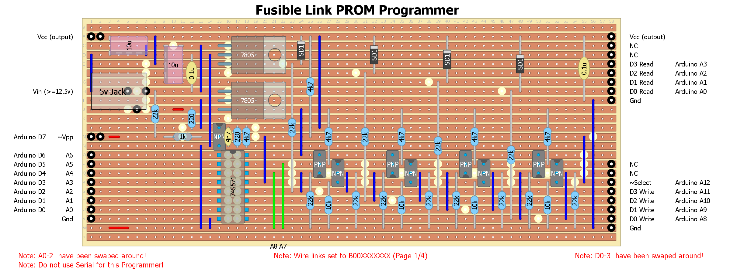
    Here is my strip-board design for the PROM Programmer:


    Note the Arduino Pin assignments will change for the published PROM Programmer code.

    The top voltage regulator is for the 5v logic, the bottom regulator is for the programming voltage pulse. The green links are for different PROM pages, as only 128  bytes are (currently) programmable at a time.

    The main problems with this design is the voltage regulators get hot if the programmer is left plugged into the power supply. The second problem is the need to connect (i.e. wire up) the programmer to an Arduino each time it is used. Better is a Nano was integrated into the design.

    The Programmer Code

    I rewrote the PROM Programmer code. It is pretty hard to write code that has to work the first time! But this code is better. It reads the PROM code first and they you have the option to burn either the high or low nimble:

    // PROM Programmer:
    //   This code programs the LOW nibble of "ROM" data to the 74S571 PROM.
    //   The "ROM" data is in the source code.
    //   A factory PROM is all LOWs and the Programmer writes HIGHs on bit at a time.
    // The programmer has pull up resistors on VPP and /CS...
    Read more »

  • Design considerations

    Yann Guidon / YGDES07/16/2017 at 21:30 0 comments

    (moved from the project description page)


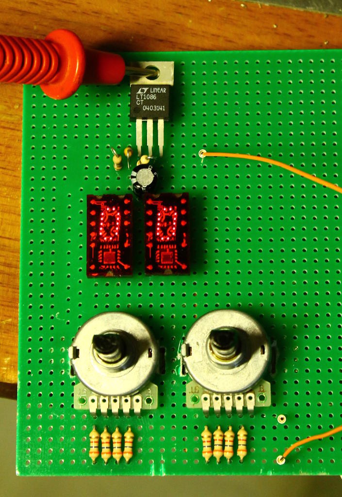
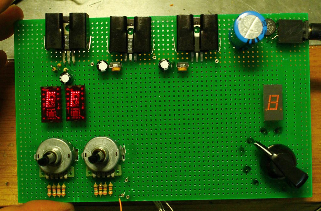
    Since I want to program both 74187 and 74188, I need 8 bits of input and 8 bits of output. I started with my favourite parts: a couple of hexadecimal encoding wheels and a couple of TIL311 for the address bus.

    The data bus is a bit unusual : one of the data bits is shorted to 0V, so I use a 11-positions rotary switch (leftover from the #Clockwork germanium discrete clock project) to select the desired bit. For the lower nibble (in the 74187 case) I might add a TIL311 for inspection of the output but LEDs should be enough otherwise. A 7-segments module is used as well to check the output.

    The fuse is blown when the power supply is raised from 5V to 10.5V. The different voltage sources are isolated by diodes so approximately 5.6V and 11.2V are required. Add to this that the TIL311 are undervolted at 3.6V... That's a few diode drops, but too close to the margins to use LM317s.

    Starting from 12V, two diode drops provide about 10.6V but this is not accurately regulated and might affect the programming. A 14 or 15V input source would allow the use of a LM317 so the power supply would be a 12V unregulated "wall wart" (let's see what I have in stock).

    From 10.6V down to 5.6V, another LM317 drops 5V. This is probably the one that dissipates the most power.

    Then from 5.6V to 3.6V, two volts are dropped but the TIL311 power rail does not need a tight regulation so a string of 3 silicon diodes would do.

    The TIL311's current is measured in the 125mA ballpark (around 60mA per module) and this is the most consuming circuit. The power drops are: 1/4W for the 2V drop and 0.7W for the 5V drop. This is significant but still in the range of the circuits made in the 80s... The good side is : this current keeps the LM317 in the regulation range. In the end, the wall wart must provide at least 200mA (probably rated at 500mA) and most of it will be turned into heat.


    I found several LT1086, in fixed and adjustable versions, with are low dropout versions.

    Minimum load current less than 5mA, input voltage is high enough (25V max) and the dropout does not exceed 1.5V at max current. That's just enough margin for the input regulator (11V) and the TIL311 rail (5.6V to 3.6V) without weird hacks.

    Let's start with the 3.6V rail : I got the regulator and I just have to add a couple of resistors to set the voltage. I find that the ratio of resistors is 2.88 so if I set one resistor to 1K Ohms, all I have to do is find a 2.88K-1K=1.9K resistor. Fortunately this is close to the standard 1.8K value, and the voltage does not need high precision. There is also a need of capacitors but that's not a critical consideration... 100uF/25V will do, I have a significant number of them in stock. Ahem.

    The 1.8K and 1K resistors give about 3.59V which is pretty good :-)

    This works quite well when you don't mistake a fixed with an adjustable version. And it also made me devise a little trick to calculate the resistors : just convert the volts in kiloohms :-) With a 1.2K resistor for the adjust pin, if I want 3.6V I need 3600-1200=2400 ohms. This is less reliable because of the disturbance of the adjust pin's current but we'll add a trimpot later.

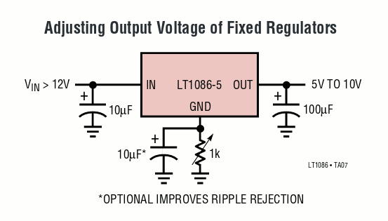
    For the 5.6V part I'll use a different trick that the datasheet suggests:

    If we consider that 1K provides a 5V swing, 1K/5=200 ohms will provide the required 1V swing :-) That's possible though if I haven't burned the first LT1086-5 that I mistook for an adjustable version for my first attempt...

    (Now I realise I could have used this trick because I have 3.3V versions and that would have saved one resistor)

    With a 330 Ohms trimpot, I can vary the output from 5V to 6.8V :-) This amounts to about 180 ohms per Volt so a 1K resistor will increase the output by about 5.4V, resulting in 10.4V.

    Using a 990 Ohms and the same type of 330 Ohm trimpot, I get a range of 9.6V to 11.2V, which is perfect. The 10.5V output is obtained with the trimmer at approximately half position.

    For the PSU, I have a 12V 500mA AC block...

    Read more »

  • First casualties

    Yann Guidon / YGDES07/16/2017 at 21:08 0 comments

    I already damaged 2 TIL311 :-(

    I wonder what happened but I suspect my new fancy digital lab power supply. Turning it off while the circuit is still connected could send spikes that damage the pins...

    So I have to implement the power supply ASAP or I'll burn my stock of TIL311 quickly :-/

    Lesson learned : TIL311 are quite fragile...

  • References

    Yann Guidon / YGDES07/16/2017 at 10:57 0 comments

    I've been lucky to find several similar circuits on the web, as well as datasheets. Here's a list for those who are as curious as me...


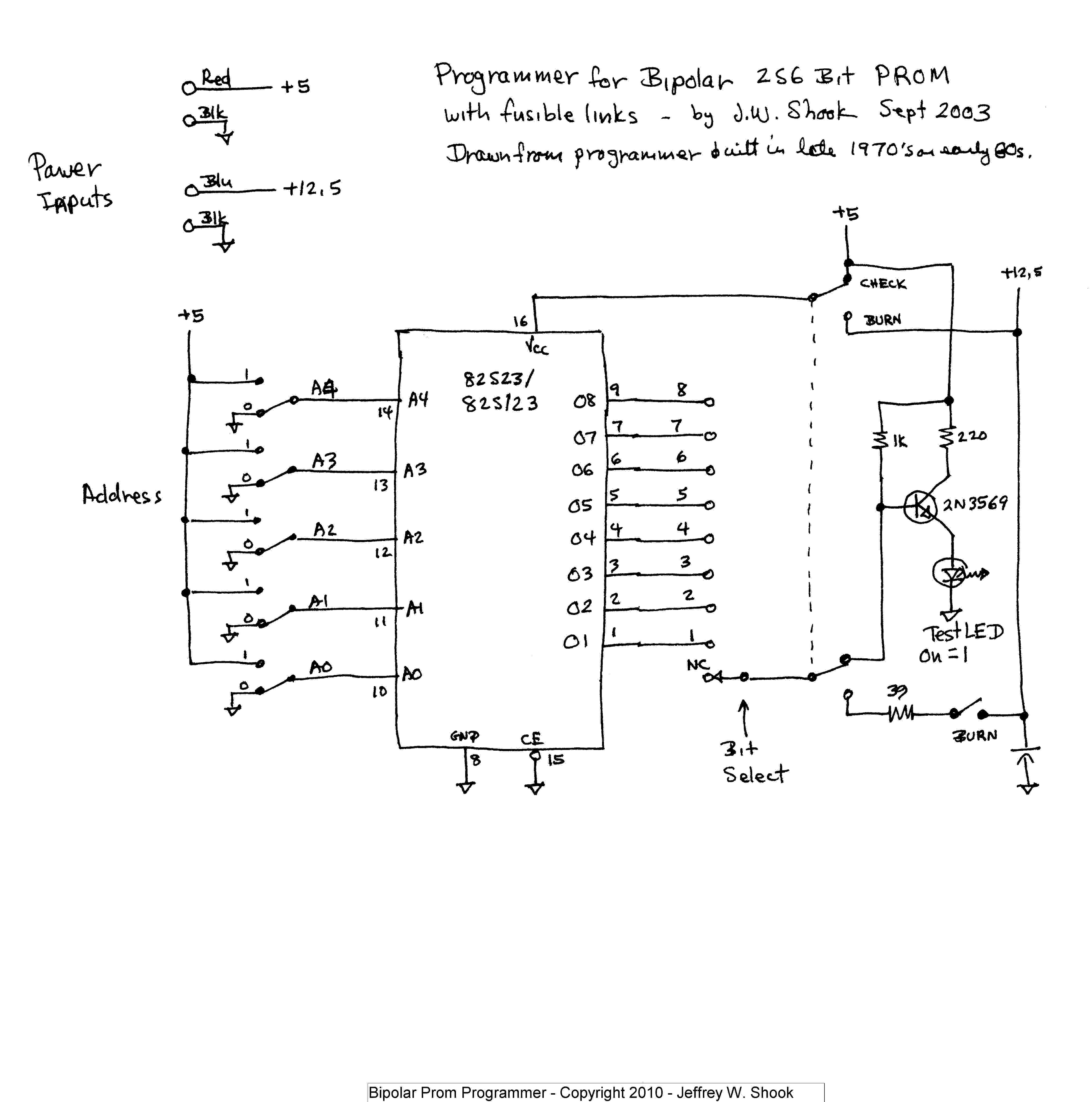
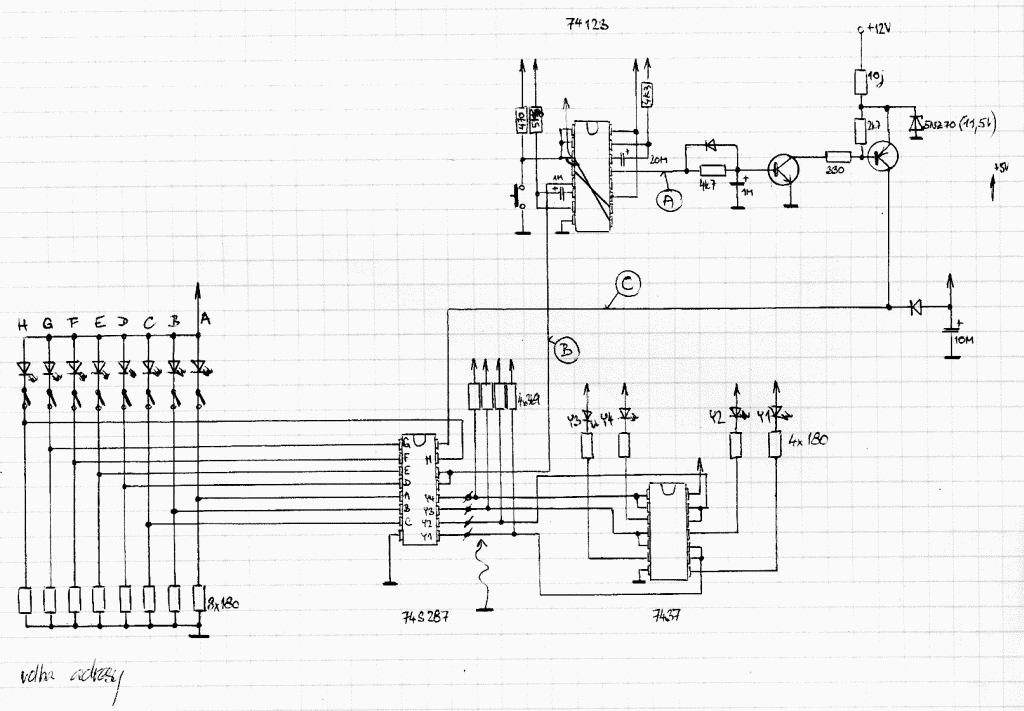
    • I once found a page but it is now closed. Fortunately I saved the page "just in case" and here is the programmer's circuit:

    I'm not sure to understand most of it but it contains some interesting ideas.

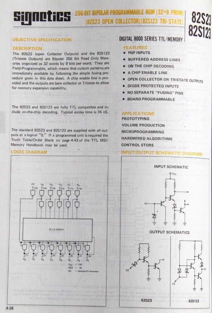
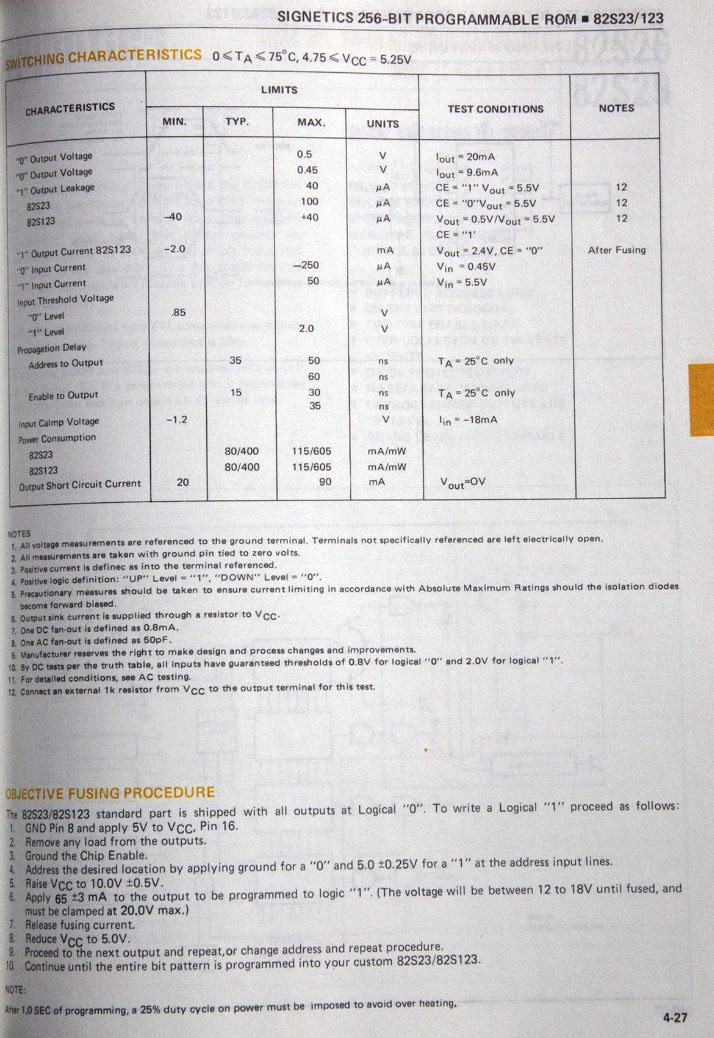
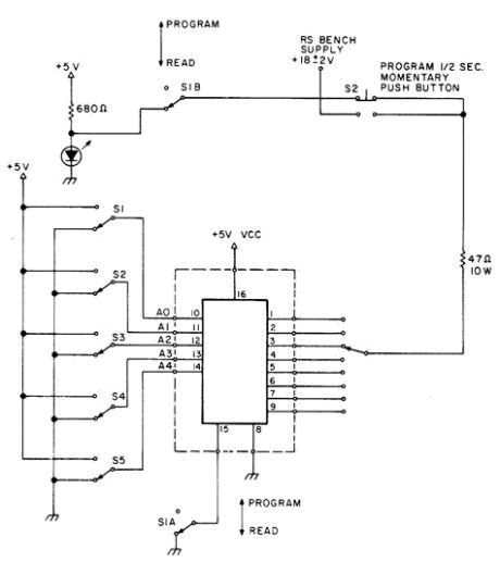
    Note: this schematic applies to the 82S23 which has a particular, slower programming cycle, with a 1s pulse, limited to about 65mA (hence the series resistor and the push button), as found at http://www.avrfreaks.net/forum/scheme-prom-ic-programmer :
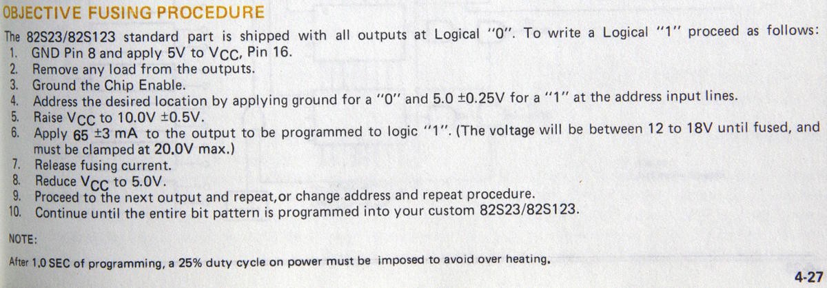

    Yup, Vpp is also applied to the data pin, not Vcc...

    Note that current-limiting the Vpp node should be possible with a suitable base resistance...


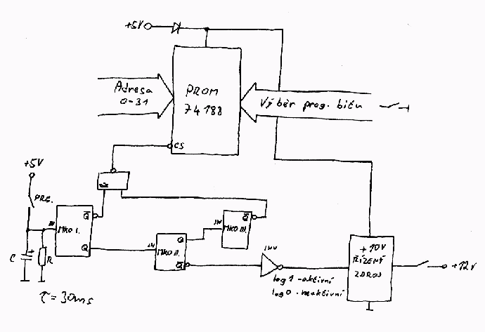
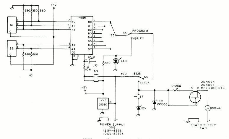
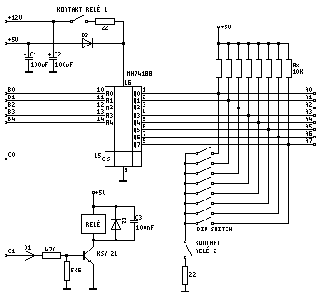
    • Another one (source forgotten, maybe from one of the above broken links ?)

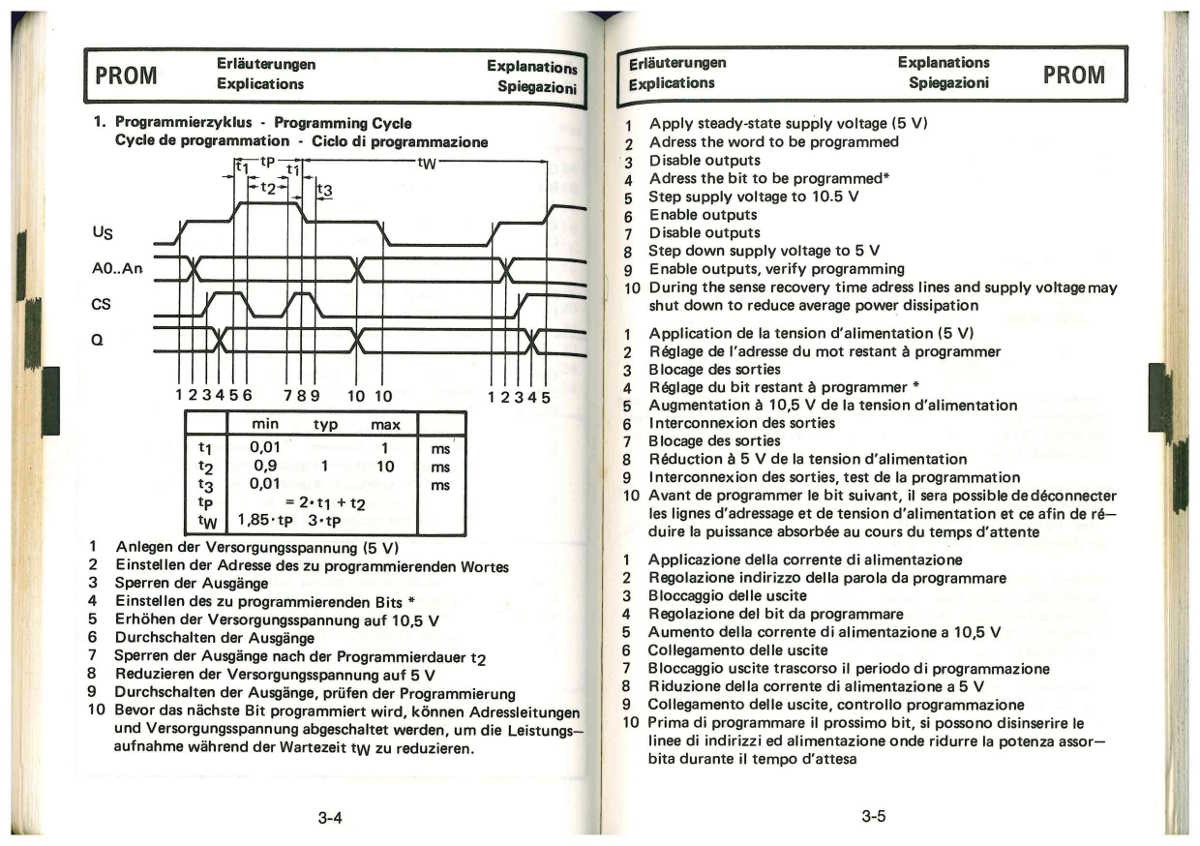
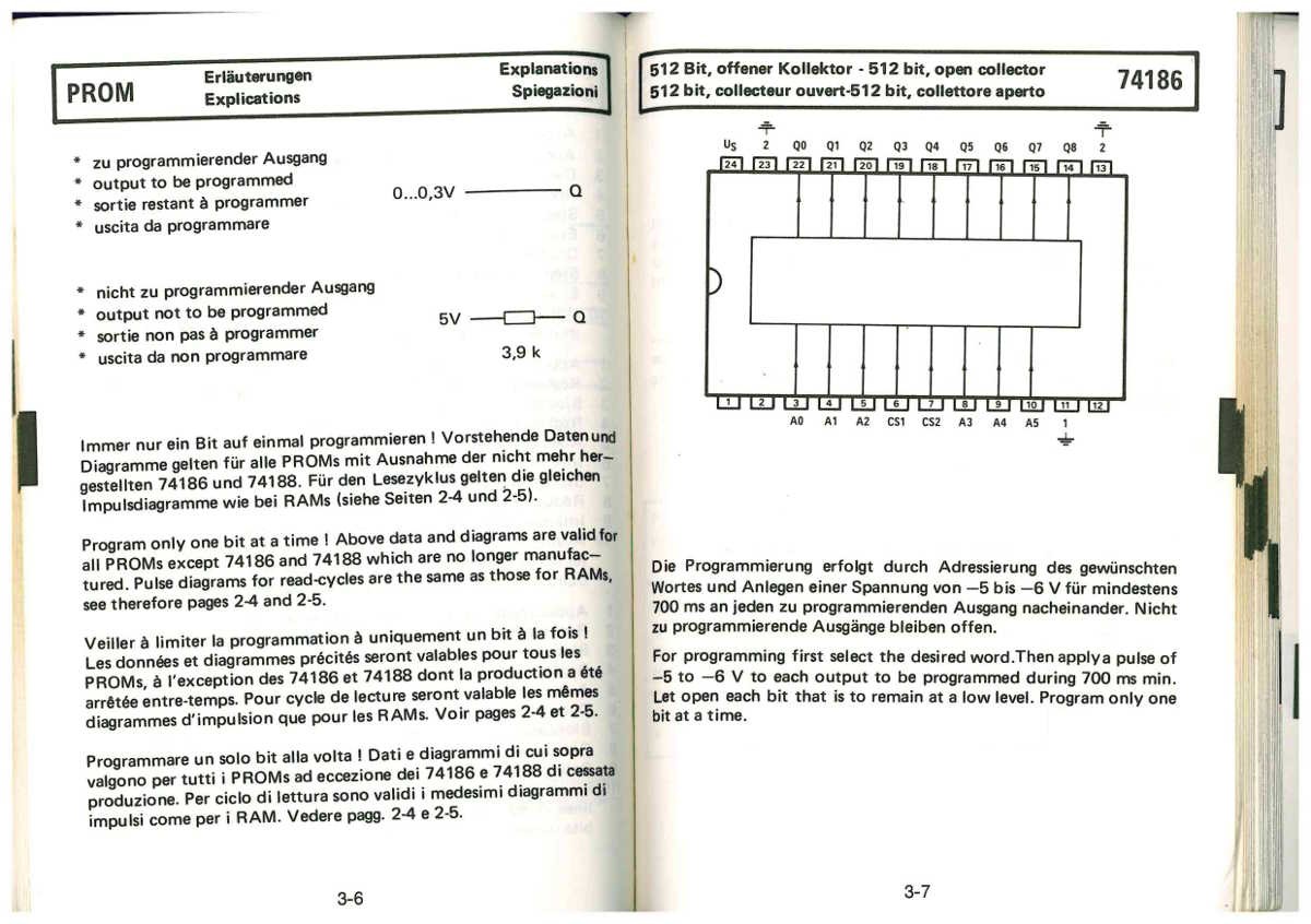
    • Another set of pictures I had saved but couldn't trace to the origin. I appreciate the (quite clumsy) translations :-)

    (ok it's obviously a translation and redrawing of the original TI datasheet but it's still nice)


View all 5 project logs

Enjoy this project?

Share

Discussions

Similar Projects

Does this project spark your interest?

Become a member to follow this project and never miss any updates