Board
schematic

( Pin 4 is the shield of the connector )
board
Case
I built a case out of 4 parts, which I cut out of an woodboard with a lasercutter.
There are two things I didn't liked about that case: The corners and that I needed to make a hole for the USB-Cable.
So I designed a second version. Thats how I built it ( the buildingprocess of version 1 is similar ) :
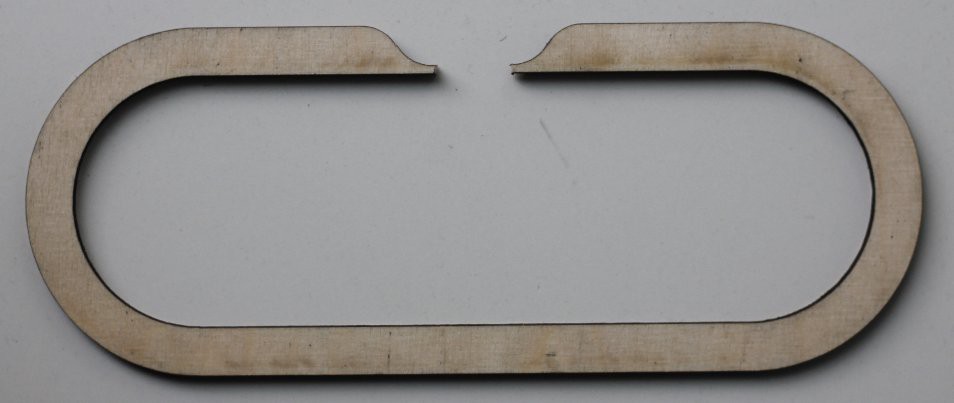
The parts for the case version 2
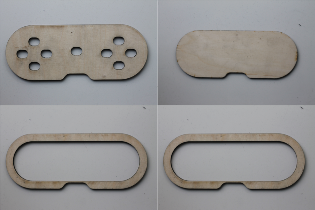
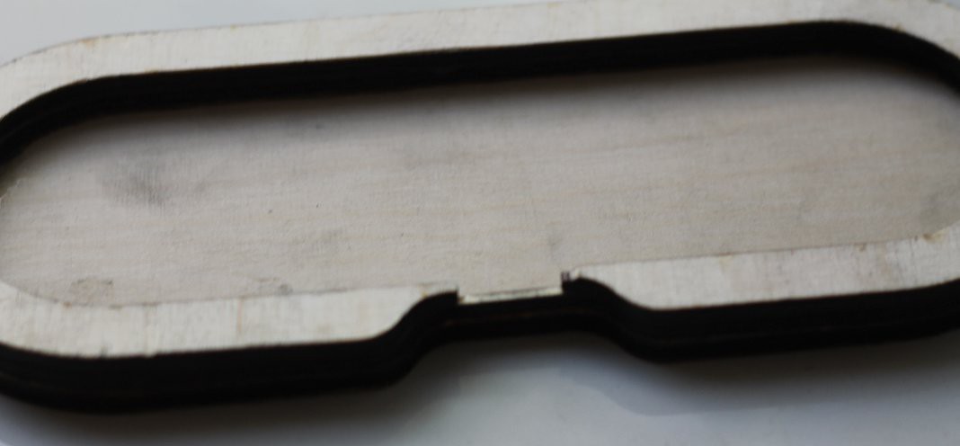
I cut a piece out of one of the middle parts for the connector.
Next I glued all parts except the top one together.
And painted all parts with clear paint, to ninimize dirt on the controller.
Next I cut away the corners of the board, to make it fit into the case.
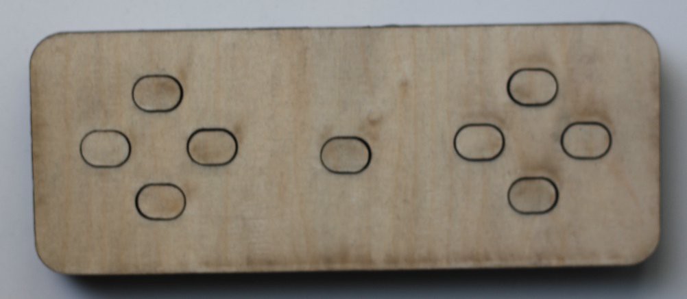
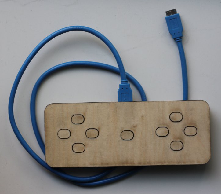
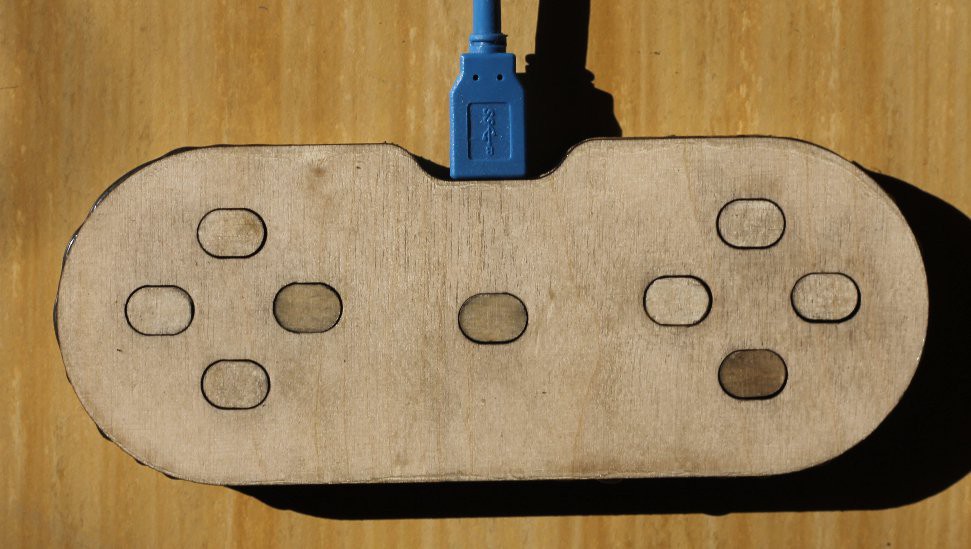
And then I glued the board in the controller and the top on it.
Unfortunatly the most buttons didn't work. The reason for this is probably, that I orderd other simular buttons, for the second board by mistake.
 sisam
sisam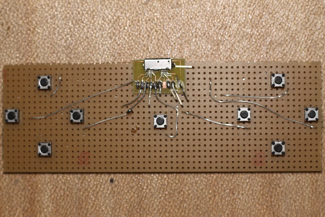


Discussions
Become a Hackaday.io Member
Create an account to leave a comment. Already have an account? Log In.