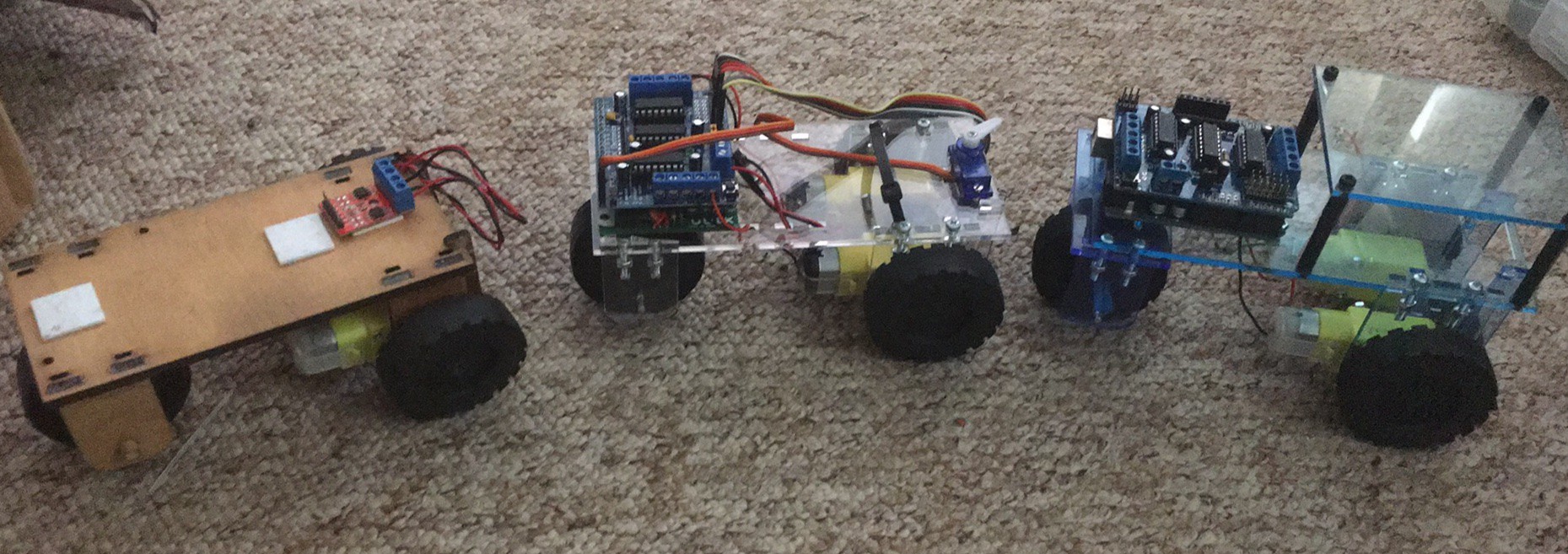
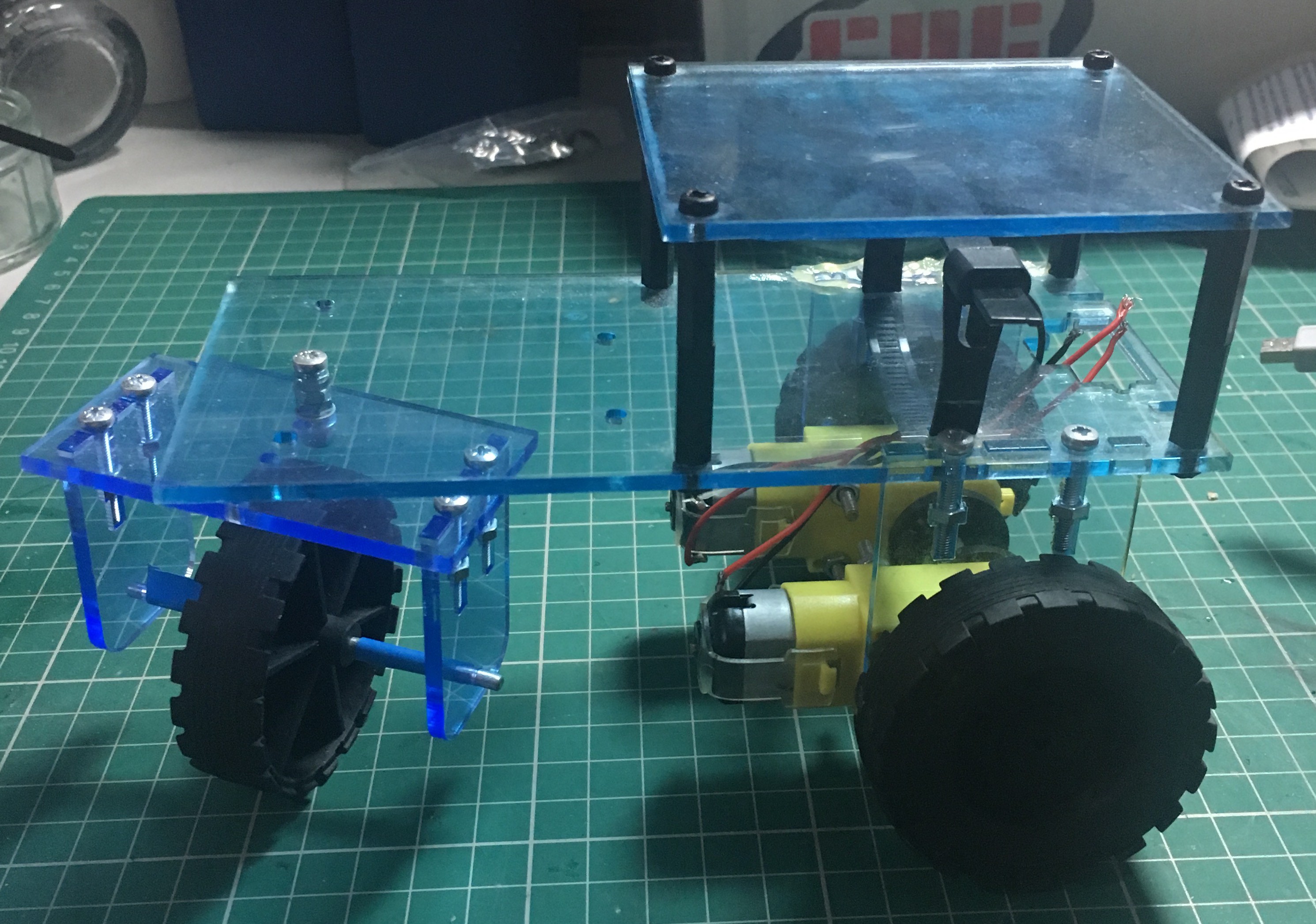
The history of E.R.N.I.E, from left to right: The first version that was produced for the headstart event, The fully reusable version of ERNIE that is available on github, The future improved ERNIE that features a caster for the rear wheel as well a platform to mount extra electronics.
E.R.N.I.E v1 - The past
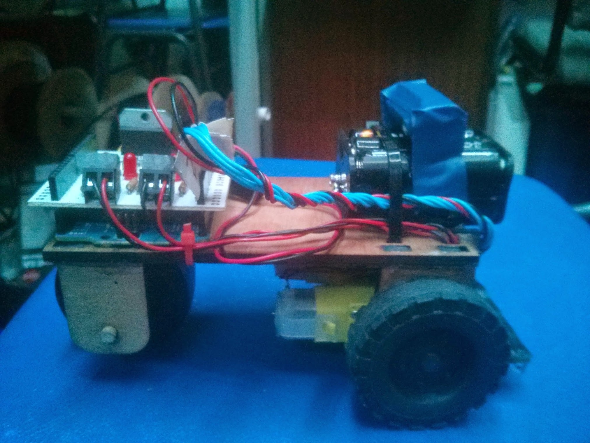
The first version of E.R.N.I.E was produced in a week for the first headstart event at the University of Surrey. Five units were produced, one completed unit for demonstration and 4 kits for students to assemble. It was made out of wood due to that being the only material on hand and meant we would make any last minute modifications if necessary. The pieces were hot glued together making the chassis very robust but could not be disassembled for future classes. The sensor bars for this version of E.R.N.I.E were created on stripboard, which caused many problems for students who were soldering for the first time. In this version of the chassis the motors are held on with zip ties! The wheels need to be drilled to allow them to fit directly onto the motors and the large dowel. The rear wheel had too much traction and had to be wrapped in electrical tape to allow it to slide.
E.R.N.I.E v2 - The present
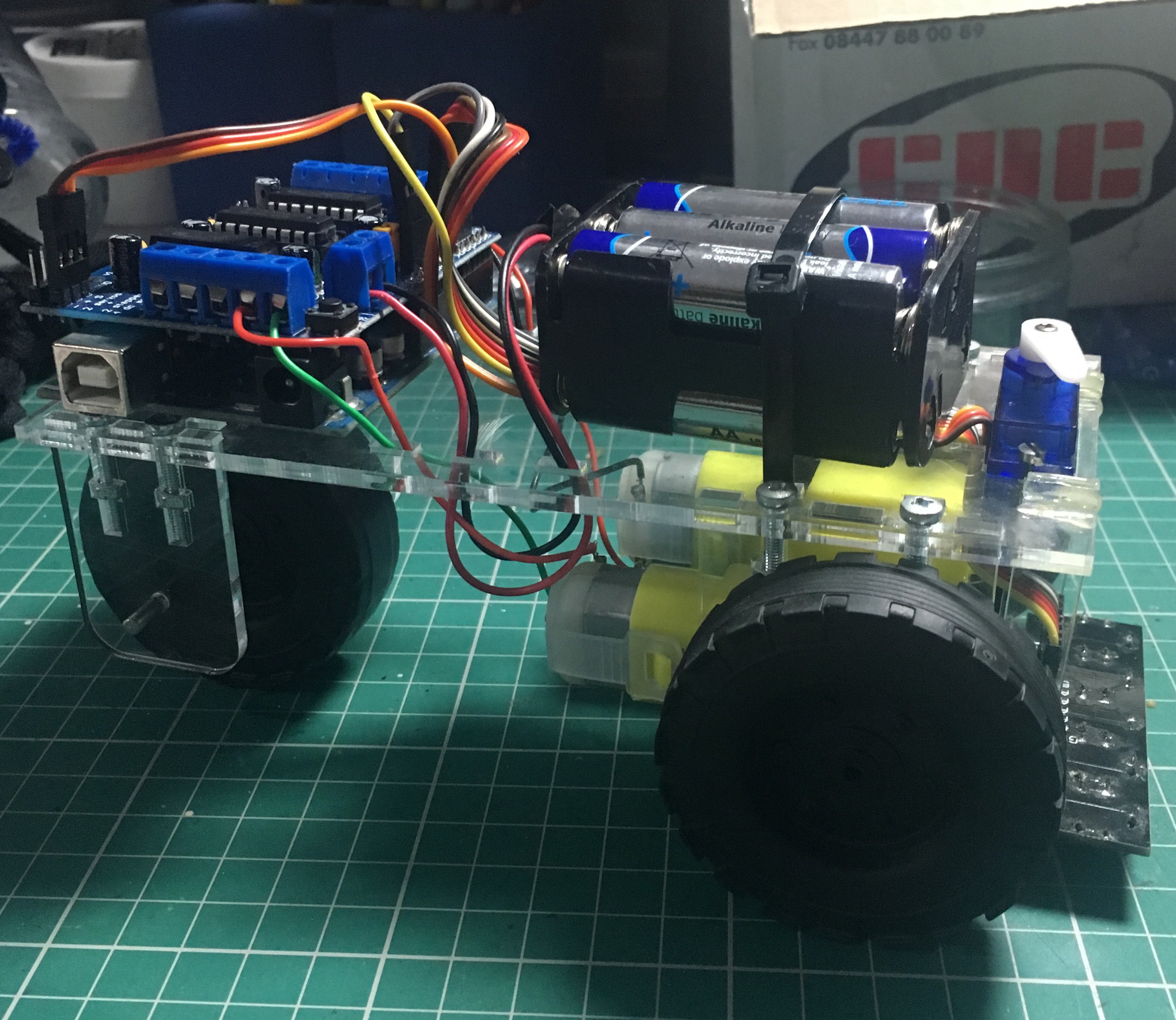
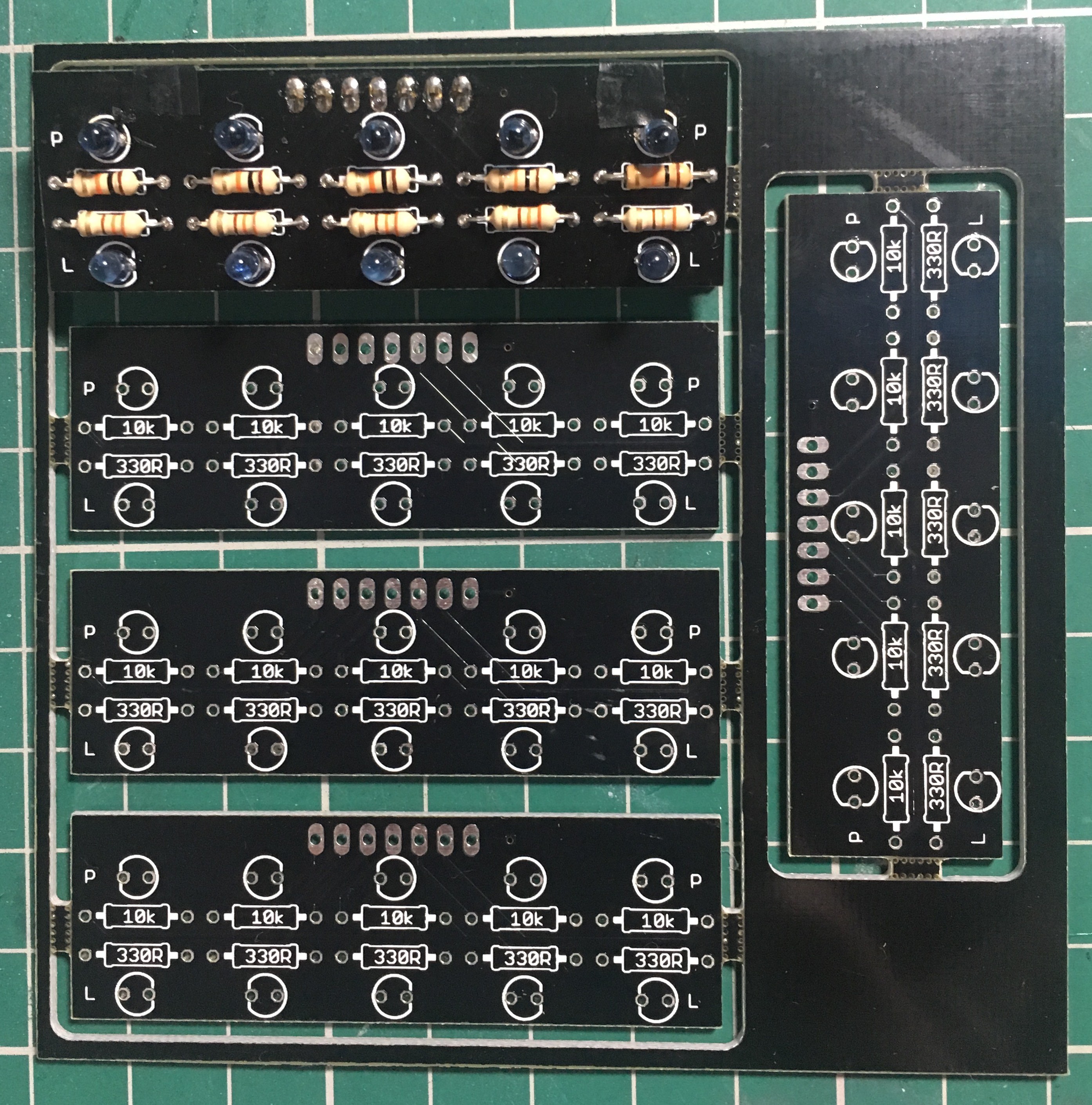
For the following year, more E.R.N.I.Es were required, this time eight kits were needed. For this second run of E.R.N.I.Es some improvements were made. The chassis is now made of acrylic as it has a more professional look and no longer requires glue for assembly. Using the same method as the MeArm, T slots are used to hold captive nuts in the acrylic such that it can be screwed together and taken apart again. This includes proper screw mounts for the motors. The rear axel is now metal, and appropriately sized, unfortunately tape is still required to allow the robot to turn. There is now also a slot for a front mounted servo with the intention of using it together with a ultrasonic distance sensor for obstacle avoidance in a future class. Due to the problems caused by the strip board sensor bar, a proper PCB was created for this version. 5 sensor bars were panelised onto a 10cm x 10cm PCB this resulted in a final price of only £0.45 each.
This version of the chassis is what is currently available for download and has been very well tested over several year. The sensor bars work very reliably and the chassis is extremely rigid with the sensor bar holders being the only exception. Around 20 of units of this design have been build.
E.R.N.I.E v3 - The future
Driven by the desire to sell E.R.N.I.E kits, v3 is currently in the work. Taking the lesson learnt from the previous two iterations the following improvements are being implemented:
- Rear caster - In order to remove the reliance on tape to make the rear wheel slide, v3 will feature a caster style wheel. The caster as shown above does not function particularly well. It does not turn properly and has a significant wobble, this requires further development.
- Optional platform - v2 of the chassis had very limited scope for use outside of line following due to a lack of space to mount any other electronics. To solve this in v3, there is now an optional platform that can be installed above where the battery lives.
- Sensor bar holders - The major problem with v2 is that the sensor bar holders snap easily. To solve this in v3 the sensor bar will be redesigned with two screw holes and the new holders will attach to it in the same manner the motor mounts do.
- Axel - A new method needs to be devised for retaining the rear axel that does not involve electrical tape. O-rings are a potential candidate for this, but this has yet to be explored.
- Servo - A notch has been added to the servo mount to prevent damage to the wires when installing it.
 Sebastian Goscik
Discussions
Become a Hackaday.io Member
Create an account to leave a comment. Already have an account? Log In.