 The idea
Surrey EARS run an Arduino course every year. When designing this course we needed some sort of extravagant project at the end to put everyone's newly learnt skills to the test. The idea we settled on is a traffic light network. Each student is tasked with constructing one of many traffic lights which are all connected along a common bus. As the students enter the room they are greeted with a complex line following robot track with multiple crossings. Each student is given a sheet that defines and when and where their traffic light is. It is up to the class to implement all the lights (20 in our case) to prevent the line following robots on the track from crashing into each other.
Implementation

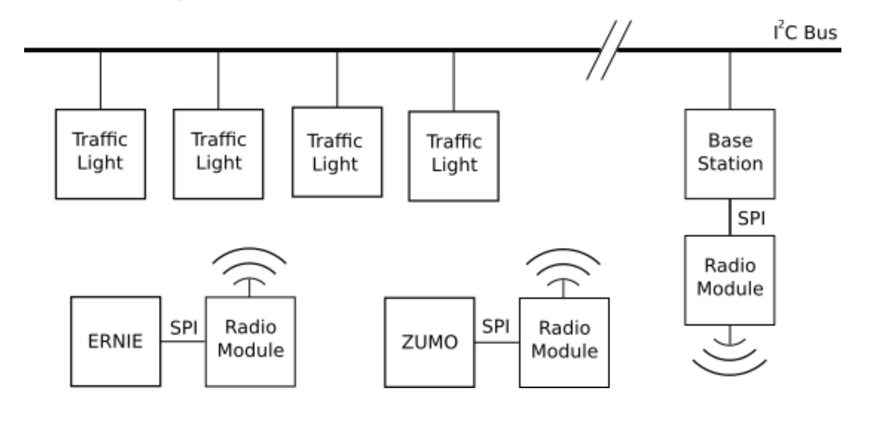
Each traffic light is a relatively simple circuit consisting of an Arduino and 3 LEDs (and resistors) on a breadboard along with a connection to the common bus. Earlier on in the course the students learnt how to use I²C, they will now get to apply what then learned and create a slave device on a shared I²C bus. There is then a base station unit that serves two purposes. Firstly it sends a regular heartbeat along the bus on the general call address which is used to synchronize all the traffic light nodes. Secondly it allows the robots on the track to query the current state of a traffic light. The robots connect to the base station wirelessly via a NRF24L01. The base station was implemented on a ARM mbed board due to the fact it supports "multithreading" allowing the heartbeat to run separately from the query interface.
The base station produces an incrementing heartbeat at regular intervals. This heartbeat is a single 8 bit number that increments from 0 to 24 and then resets. This heartbeat is sent out on the general call address which is unfortunately disabled by default in the wire library that comes with Arduino. This can be remedied by using the following code after setting up wire:
bitSet(TWAR, TWGCE);
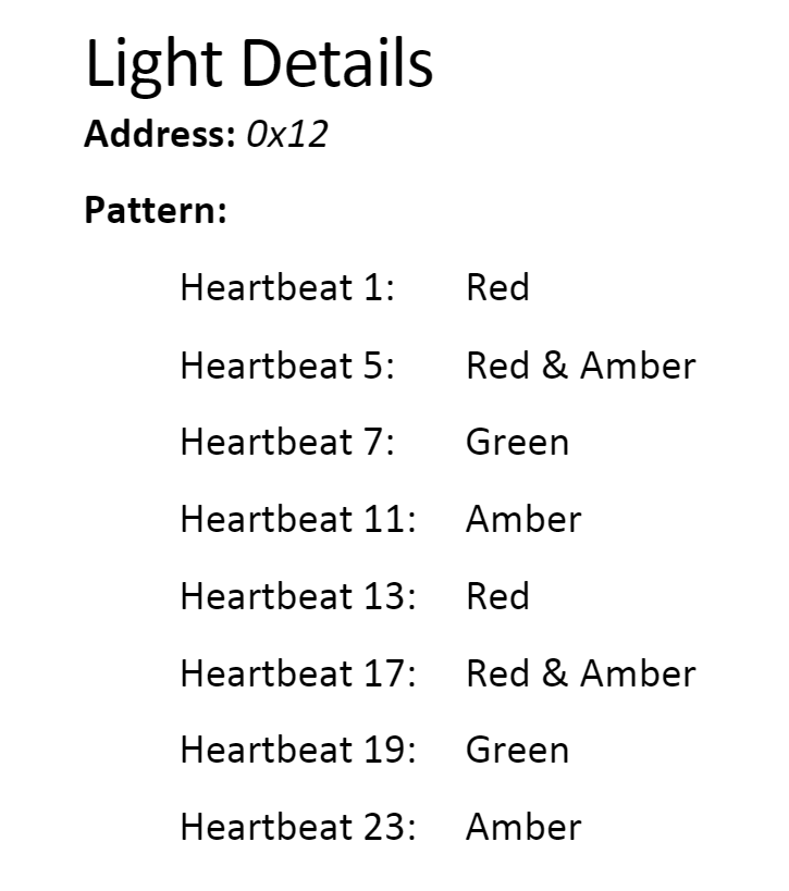
The students need to create a interrupt service routine that will update their state and attach it using the onReceive function of the wire library. Each student is given a handout at the start of the session that provides them with a unique address as well as a list of what state they should be in at what heartbeat value e.g:

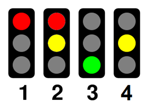
When a robot is going around the track, it will stop whenever it reaches a junction marker, a solid line across the track. This triggers all the sensors of the robot's sensor bar which is easy to detect. When the robot stops at a junction it will begin to periodically poll the base station for the status of the light it is currently at. Once the robot gets a green light it will travel forward for a set time to clear the solid line caused by the junction. Since the track is a loop the robot only needs a simple counter to know which light it is at. When the robot polls the basestation, the basestation then in turn does a read request to the corresponding traffic light. The students need to create a interrupt service routine which will return its current state and attach it using the onRequest function of the wire library. The traffic light should return a number between 1 and 4 depending on its state.

This simple use of read and write requests means the code the students need to create remains simple while covering everything they need to learn. The students do not need to worry about commands/register values etc.
Problems
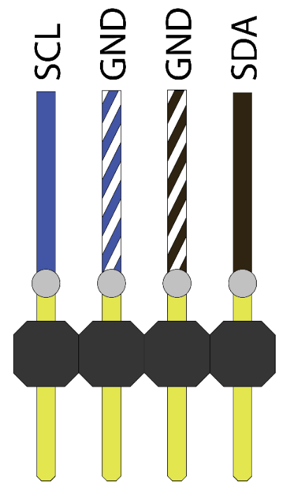
Despite what is written in multiple places on the internet about I²C only being able to go ~2m before capacitance renders the bus useless, we managed to get this system to work over 20m of CAT5e cable with crudely soldered connections, daisy chained through breadboards, every meter.

The signal quality over this bus is actually surprisingly good, the gotcha that caused bus instability was not bus capacitance. The issue comes from the Arduino, when it is unpowered the SDA and SCL lines get pulled to ground. Since this is a multi-drop bus, the second any of the students unplugs their Arduino from their laptop the entire bus fails! This leads to a lot of tail chasing during the session.
Future
The traffic light network is currently in the process of being re-engineered. Rather than using I²C, the network is being moved over to RS-422. This bus is designed to go long distances and features separate TX and RX lines. This means that should any student's node cause an issue when replying to the base station on the RX line, the TX line will still function correctly for sending heartbeats to all the other lights. RS-422 transceivers are relatively cheap and correctly disconnect themselves from the bus via a tristate buffer when they are unpowered solving the major issue we had with I²C. By using a circuit called a bias-tee (image from wikipedia) power can also be injected onto the signal lines without interfering with the data. This will allow the lights to still function when unplugged from laptops

The second upgrade the system is undergoing is switching from using NRF24L01 modules to using WiFi. The base station is being replaced with a Raspberry Pi Zero-W and will act as WiFi hotspot. The robots will then use a ESP8266 to connect to the base station. This provides multiple advantages:
- The Raspberry Pi can be be connected to a projector to display the bus status, eventually a web based user interface will be created to manage the network and to show its status. Showing which lights are missing, and which are not responding as expected etc.
- The base station can now be written in python, and by using asyncio it can be made to allow multiple "processes" (actually co-routines) to share access to a single bus. This system can easily be used to extend the base station functionality without needing to compile and flash binaries to a microcontroller.
- The base station software can now be easily tested without any hardware since it uses a HTTP REST API for the robots and this can be accessed from any computer. The traffic lights can also be simulated in software.
- The robot circuitry is now simpler, instead of a atmel MCU and an NRF radio module, just the ESP8266 is needed. This also lowers the cost.
This improved traffic light system will soon be complete and get its own project here on hackaday.io so stay tuned!
 Sebastian Goscik
Discussions
Become a Hackaday.io Member
Create an account to leave a comment. Already have an account? Log In.