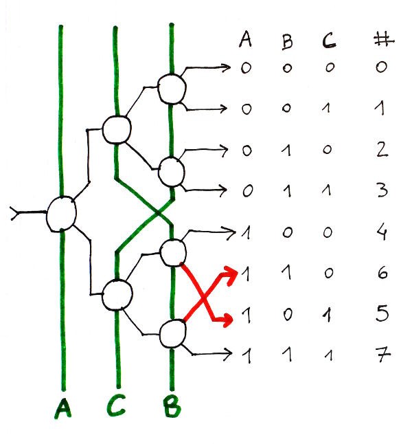
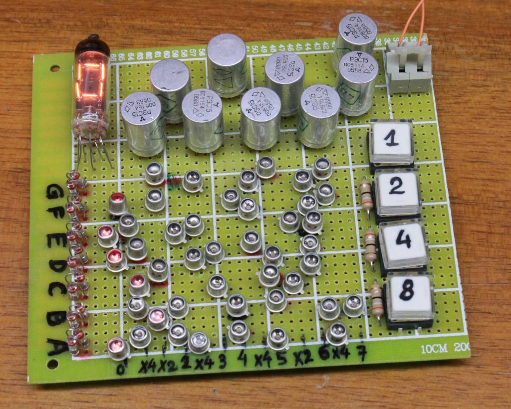
Do you remember this picture from the last log ?

OK and now, let's think again about how the diode matrix was optimised.
The short version is : the digits 5, 6, D and E are bork.

This means that my carefully optimised diode matrix is invalid. I have to swap 6 and 5 before optimising to preserve coherence...
The swapped array:

^ ^v^v^v^v^v^v (0, 8)
^ ^   ^ ^v^v^  (1, 9)
^v^ ^v v^ ^v^v (2, A)
^v^ ^ ^v^v v v (3, B)
 v^v^ ^  v v^  (4, C)
^v^v^v^v v  ^v (6, E) \ swap !
^v v^ ^v^v^  v (5, D) /
^ ^ ^    v v^v (7, F)

The new optimised array :

   v^v v     v (0, 8)
      ^  v^ ^     X4
^ ^     ^  v      X2
     v    ^ ^  (2, A)
 v  ^  v     v    X4
      ^  v     (3, B)
           v   (4, C)   (2 ^ to remove)*
 v^v  ^     ^     X4   (2 ^ to add on A and F)
^    v v     v (6, E)  (1 v to add and 2 ^ to remove, swap with 5)
    ^    v        X2    (unchanged)
 v v  ^v^ ^    (5, D)  (1 v to remove and 2 ^ to add)
^            v    X4 (2 ^ to remove)
  ^        v^  (7, F)   (2 ^ to add, reusing those of 4)
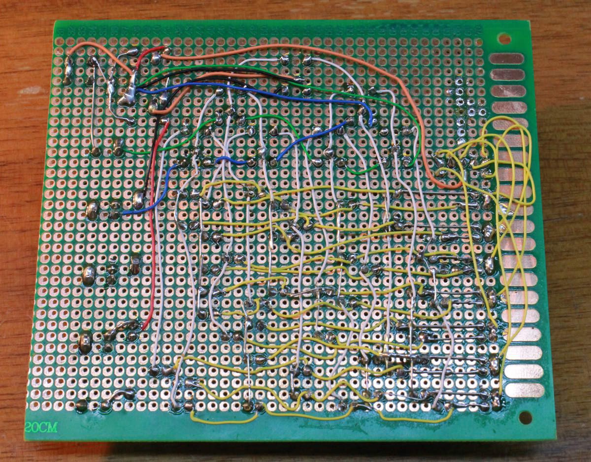
So I have to rewire quite a few diodes... Half of them in fact ! Well, not really, because some of the changes are rather symmetrical. For example, the X2 line is not changed and instead of removing LEDs from line 4, the LEDs can be rewired to line 7.
This gives you an idea of the rework that awaits me:

 Yann Guidon / YGDES
Discussions
Become a Hackaday.io Member
Create an account to leave a comment. Already have an account? Log In.
looking at the photo of display unit...
oh my God. Looks like numitron becoming a supplement (secondary) display in this case :)
Are you sure? yes | no
It's part of a whole "totally visible" design philosophy :-)
Are you sure? yes | no