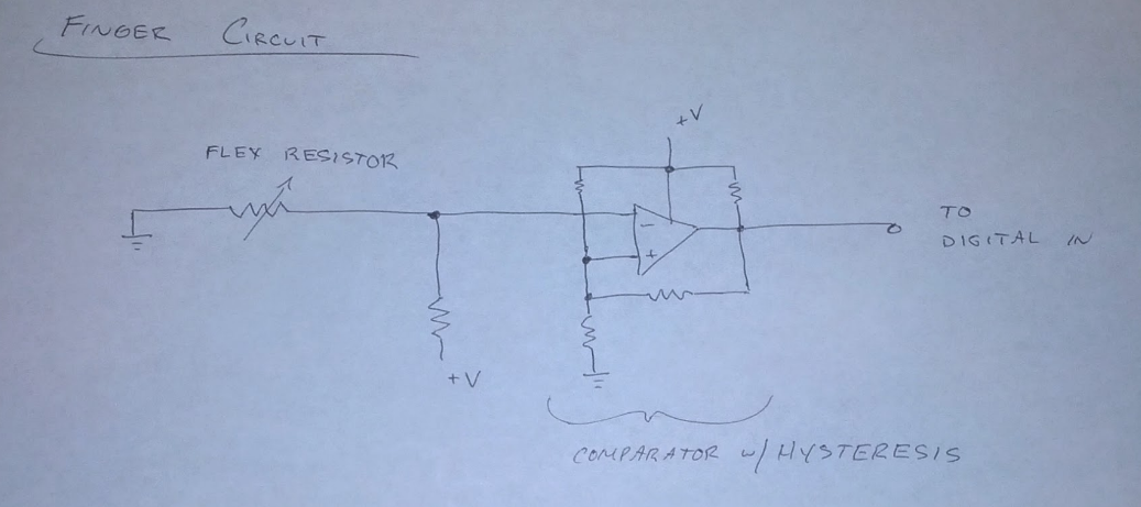
Here is a rough layout of the finger circuit. The finger resistor makes a voltage divider. This voltage is fed into a comparator. The resistors around the comparator define the hysteresis band. This gives us a simple digital out to use later on. Additional circuits such as a Parallel In/ Serial Out Shift Register could be used to tie more than one finger to a given digital pin.
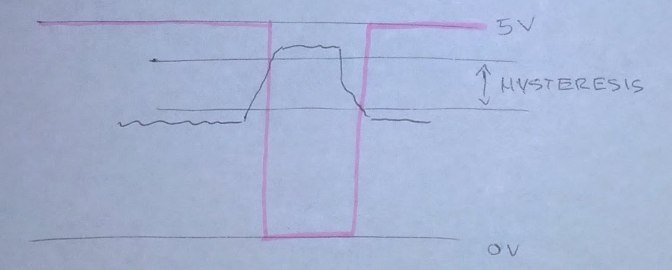
The hysteresis works like this:
If the finger voltage rises above a certain threshold, the pin goes low. In order to go high again, it has to drop further. This creates a kind of dead-zone and avoids oscillations if you have a single switch voltage.
 Eric Jacob

Discussions
Become a Hackaday.io Member
Create an account to leave a comment. Already have an account? Log In.