 Marius Taciuc
I managed to upload the Schematic files (also) for the B1 iteration of my project. Everything is looking so pretty now.
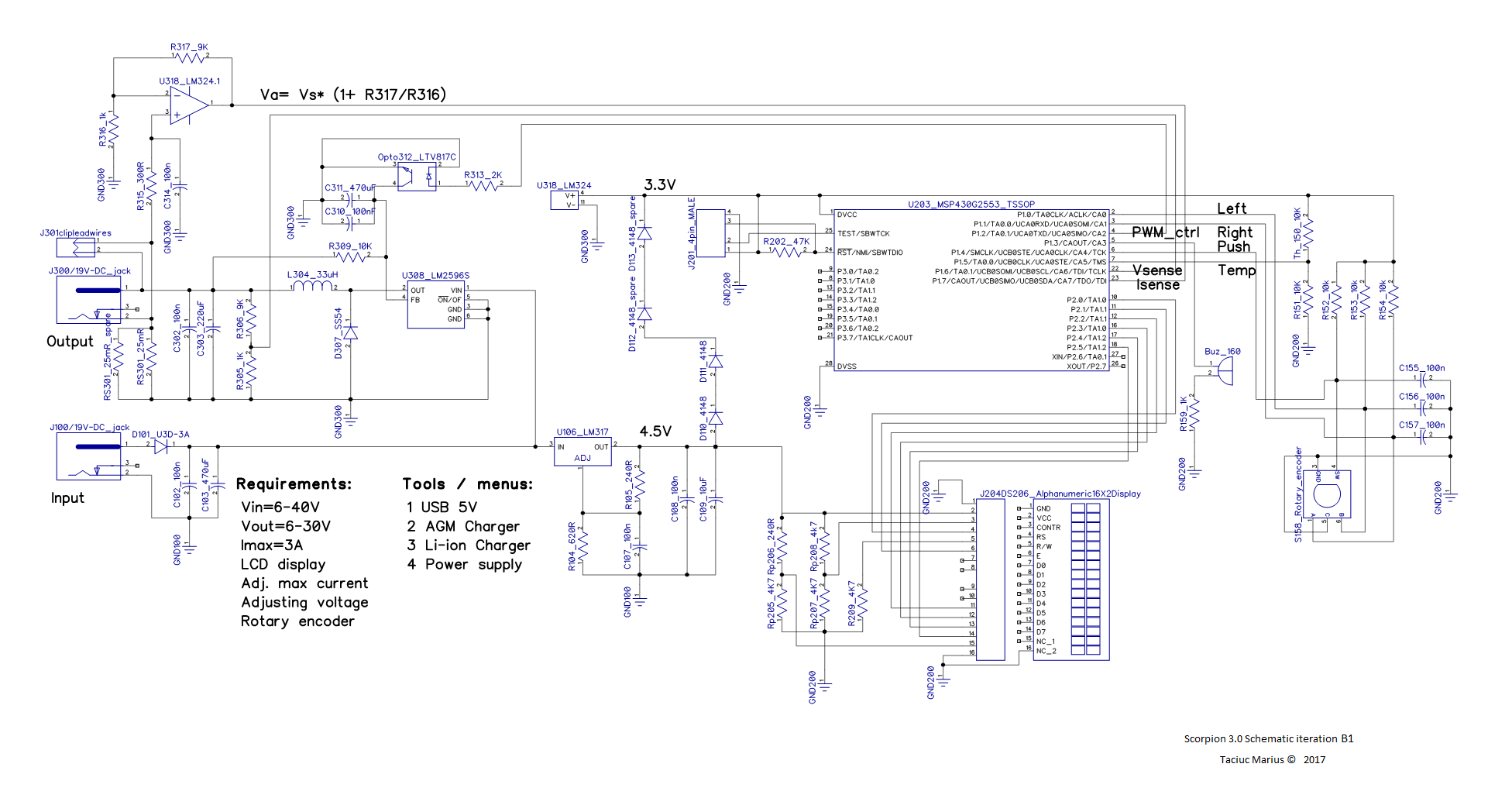
As you can notice, I changed the package of the MSP430. This is what I have recently purchased and I'm gonna go with it. I also replaced the op-amp with the LM324. This one has better accuracy and it promises to add less noise to my reading. I relabeled the names of the components to make the entire design more clear. I updated some component values, re-positioned the rotary encoder and added a buzzer.
I managed to test the control of the LM2596 using a optocoupler instead of a potentiometer and it works just fine. I'm not sure about the resolution it will provide and i'm not sure about the range in which I will be able to adjust the output voltage, but I'm pretty confident that I can make it work, so I'm gonna go for this design. After all, if the resolution of the PWM won't be enough, I could lower the frequency and increase the resolution. (I so have to explain this in a future post)
I think the next step would be to come up with the layout and order some PCB's.
Stay tuned!
Discussions
Become a Hackaday.io Member
Create an account to leave a comment. Already have an account? Log In.