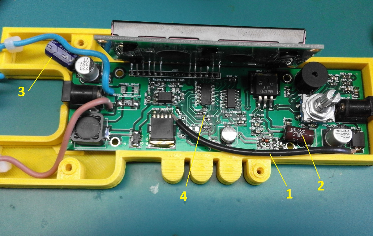
During the testing sessions, when I was increasing the output power above 30W, sometimes the MCU would reset and I was seeing this in a jam of the chars on the display. I realized that I made a mistake in the design of the layout and that would be routing the power trace too close to the MCU and too close to the 3.3V line. When I calculated the voltage per meter for some traces, I was shown values of almost 5000V/m and clearly this is not so good for my EMC.
The HW modiffications I did are the following:

1. Cut the power trace on the bottom side of the PCB and replaced it with an external shielded cable
2. Replaced the output cap of the LM317 with a 470uF one.
3. Doubled the size of the output filter
4. Placed a 100nF cappacitor in parallel and very close to the MCU
Now it works like a charm and with this firmware, I managed to output a maximum power of 45W out of it. The efficiency is very good and the LM2596 does not heat above 40C, which is a success. Normally, a C1 iteration of the layout should be created after the first series of tests. Stay tuned for more updates and hopefully some test report posts.
 Marius Taciuc
Discussions
Become a Hackaday.io Member
Create an account to leave a comment. Already have an account? Log In.