Construction
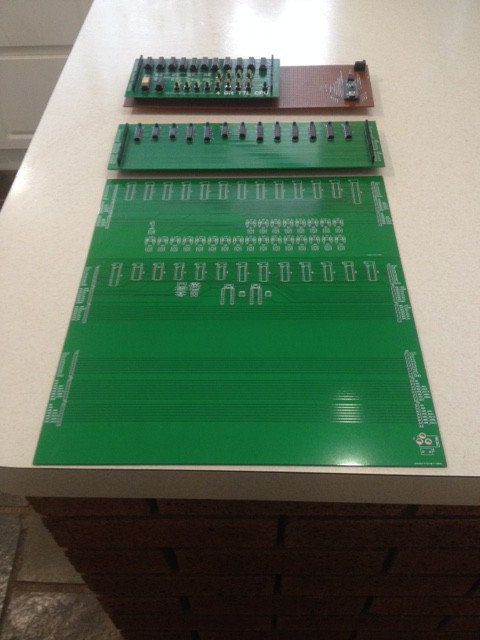
My boards are back. I erred on the side of big for these boards. The Control Board has two piggy back daughter boards. I when big so that the auto router would work. But it was costly (almost double what I paid for my 4 bit CPU on a same same basis:
Okay, the view distorts the relative sizes but you get the idea.
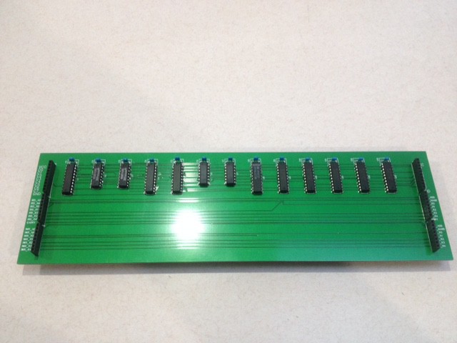
I think I am on the right path but instead on the headers being vertically aligned (as show below) they should be in horizontal rows. Then each daughter board would be long and narrow:
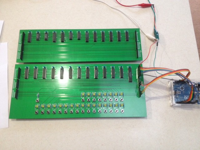
This is the register board, you can see how confident I am, no IC sockets!
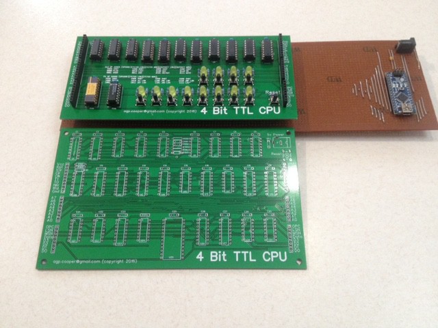
Here is a close up of the 4 bit CPU Front Panel (in the Arduino test-bed) above the main CPU board:
The Front Panel is working but I have yet to write a simulator to test the monitor program (or assemble and test the CPU board).
So other than buying some more component to finish off the other two boards I need to test each board to make sure they are working as expected.
The Wind Is In My Sails
Not often I have this much go right. Both daughter boards work fully. The only error on the boards a label I wrote "!WR_ADD" and "!WR_NAND" instead of "!WR_ALU_A" and !WR_ALU_B".
Magic!
The Control Board has one fault (so far). I have offset the Front Panel Board (i.e. I/O/Memory board) header pins about 1/2" too far down. It is cosmetic.
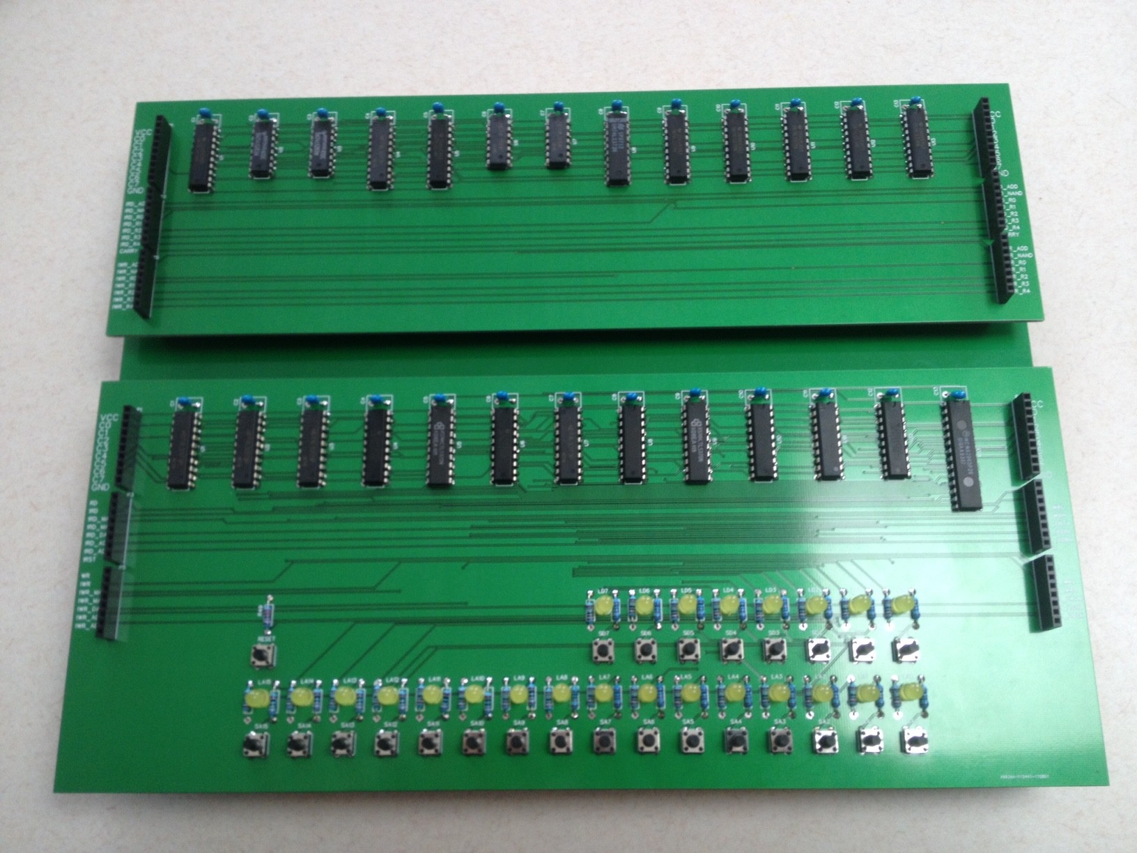
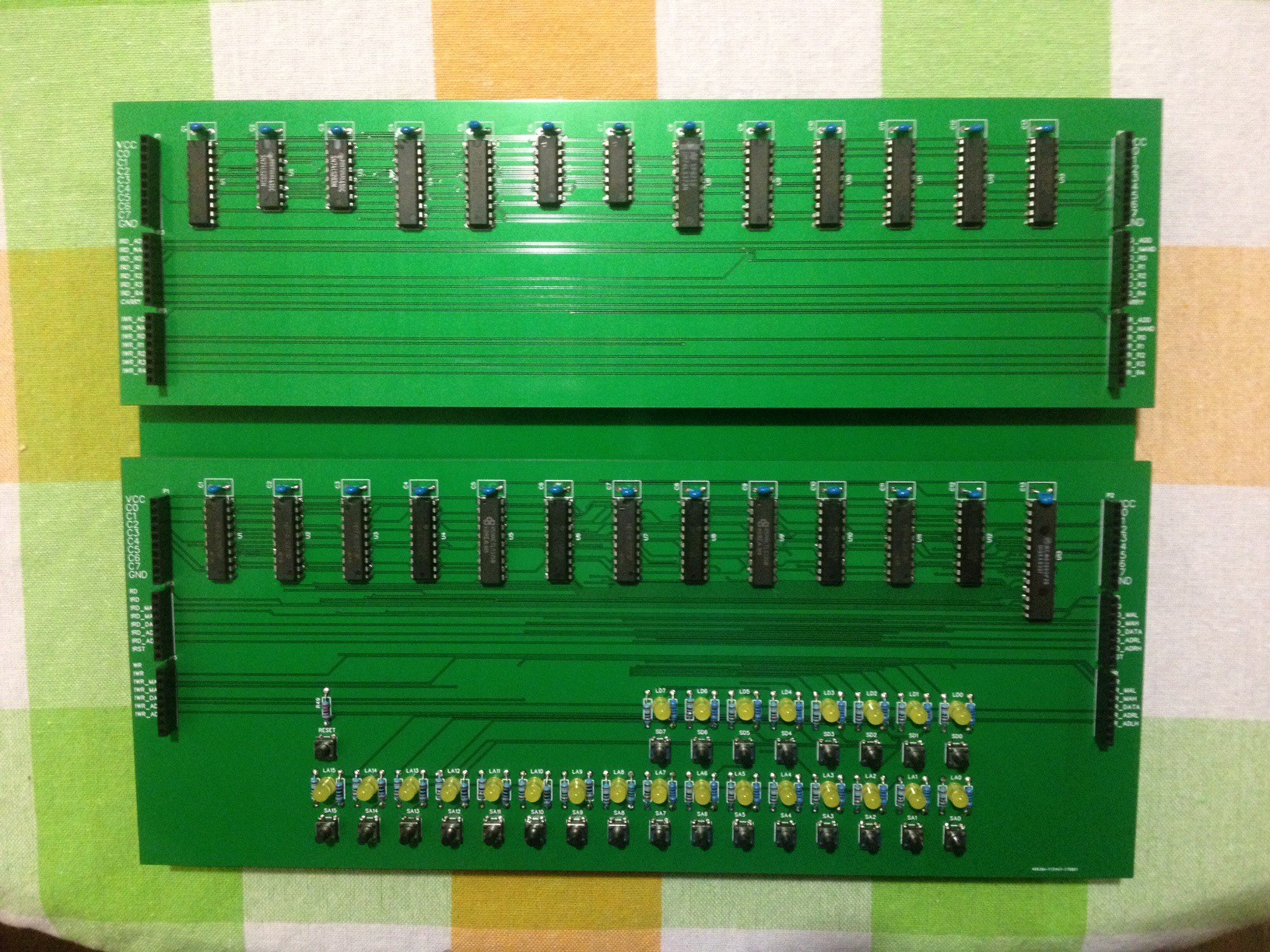
Here are the two completed boards (and the Arduino I used to test the boards):
Stop
I assembled the clock this morning on the Control board. Power up but no signal. Actually the scope said negative. Powered down and checked the ICs to see if they were hot. On was warm. Now I have done this before - hooked up the power jack the wrong way in EasyEDA. It happens when EasyEDA change their component library and I have to fine new components, it causes all sorts of problems. But this is partially my fault as I hooked it up wrong.
Pulled the power jack, cut off the middle tab and refitted it in reverse. Powered up, now I have a clock signal but it has sub-harmonic digital noise. I am using an unusual clock circuit in that I use schmitt triggers instead of simple gates. The bread-boarded version of this circuit works fine so I assume the 74LS132 is damaged (pretty likely).
Here are the boards after I stopped working on i:
And a trial fit:
Note the gap between the daughter boards.
There are enough errors in the Control board that I will update the PCB and get it remade.
Review
I was not that happy with the diagnosis for the clock so I had another look.
First I did not have any 2.2k resistors so I used 2.7k resistors. An easy check would to replace them with 1.8k resistors. The 2.2k resistors were on the high end for LS-TTL based on my research. I got a big improvement but still some weird clocking with extra cycles (sub-harmonics). So I dropped the resistors to 1k by paralleling the 1.8k resistors with the old 2.7k resistors. All good!
Pulled to resistors and replaced them with 1k resistors, but no:
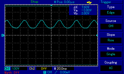
I cleaned up the PCB and checked for shorts. The resistor pad was damaged and shorting to ground. Unsoldering plate through holes is a real problem with low cost PCBs. Bridged the damage, but the output was bad:
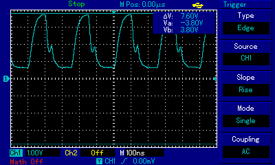
Also note that the waveform floor is about 0.5 volt (too high). In the beginning the floor was lower and the mini-hill higher, after a while the waveform settle to this:

Note how high the floor is (nearly 1v), clearly the short damaged the output drive and I was watching output drive fail.
The Control Board
Other than some ringing on the clock signal (which does not seem to upset things), the PC is happily counting away and the reset works. Although the rest of the circuit in not complicated I cannot test it. The clock is too fast for the Arduino. Originally I was going to have a jumper on the crystal so I could inject a low frequency for test purposes. It never happened. Now I have to test it via the ROM!
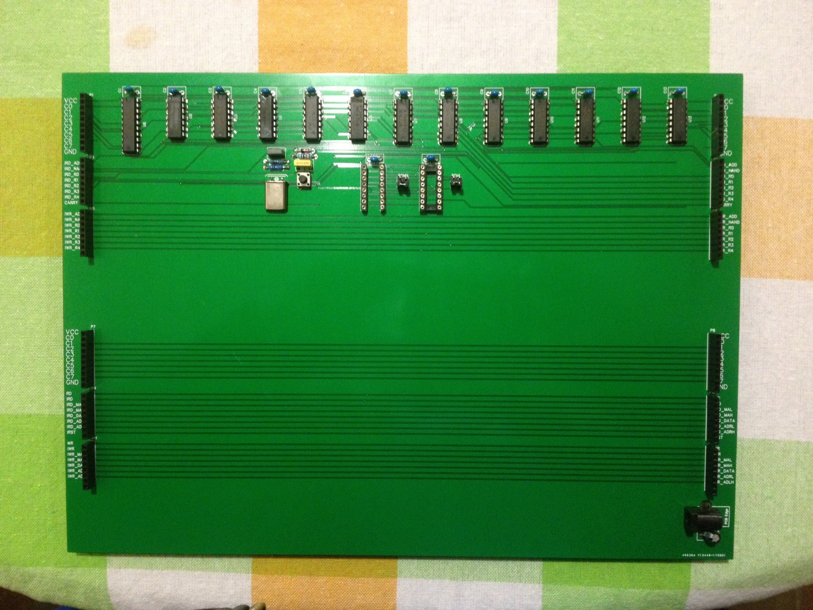
The controller board:
The assembled CPU less PROM:
AlanX
 agp.cooper

Discussions
Become a Hackaday.io Member
Create an account to leave a comment. Already have an account? Log In.