AnsonAnson
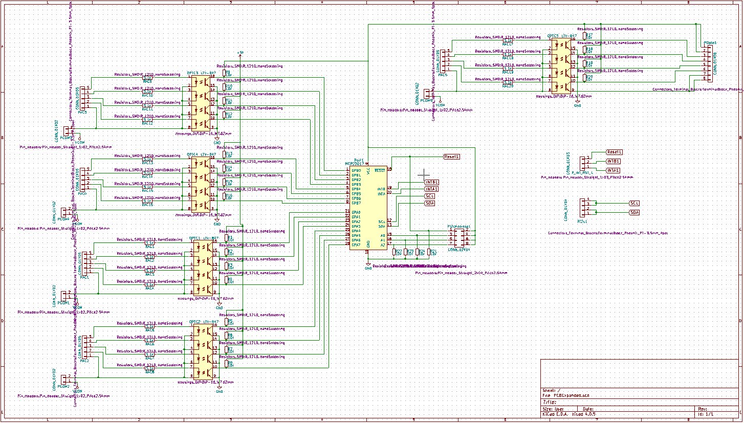
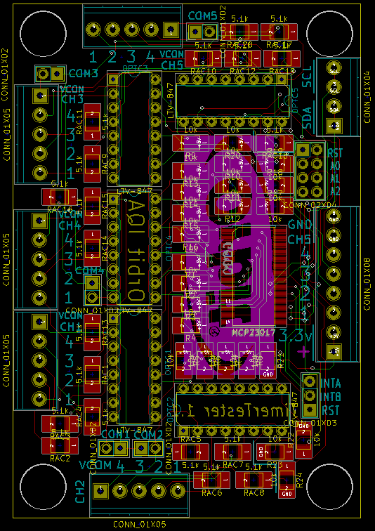
PCB Schematic and PCB layout in KiCad. BOM is attached.
PCB box 3D print on my Thingiverse:
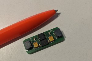
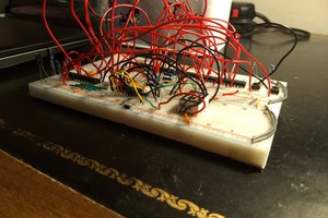
This PCB monitors irrigation controller 24vac outputs. It uses LTV-844 optocouplers and an MCP23017 port expander to output status over i2c
Already have an account? Log in.
To make the experience fit your profile, pick a username and tell us what interests you.
PCB Schematic and PCB layout in KiCad. BOM is attached.
PCB box 3D print on my Thingiverse:
PCBExpanded.zipKiCad filesx-zip-compressed - 801.93 kB - 08/01/2017 at 20:54 |
|
|
BOM.xlsxBOM from Mousersheet - 12.65 kB - 08/01/2017 at 20:54 |
|
1.1 Raspberry Pi 3
A standard Raspberry Pi 3 is used as the data processor, data logger, webserver to host the data, and interface. Setting up and running the Pi will require:
1.2 Timer logging PCB
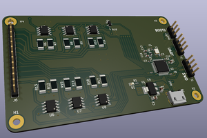
A PCB should be fabricated (recommend OSHPark) and the components soldered on.
1.3 Timer Logging PCB case
It’s recommended but not necessary to use a case for the PCB. Below are some recommended print parameters:
Originals were printed on a Lulzbot Taz6 with a .4mm nozzle and sliced with Cura:
1.4 Misc. Wires or CAT6 cabling, screwdriver, wire stripper/knife.
2.1 Raspbian with latest updates
2.2 Apache2 with PHP
2.3 Webserver Scripts
After setting up webserver as described in the Software section, boot up the Raspberry Pi, connect to Externet, and confirm that the IP address brings you to the Orbit QE test homepage.
 George Ebeid
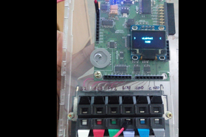
 Jithin