 Terje Io
A new prototype has been made:
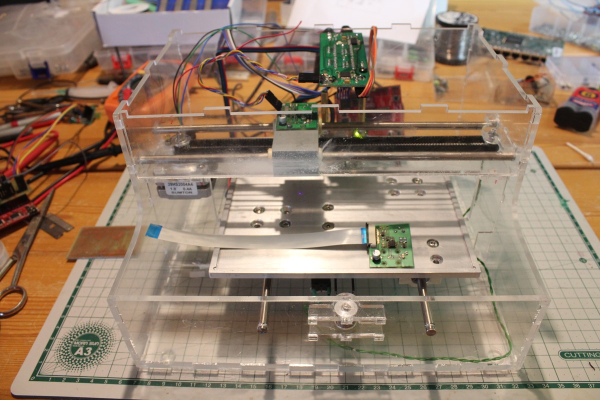
This is a lot stiffer than the first, this setup has the custom controller connected to the LaunchPad version of the diode driver. The PCB on the table is the driver that will be used finally, connected to the controller via a flat cable.
Calibration is vital for good results, I started with coarse adjustment of laser focus. A wax based shopping receipt (the ones used in thermal printers) can be used, the laser light will blacken these when in focus.
Next step is backlash compensation, the original machine has 9 pixels of compensation so I started with that. Remember one pixel is about 20 micrometers at 1200 dpi:
9 pixels
11 pixels
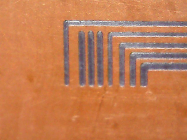
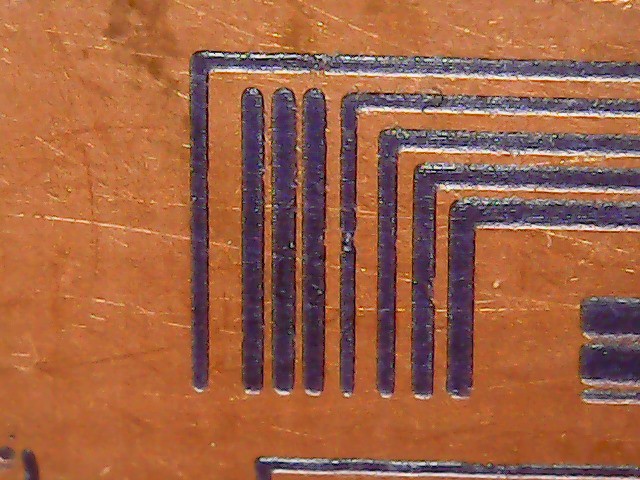
13 pixels, the best one but the 0.1mm line is a bit wider in the horizontal direction than vertical, I suspect focus needs adjustment.
15 pixels. Perhaps I need to test for 12 as well - but focus first:
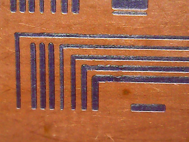
A quarter turn of the lens in the direction I suspected I needed to go.
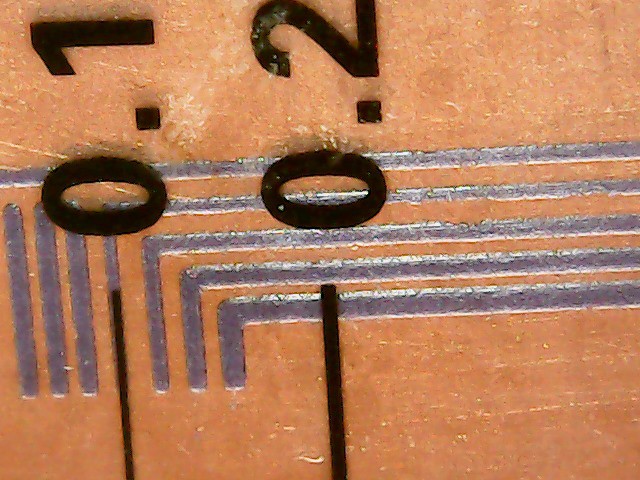
A quarter turn more, I think I'll stop here - beeing able to print at 0.1mm (or less) resolution (4mil) is good enough?
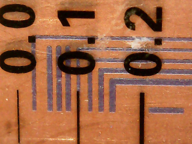
For me this means the project is a viable solution to making PCBs for down to 0.5mm pitch components, maybe even less. Presensitized boards is a must when aiming for less than 0.25mm (10mil) trace widths, dust will surely be a problem when using film.
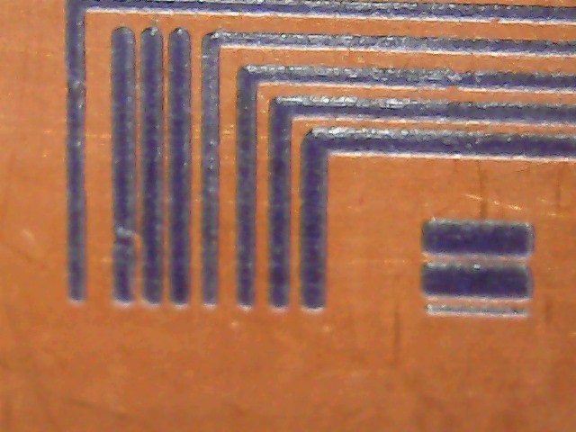
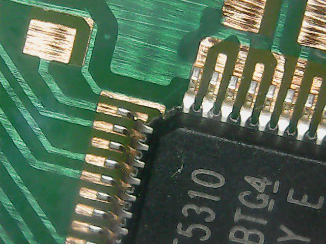
Finally, a shot of a corner of the MCU on the controller board - made with the original exposer (0.5mm pitch):
Discussions
Become a Hackaday.io Member
Create an account to leave a comment. Already have an account? Log In.