This project used Adafruit wave shield, Sonic range sensor, two motor controllers (IBT-2 and IMS-2 more on this later), LEDs, two micro switches. My plan was to test each of these separately, I've worked with all of them in the past (except the IMS-2 motor controller), but wanted to refresh my memory.
The plan was to have a master Arduino then have it control the Arduino with the Wave shield. Their are limited pin's available with the Wave Shield.
I build a Wave Shied in the past and planned on using it. I couldn't get the Wave shield working again. I suspect the problem was acidic solder flux, next time I will clean the flux off after finishing a project. I ordered a new one and with the speaker.
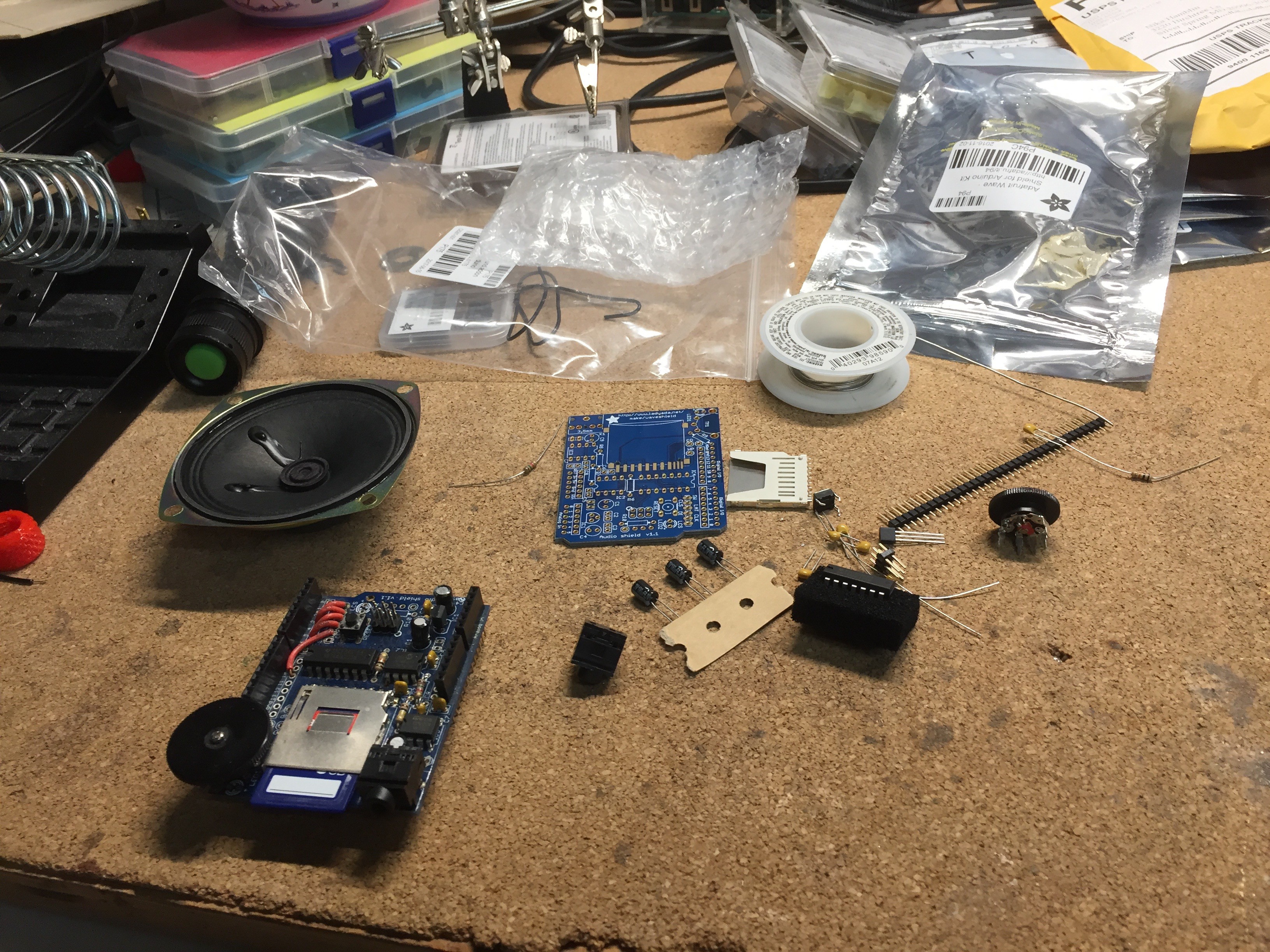
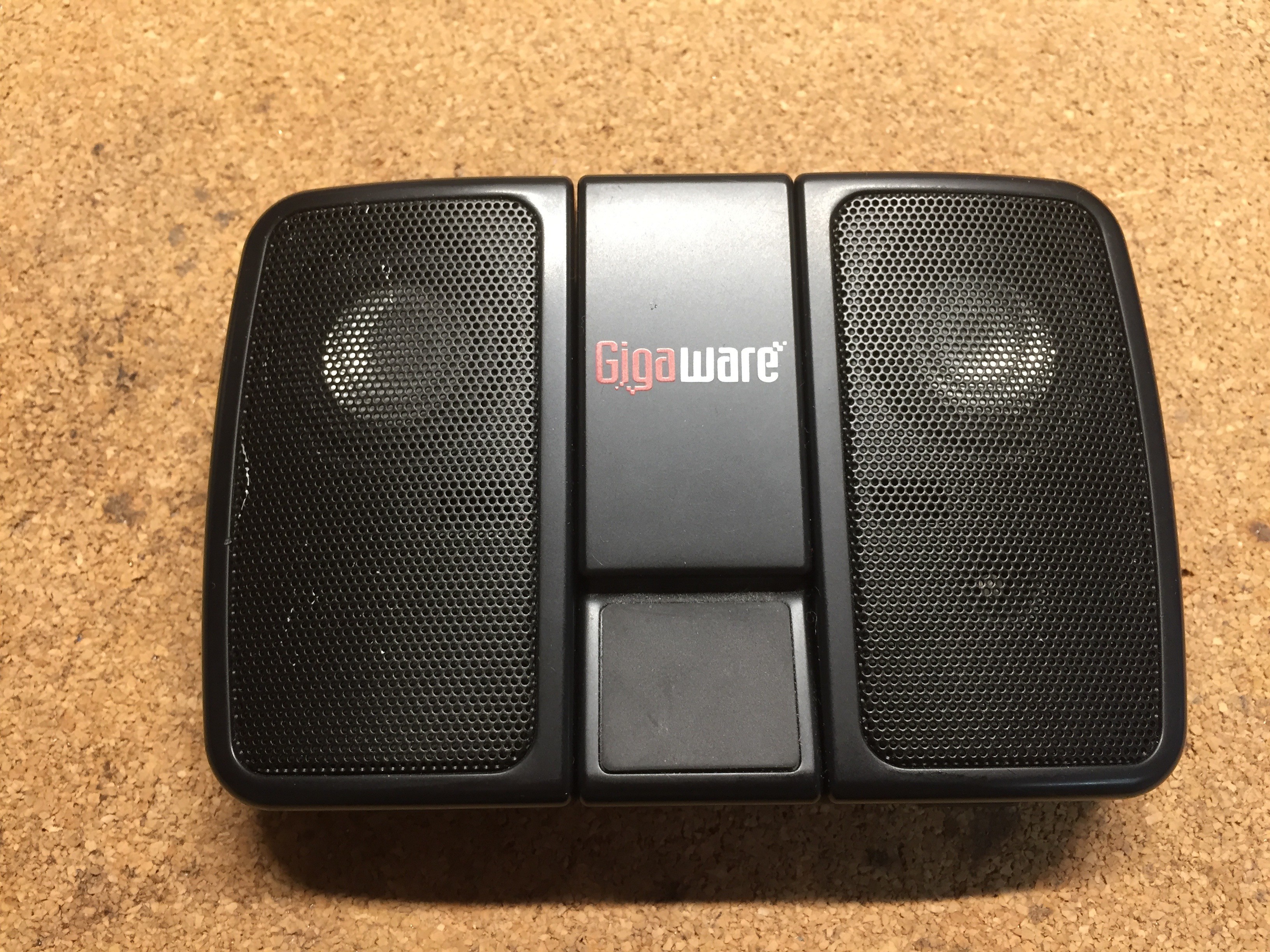
Then I purchased the Captain Underpants theme song to the movie, I also found the audio of a toilet flushing. I converted these so they would run on the Arduino. I also soldered wires for the speaker to the shield. When I tested this arrangement I was not happy with the speaker it was not very loud. I had a cheap portable speaker that I tested and the sound was much better, louder.
I then wanted to test being able to trigger the Wave Shield from the master Arduino. My plan was to simple set a Pin high. First I connected a micro switch to the wave shield arduino to use that to trigger it. I connected the switch to pin 12. Immediately had problems when the wave shield started up. After posting a question on the Adafruit forum, I got a quick answer. Pin 12 is a reserved pin used to read the memory card. I then read the spec sheet (like I should have from the start), I then used 8 to trigger. This test worked after this change. Then I went to trigger it from the master arduino. I spent an Saturday afternoon trying to get this to work unsuccessfully. I took a break came back and looked at it Sunday and released that I had not setup up a common ground between the two arduino's. Once I setup common ground the test worked.
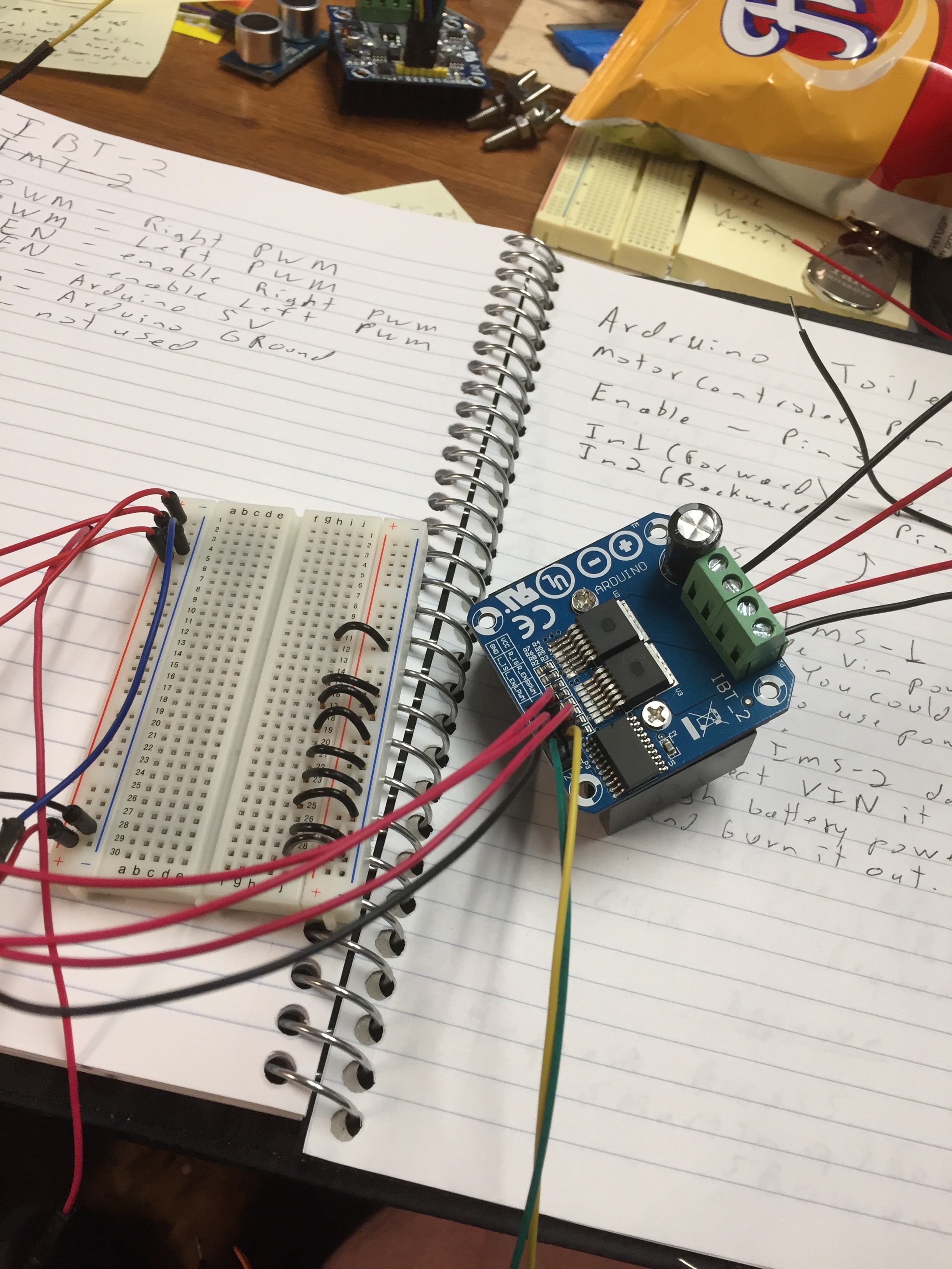
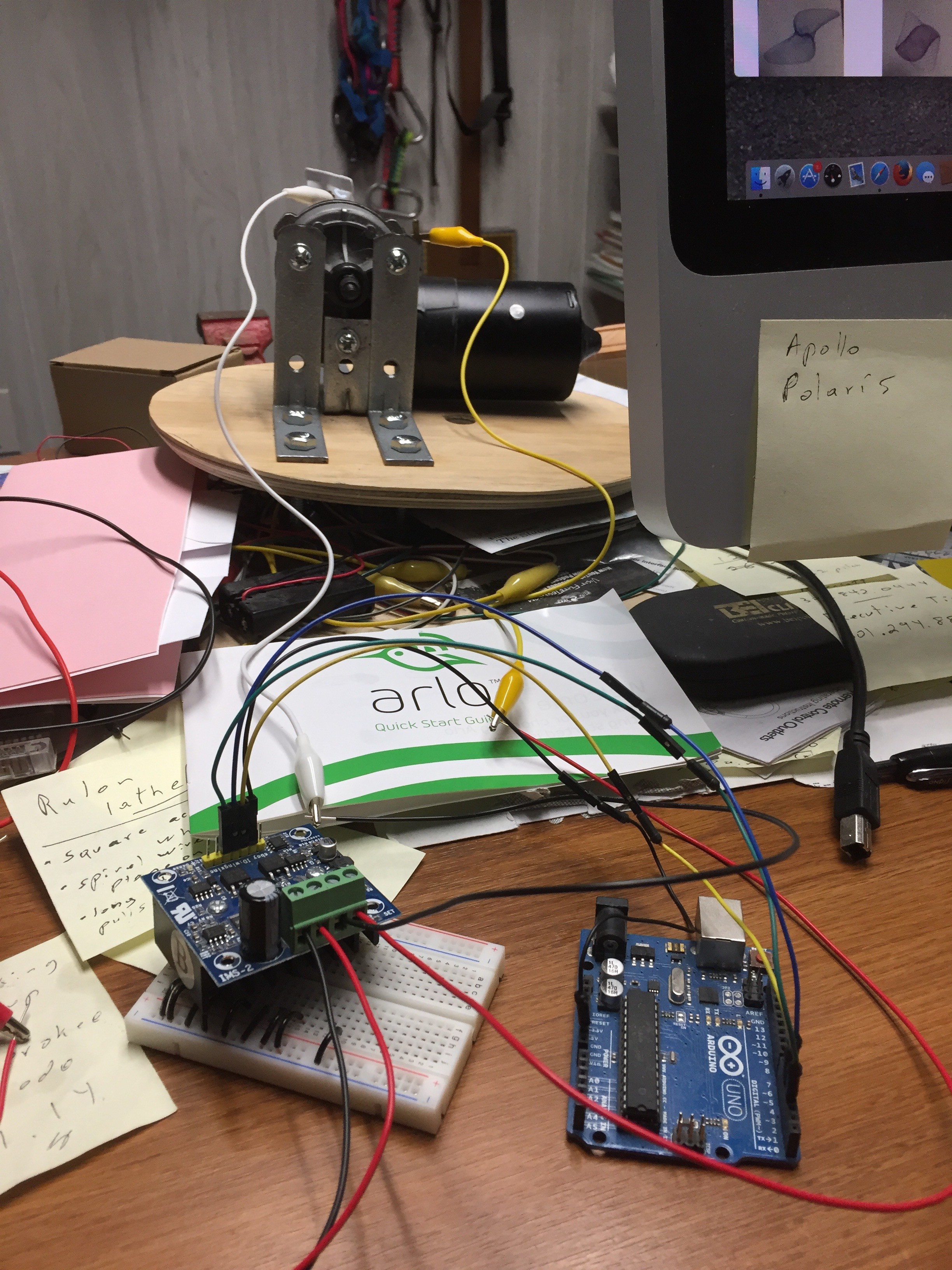
Testing the IBT-2 motor controller was very easy and worked first time. The IMS-2 (I have the C version) was a different story. I could find very little documentation on this, everything I found was for the IMS-1. I followed the documentation for the IMS-1 setup, the test didn't work. It was right after this I released the Arduino was bricked. What I discovered is that the IMS-2 gets power from the high side automatically, when you put power to the high side you will see a LED light up on the motor controller. The IMS-1 (and IBT-2) both get power from the low side. The solution was simple do NOT connect the power to the VIN pin on the IMS-2 from the arduino. From now on I'm going to use the IBT-2 motor controller, it is very well documented.
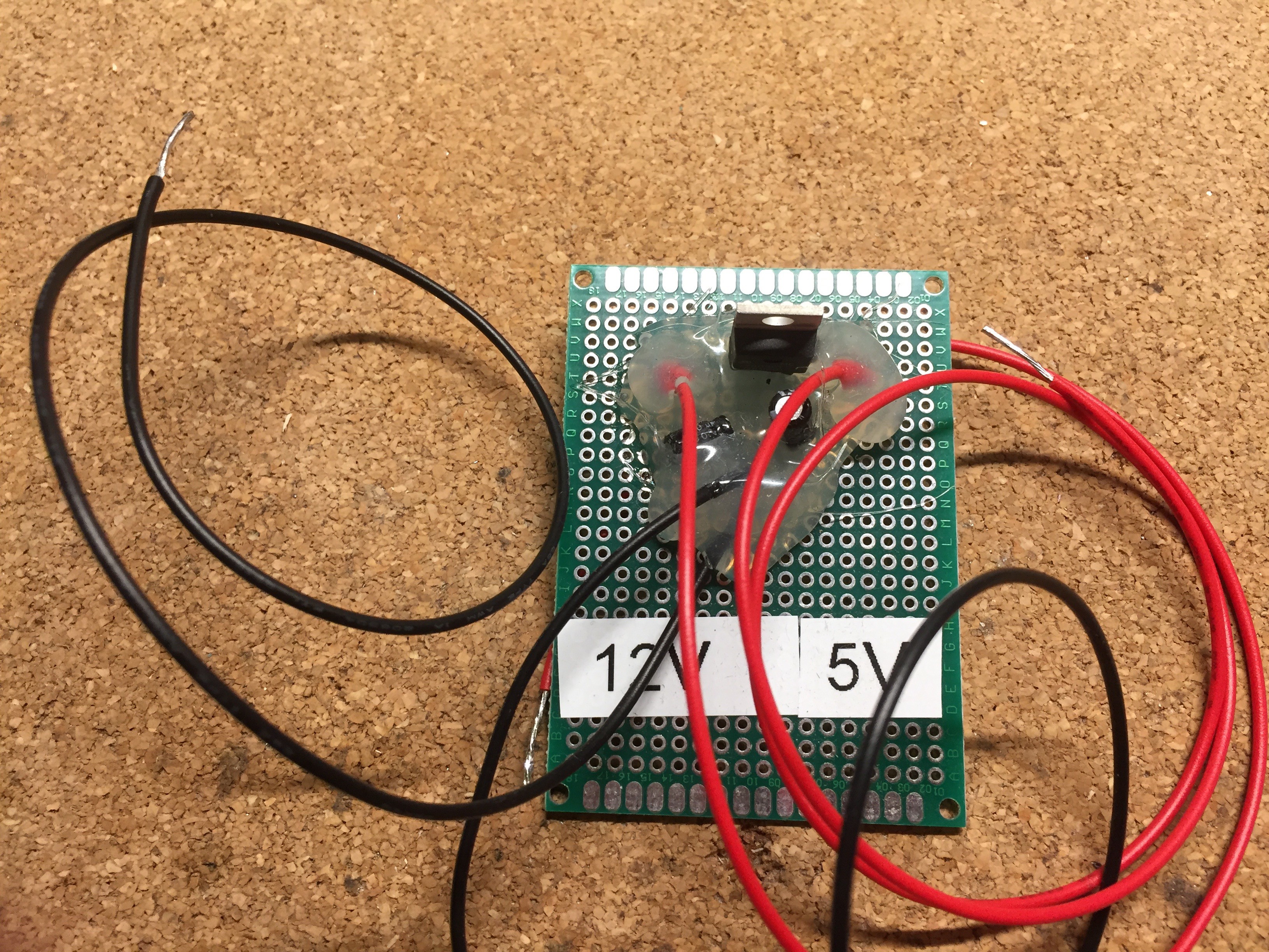
Lastly I need to work out the details of my power. I planned on run two 12v motor cycle batteries connected in Parallel. I also needed 5v power. I used a LM-7805-CT Linear Regulator and two micro capacitors on either side. This worked about extremely well, so well that I built a second one to use for another project.
Discussions
Become a Hackaday.io Member
Create an account to leave a comment. Already have an account? Log In.