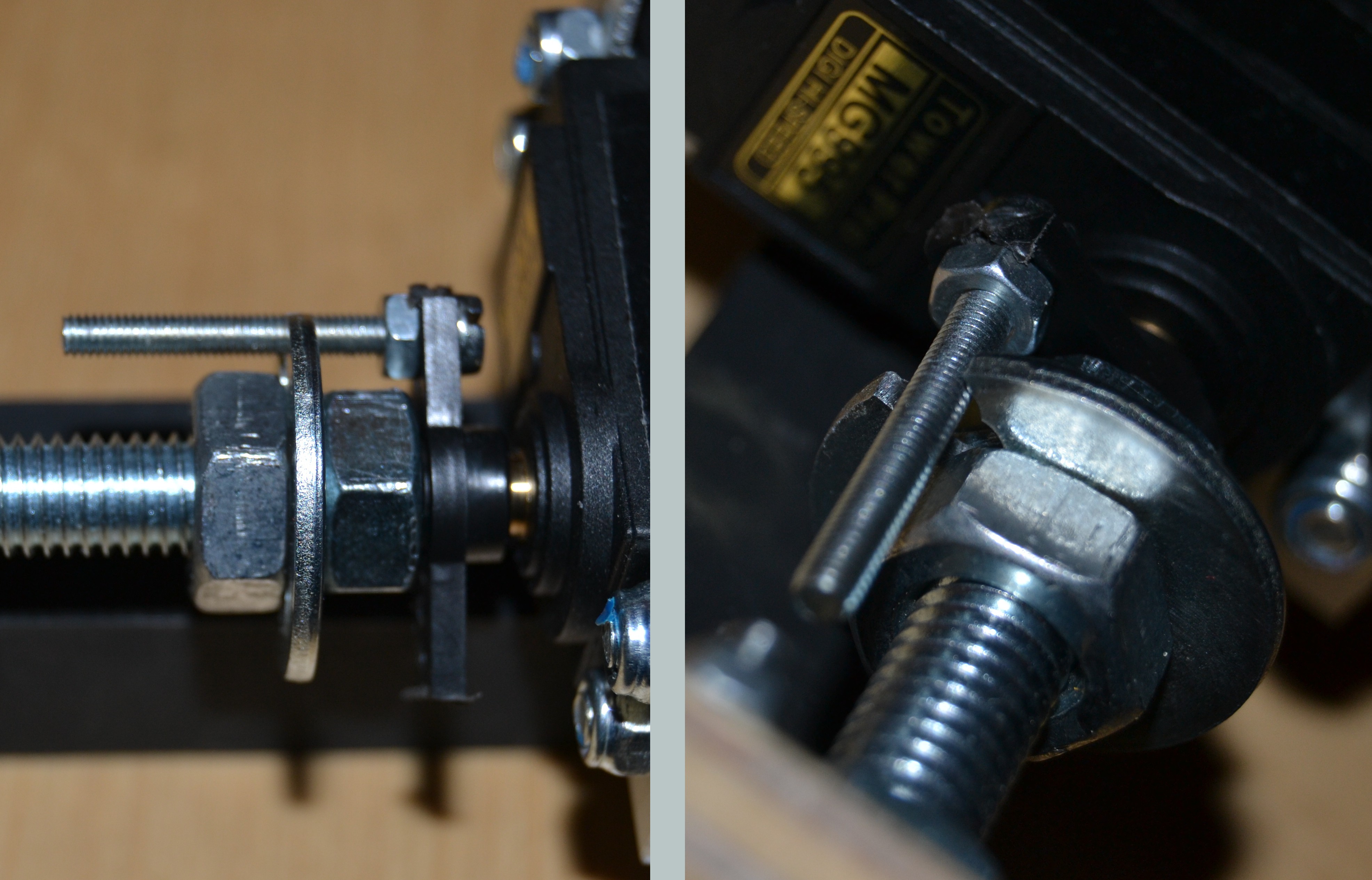
As seen on other CNC projects, the coupling between rod and motor poses a serious problem, based upon accuracy in making. I encountered the same on the first Axis (Z). Therefore for the X and Y Axis, I used a different Approach with a simple non-fixed coupling, you can see here:
By communication with some really clever guy working on DIY CNCs, I learned that "fixed" connection made by M8 nuts tend to wiggle anyway as the construct is not perfectly axis-aligned. He also encouraged me to try out the above. Thanks a lot to Norbert Heinz! Most impressive Video here (german version).
You can see the first test here:
This assembly is relatively easy carried out and does not sacrifice too much precision. It's a great step!
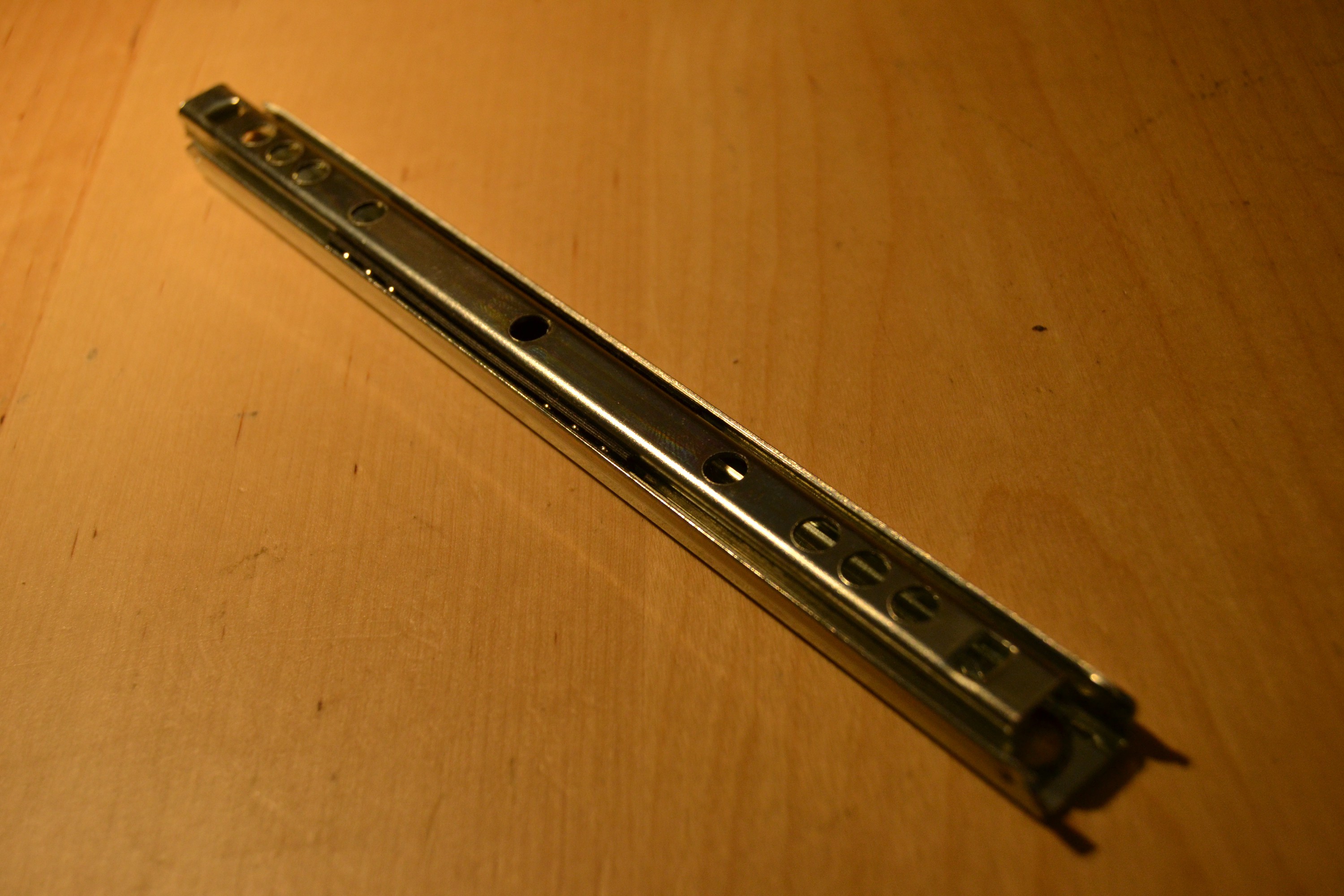
Another important decision is the use of 18cm linear ball bearings, used for drawers from the harware store. It costs about 7EUR for a pair, hence 21 EUR for all 3 axis:
The quality varies by the price, you can get some with higher precision for more money of course. At the moment, I consider the cheap ones good enough. The main reason for this decision is, you save a lot of time making plus you save a lot of space in the machine. The central slider rolls upon 12 balls, of wich 6 can be seen in the photo. They each can withstand 10 Kg minimum and the precision is acceptable.
Regards
 Horst Schlawutzke

Discussions
Become a Hackaday.io Member
Create an account to leave a comment. Already have an account? Log In.