Below a few photo's of the construction of Art 5 and 6. There is one big axle. The small orange gears and Pulleys are (going to be) connected with a screw. They will freely rotate on the Axle and are driven by two motors.
The middle part with the ring contains a nut on which the Art 6 Axle with the big orange gear is mounted.
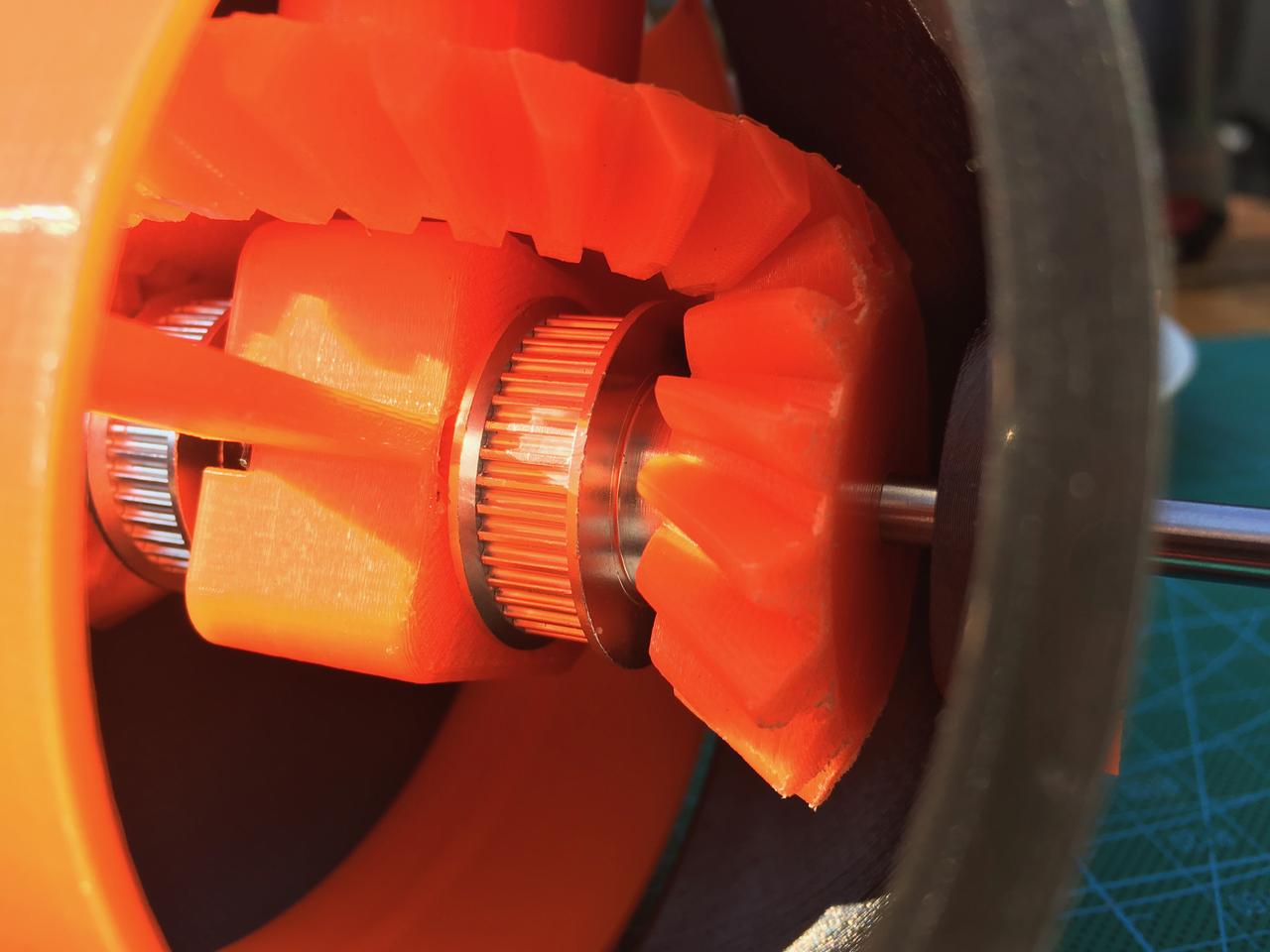
If both the left and right small orange gear are rotating in the same direction then Art 6 is going up or down. If the small gear are rotating in the opposite direction then Art 6 is rotating.
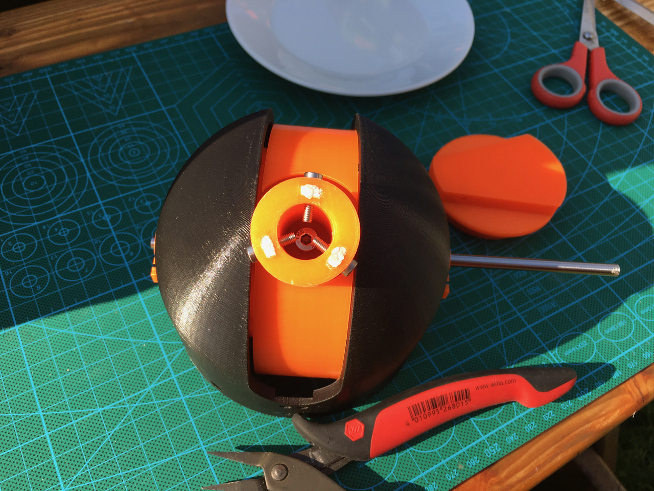
But I don't really understand how it has to be mounted. The hole in small orange gear is much bigger then the GT2 pulley. There is also to much room on the Axle. The small gears are supposed to rotate freely on the axle but the aren't any spacers to prevent them to go up or down the axle.
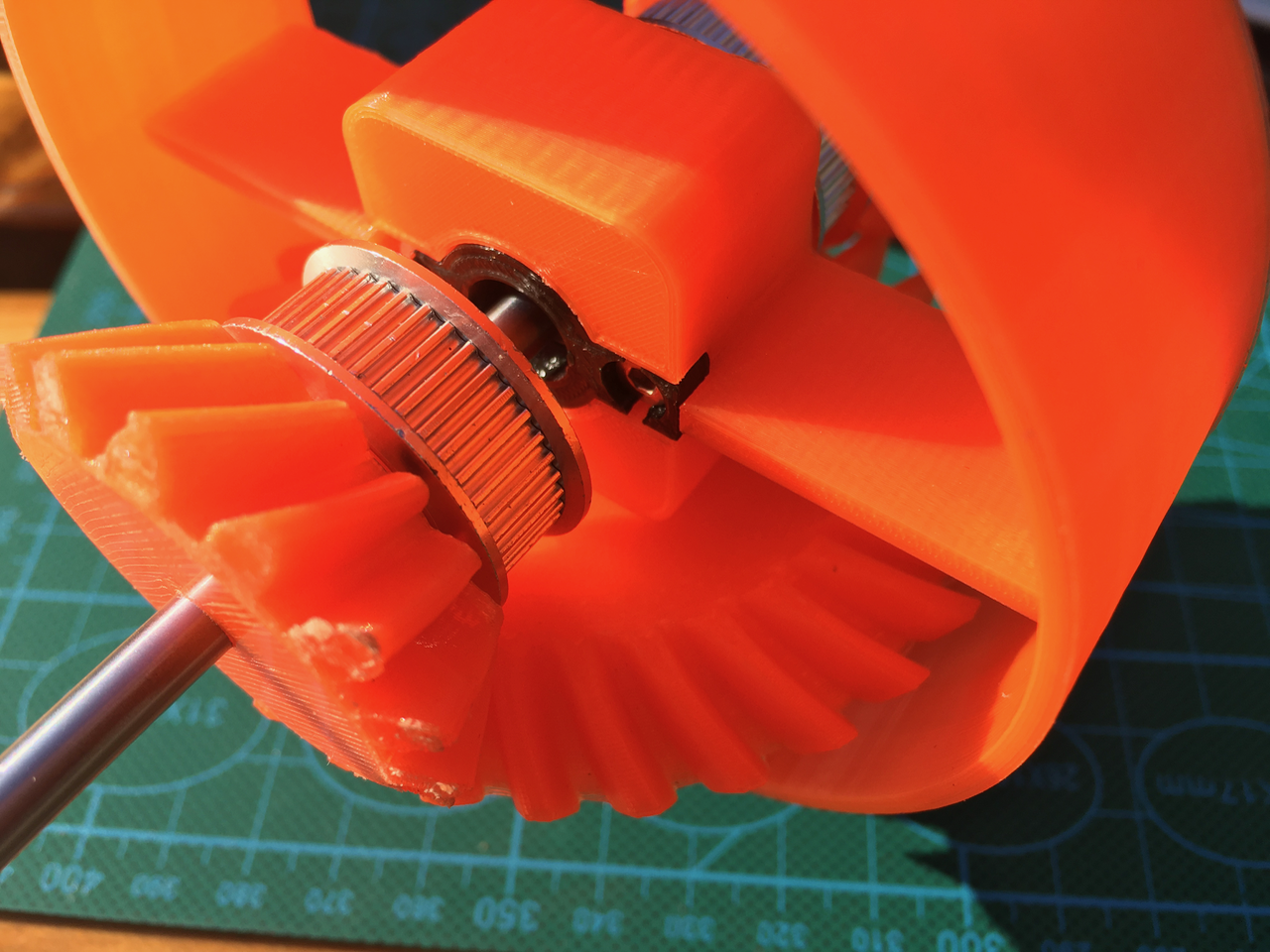
There is a nut in de orange part with the axle. A screw is used to hold the big gear of Axle 6 on top of the small gears. But there are no bearings inside Axis6. And if it rotates the screw becomes looser.
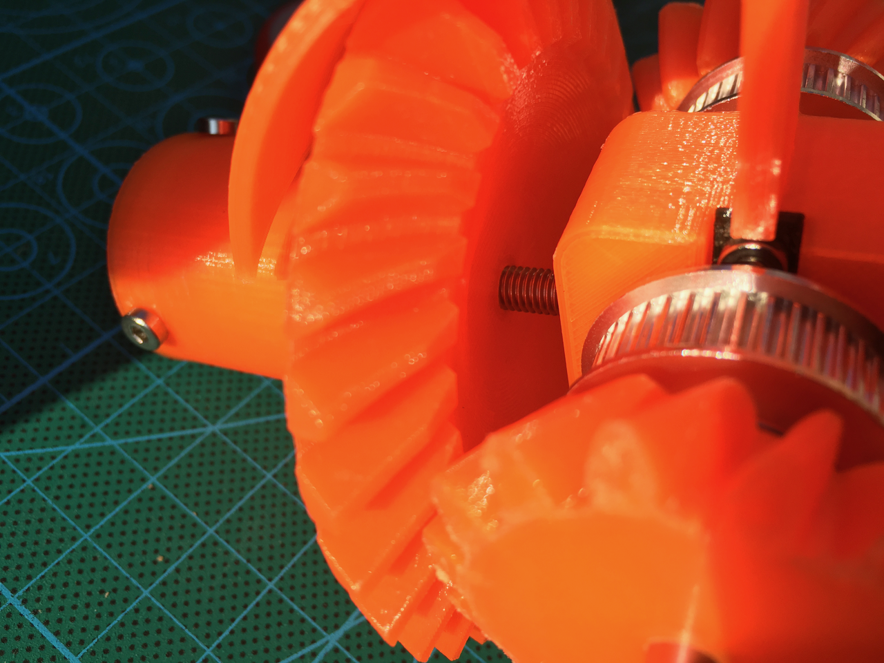
If all parts can rotate and stay into the right place then it will work. So I might redesign this.
Below a few photo's of the idea I have. I have added a piece of black tape on the Axle 6. I want to cut it on the left side of the tape. Then I have 2 parts. One part with the big gear and one part with the shaft.
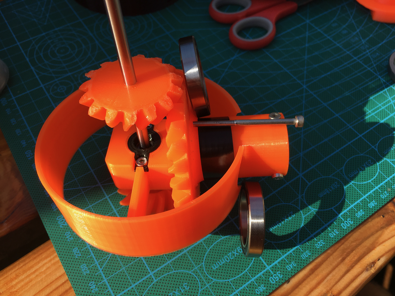
This way I can redesign the "big ring" part and add two bearings (the bearings shown are to big). The shaft is thick enough to use 3 3mm screws to fix both parts together. This way it can still be mounted together and the shaft is fixed between two bearings. (I might even be able to keep the shaft hollow to guide some wires)
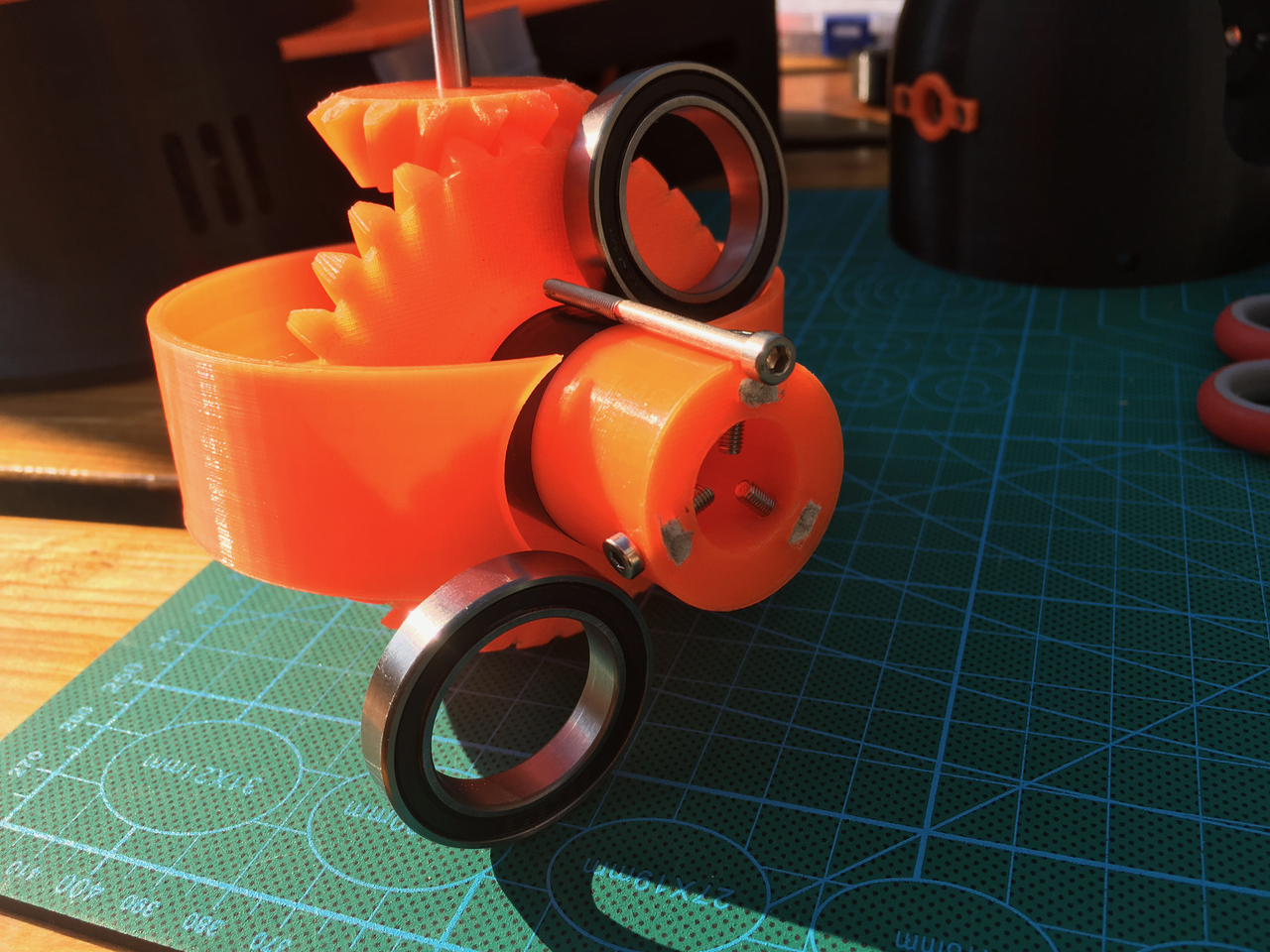
I am also going to redesign the two small gears so the pulley will fit tightly. Small ball bearings will be added to the small gears.
 Sepio
Sepio
Discussions
Become a Hackaday.io Member
Create an account to leave a comment. Already have an account? Log In.
I never managed to assemble this correctly. So I am looking with great curiosity how you do this :-)
Are you sure? yes | no