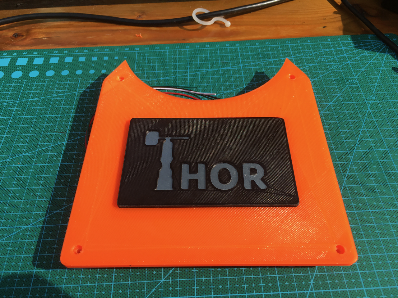
Sepio
Sepio-
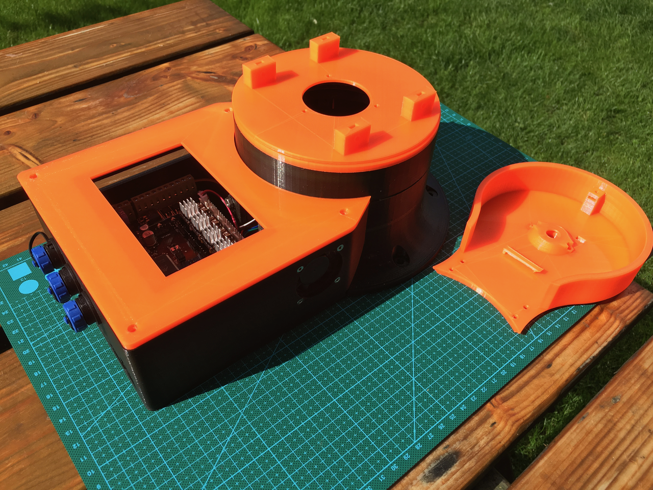
Day 12: Axle Holder
09/03/2017 at 09:46 • 5 commentsIn my previous blog I told about the weak construction of the Axle between Art1body and Art2BodyB. I also had to find a way to fix the Axle in Art1 because of the rotation sensors in Art2BodyB.
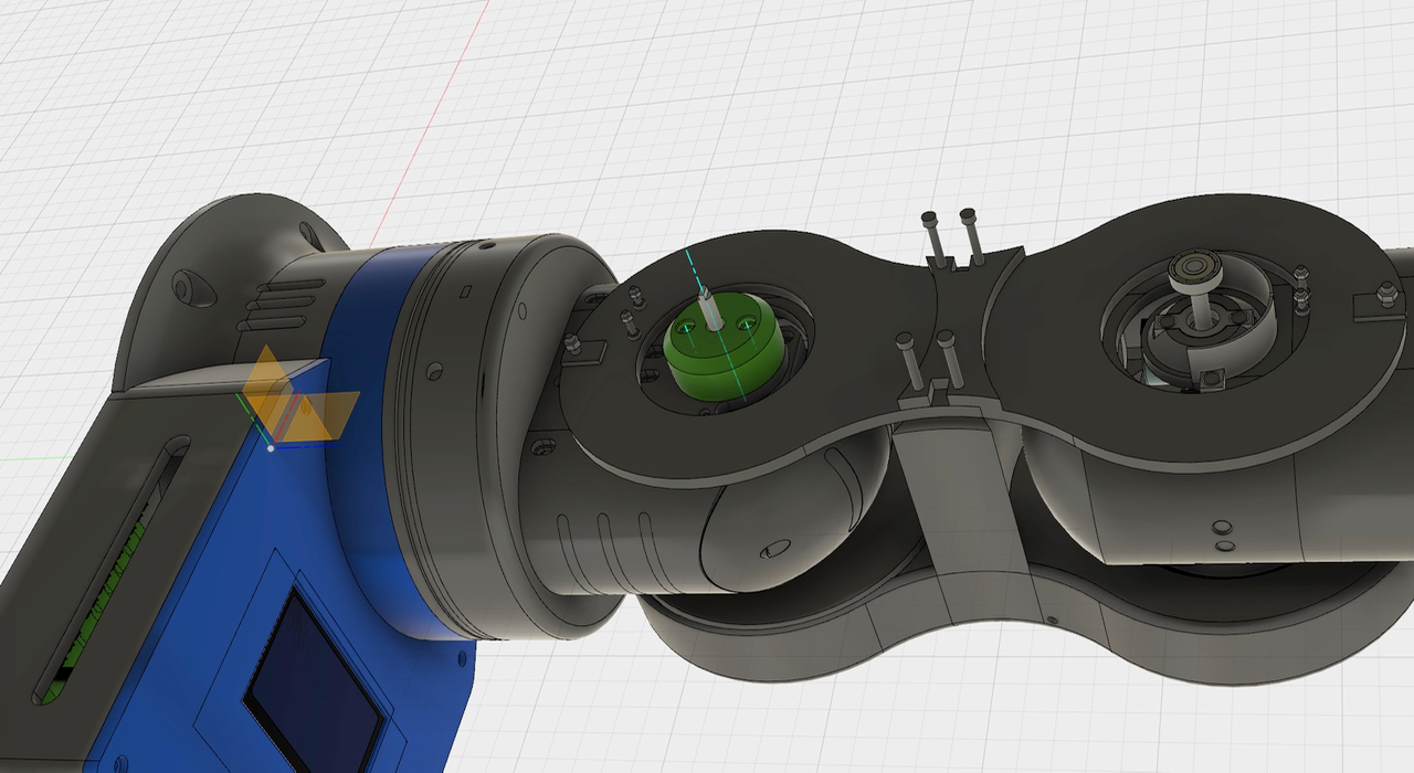
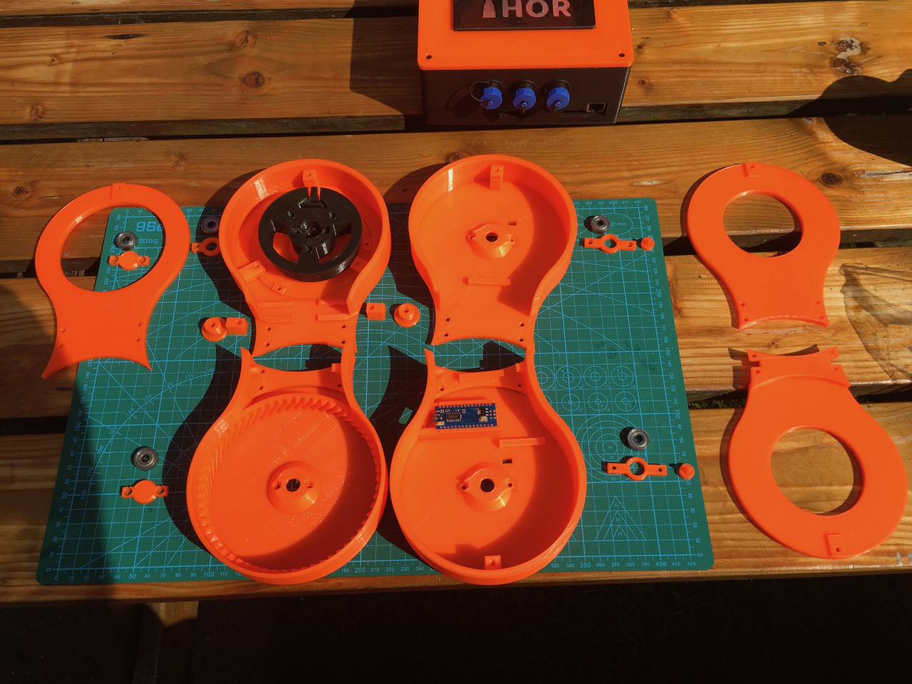
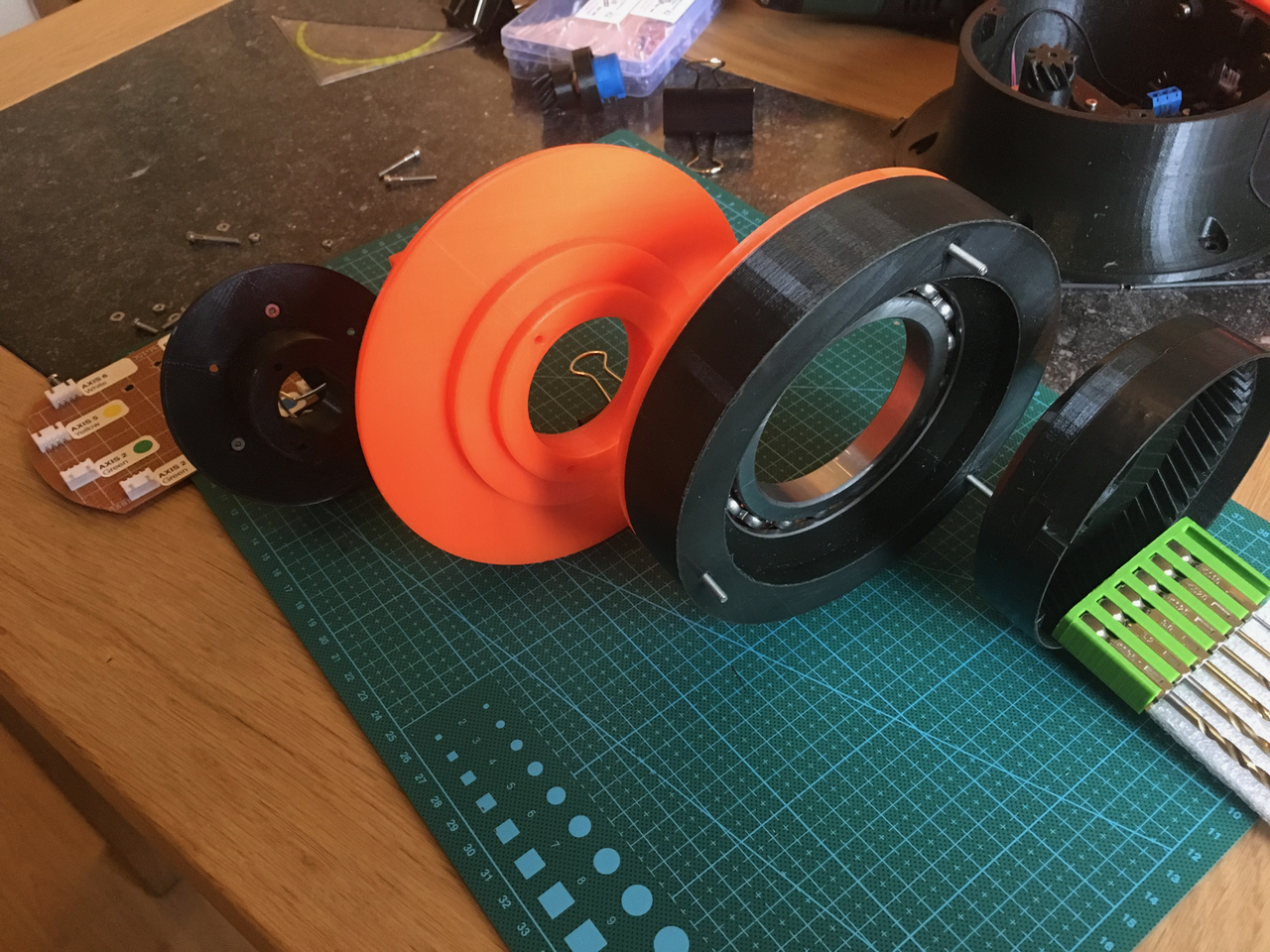
So I decided to design a custom part. The green AxleHolder part in the photo below is the solution for both problems. It replaces the bearing and the bearing ring holder. The same Axle holder can be used for the axle on the right side. (Note: There isn't room for the Art23OptoDisk anymore. Danny's design doesn't need one).
![]()
The new parts and the place it will fit on.
![]()
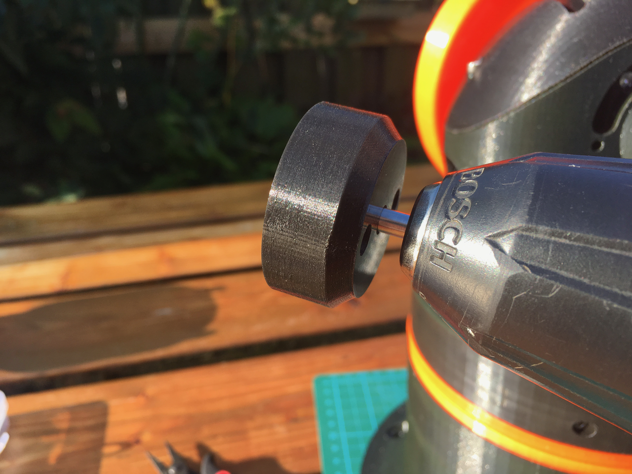
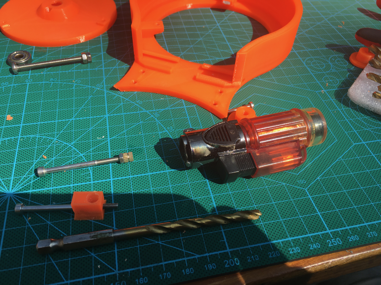
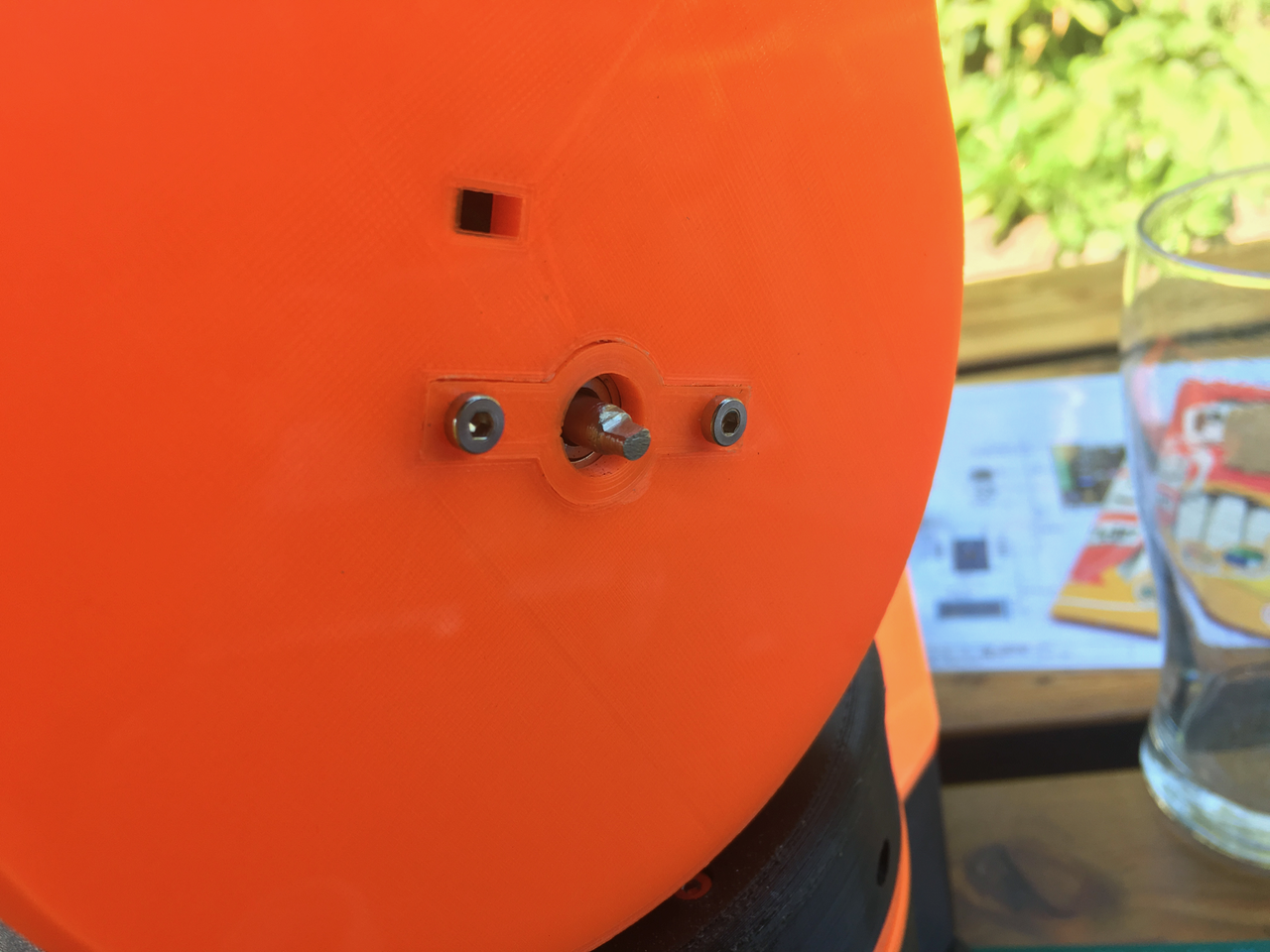
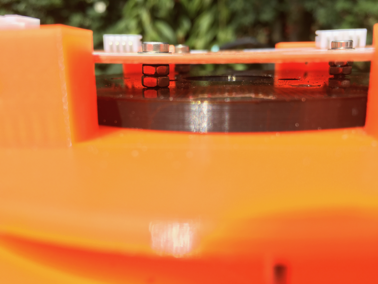
The hole for the Axle is very tight. I did put the Axle in a electrical screwdriver and used it to "screw" it into it's place. Because of the friction the plastic melts a little bit and that keeps the Axle in it's place.
![]()
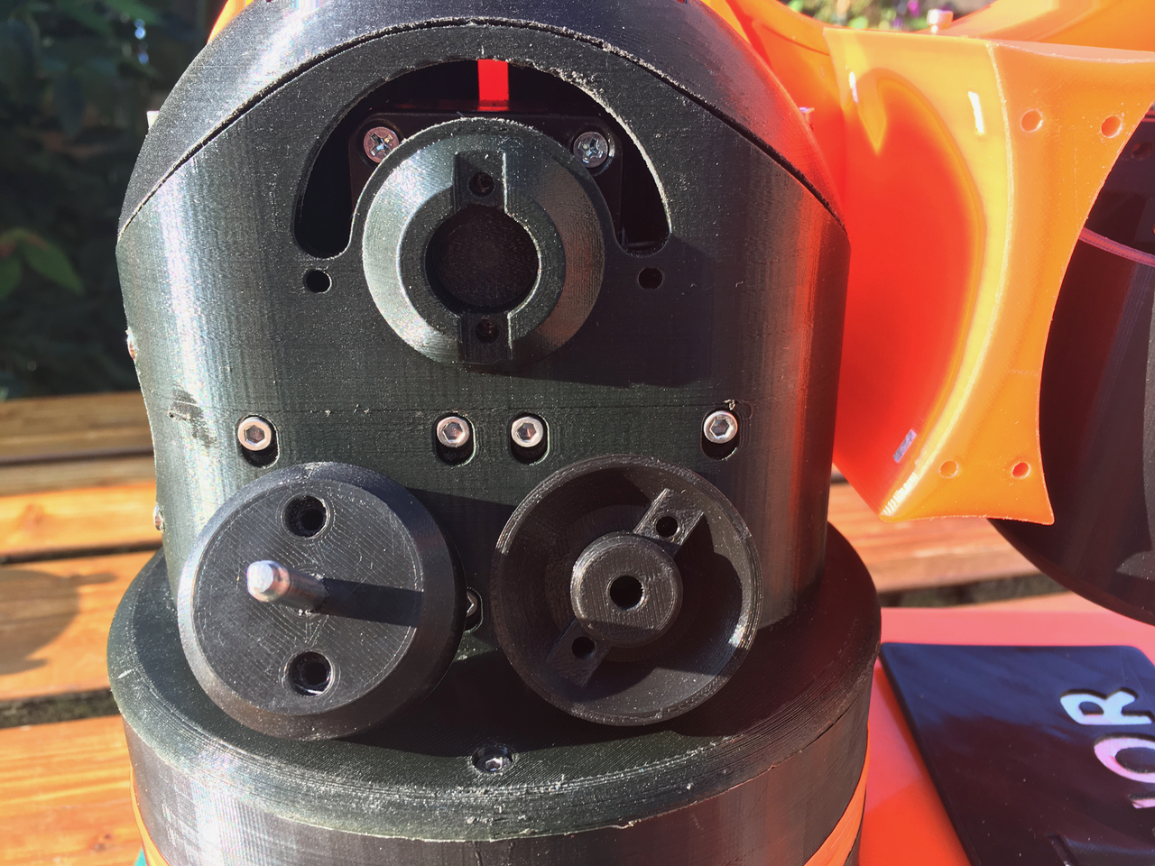
The other side.
![]()
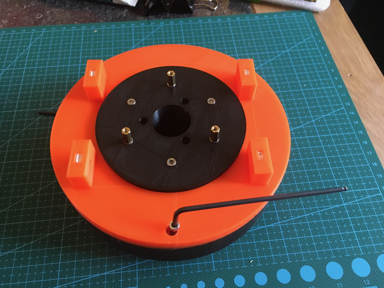
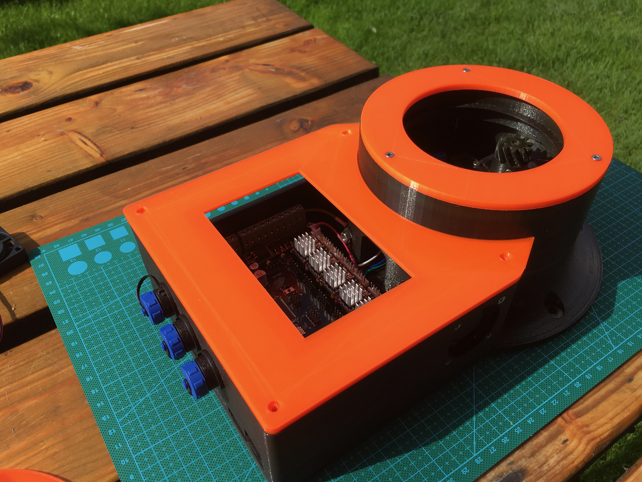
Both axle holders are mounted. You need 20mm screws.
![]()
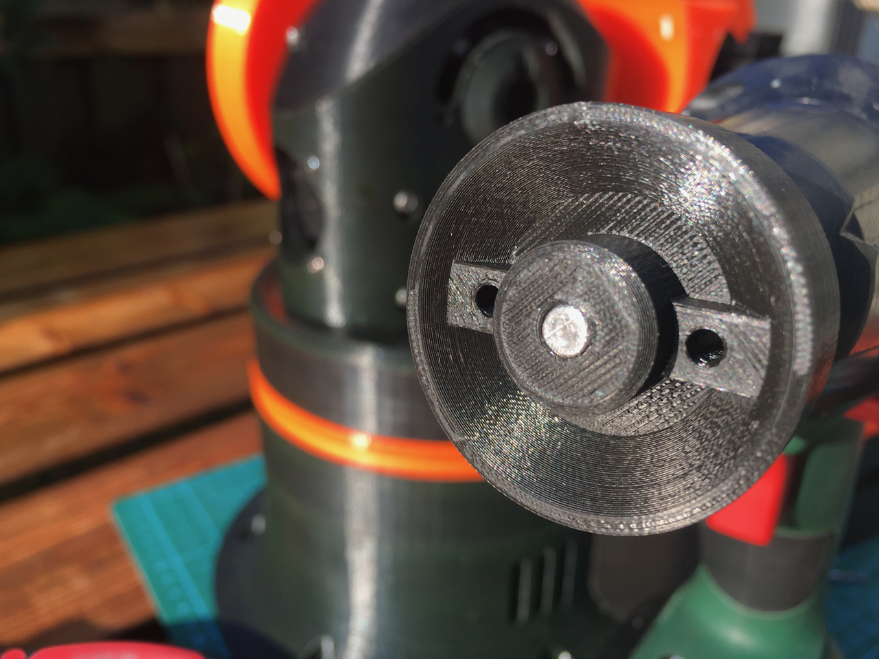
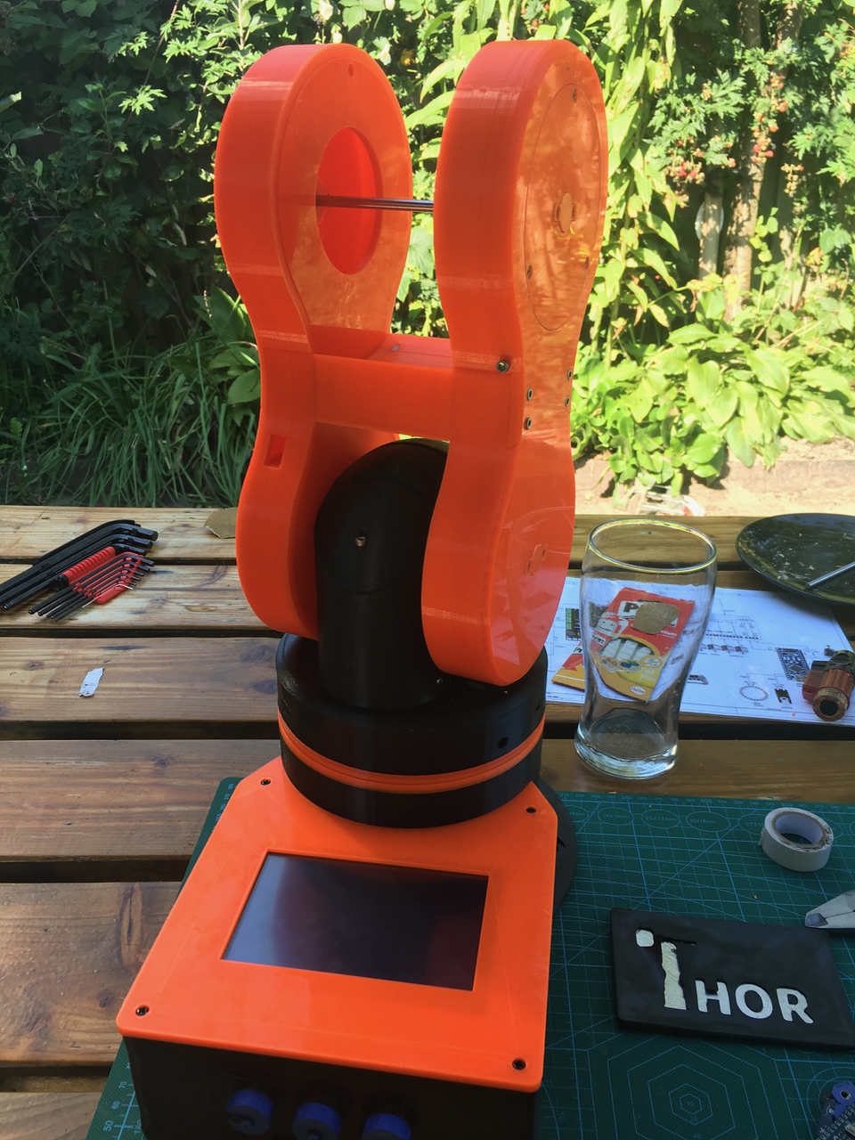
After putting everything back together it feels much sturdier. No wobbling axis anymore.
![]()
The AxleHolder part is available for download: AxleHolder.stl
-
Day 11: Mounting Art 2.
08/27/2017 at 16:08 • 1 commentBelow all the parts of art 2.
![]()
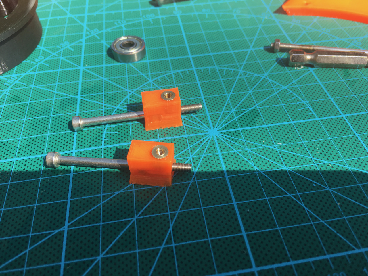
First I had to create the belt tensioner wheel mount. At first I had no clue how to fit those wheels. There is no room for a nut. So I decided to use m3 threaded inserts. I made the hole a little bit bigger. I fitted the insert on a long screw so I could heat up the insert. Then I inserted it into the hole. The plastic melted a little bit and after aligning everything I used some cold water to cool the plastic down.
![]()
The mounts with the threaded inserts.
![]()
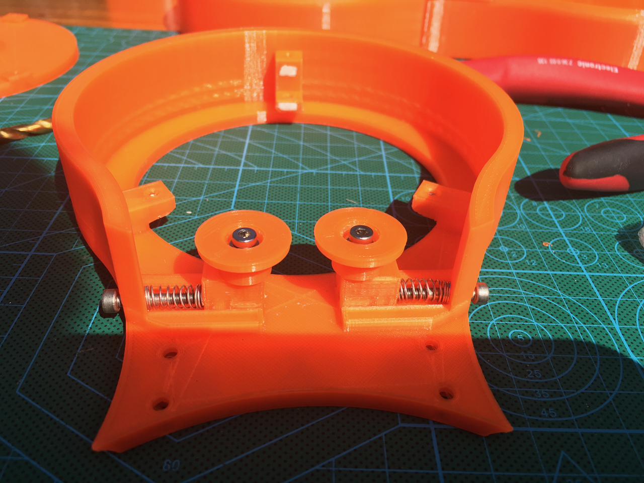
Now it was time to add the belt tension wheels. I also used two halfs of a compression spring (from a pen) to push both belt tensioners to the inside.
![]()
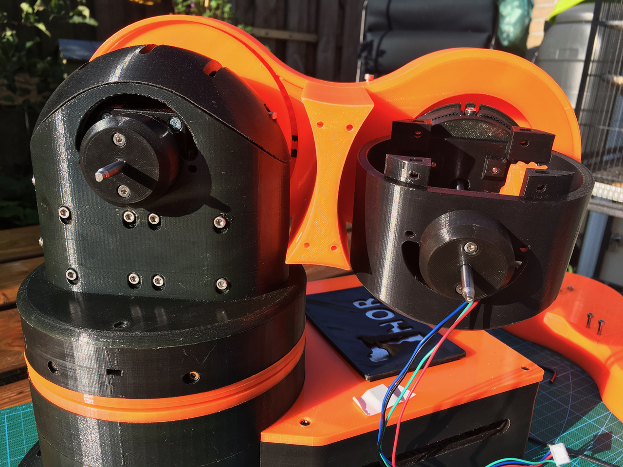
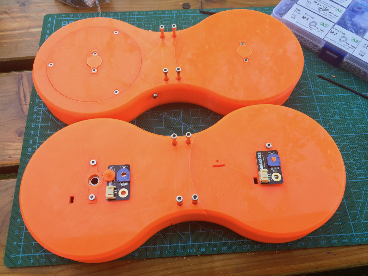
Now it was time to fit all the parts together. I don't like the orange parts for the sensors which have to be glued on the axles. I am going to make the axle a little bit longer and use that for turning the potentiometers.
![]()
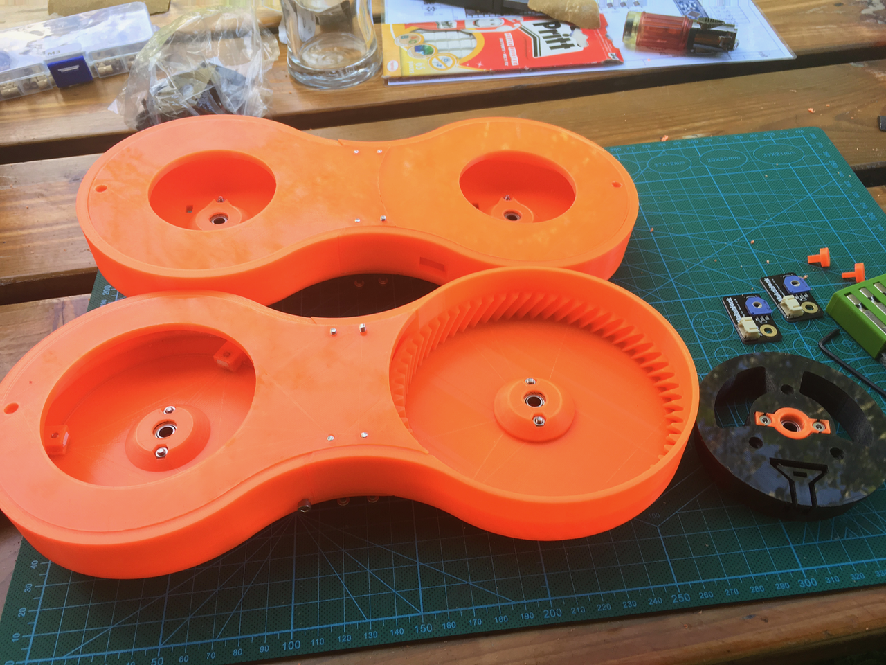
The inside.
![]()
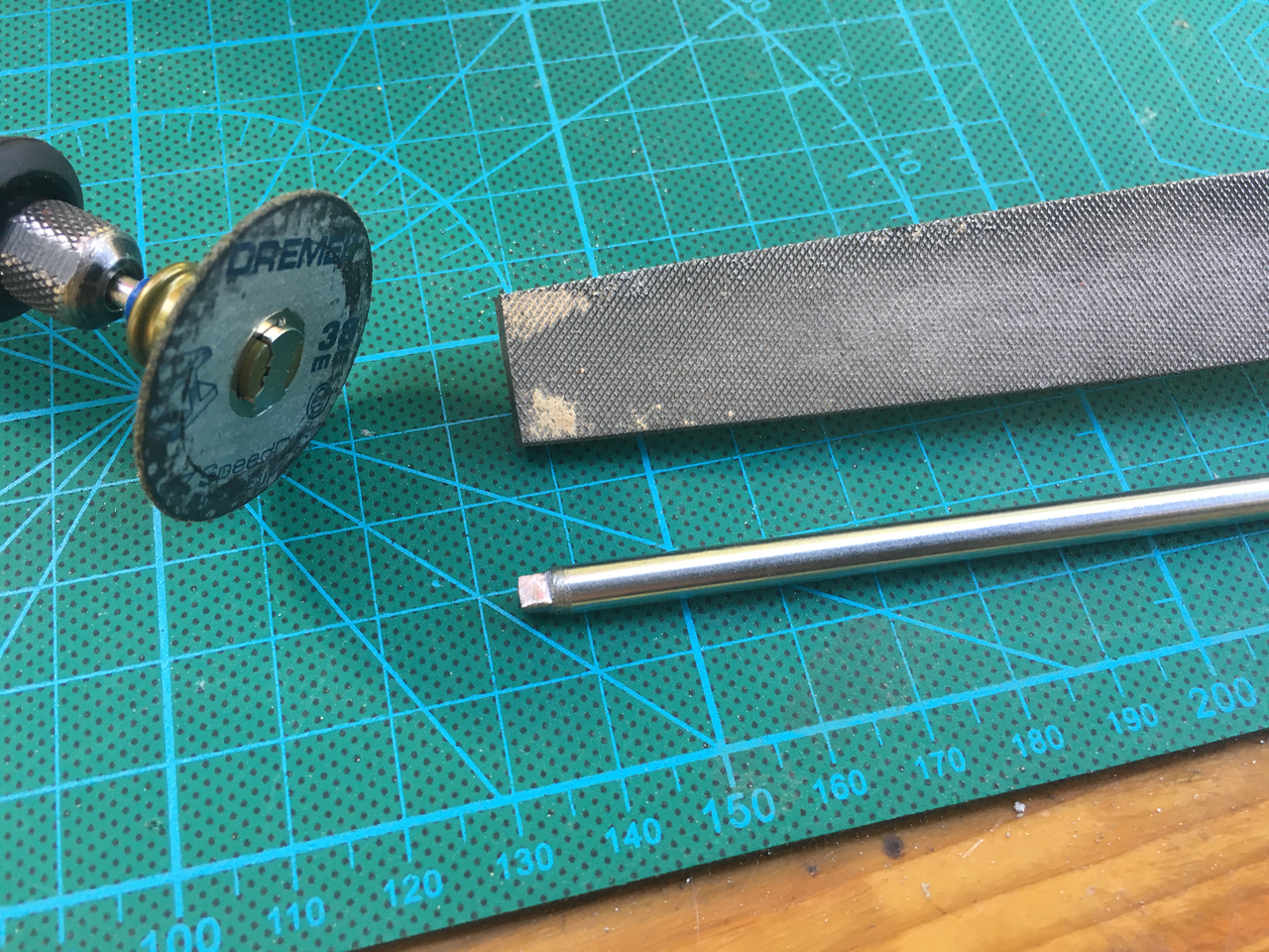
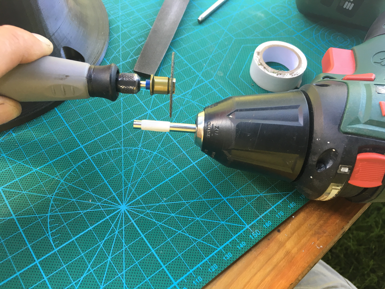
Now it was time to create the axles. I made one side of the 5mm axle a little bit smaller. Just put the axle in a electric screw driver. Use the dremel (or file) to grind the axle to 4mm. Then I used the dremel to flatten one side.
![]()
I fitted the orange parts on art 1 and inserted the axle. The side with the flat area is on the inside.
![]()
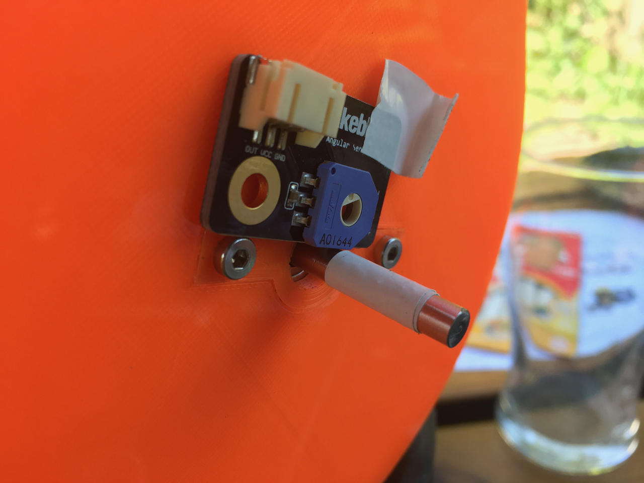
I used some tape on the Axle to mark the length.
![]()
Then I cut the Axle with the Dremel. Use the screwdriver to turn the Axle and keep the running Dremel steady.
![]()
Now insert the Axle the correct way.
![]()
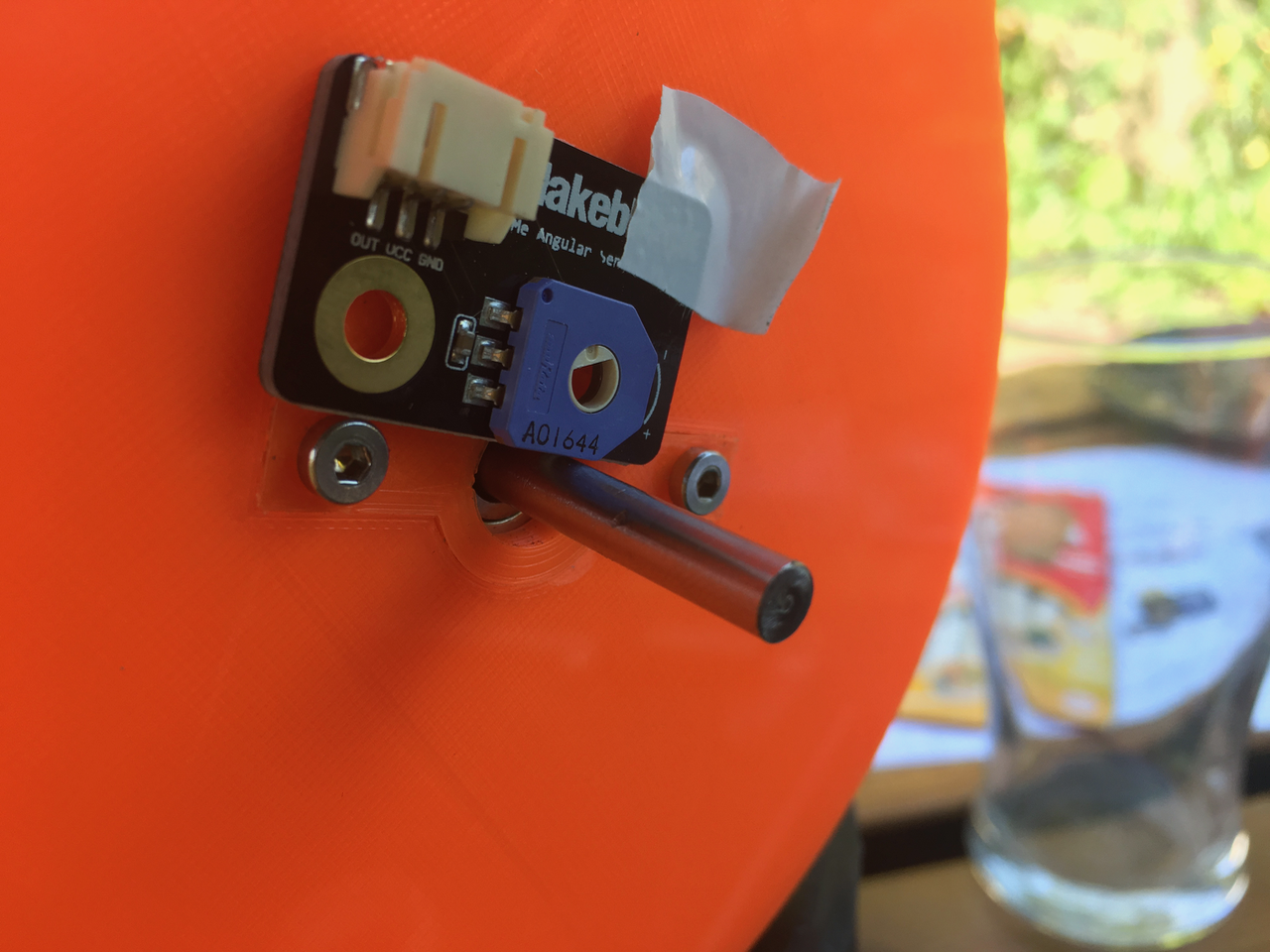
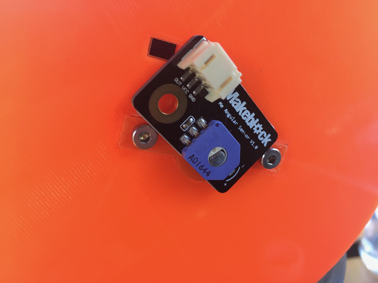
The potentiometer of the sensor fits.
![]()
All three Axles finished. I think I will created an extra plastic part with an extra bearing to mount between art 1 and art 2. This axis uses two small axles because the motors are inside the art 1 housing. On the gear side it is very sturdy. But on the other side it is hanging trough. If I mount a new plastic ring with another bearing to the black or orange part then it will become more firm. But before I will design this I want to be sure that I'am not missing any parts. Without the extra part I'am sure the potentiometer sensor will break.
![]()
-
Day 10: Wiring the base and art 1
08/27/2017 at 15:41 • 3 commentsLast week many parts arrived from China. One of them was the slip ring. Also Danny added the base with the fan holes for a 40x40X10 mm fan.
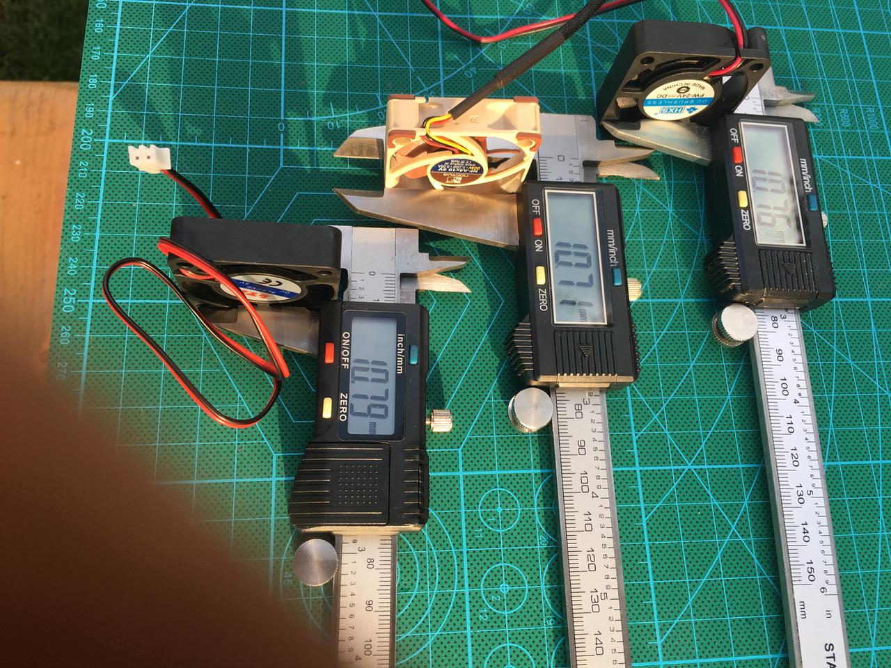
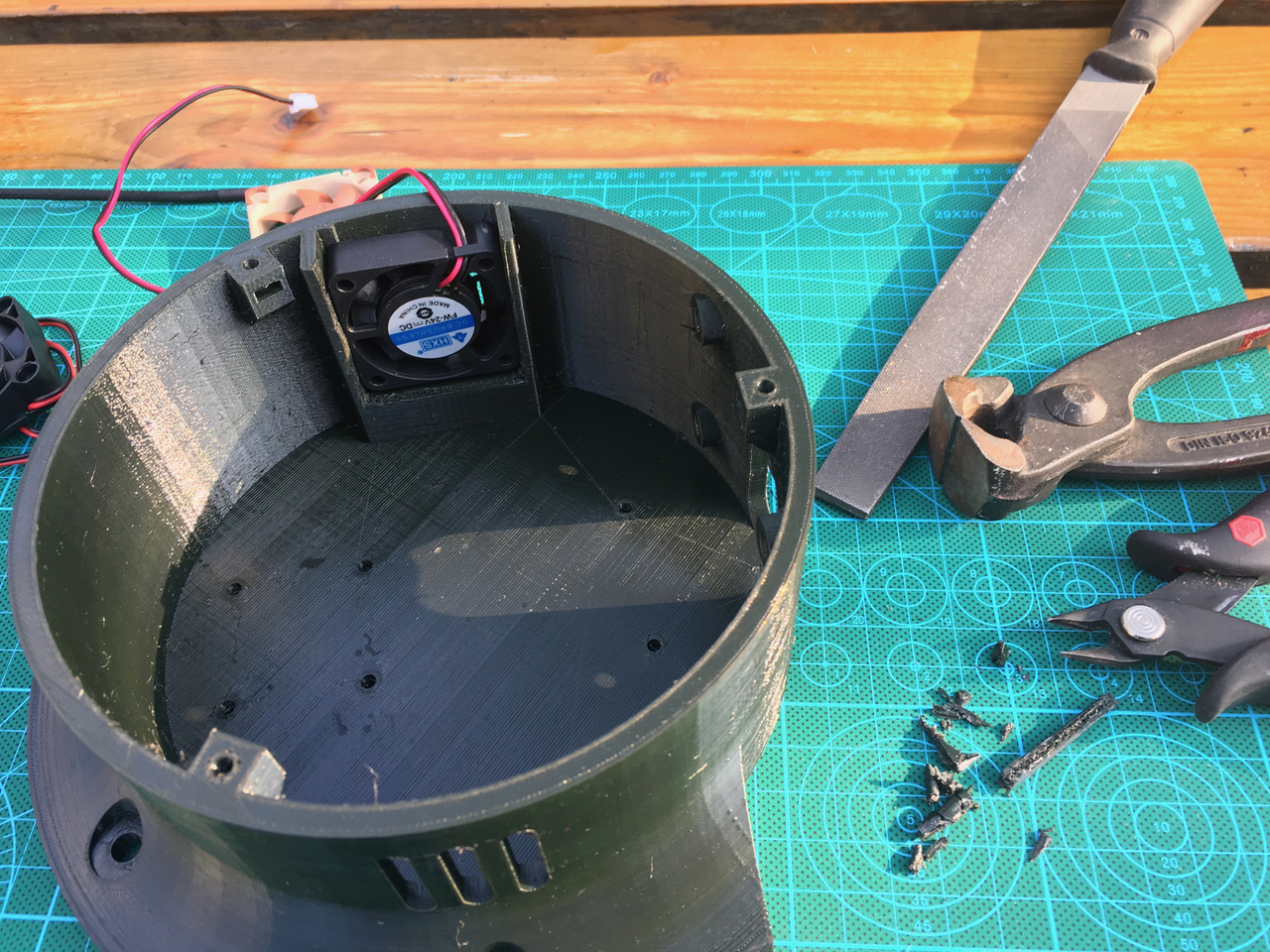
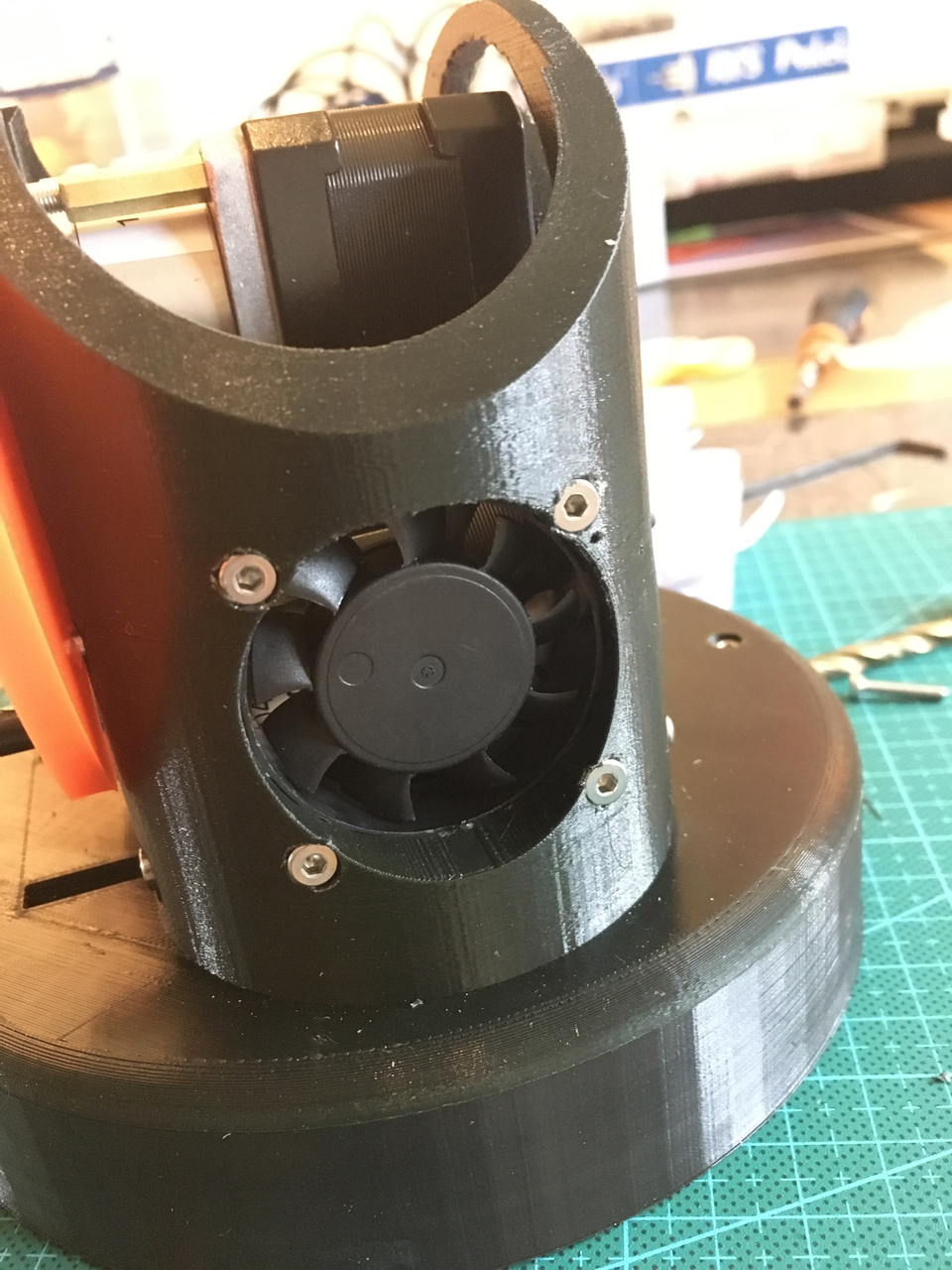
After printing the new base I tried to add the fan. But it didn't fit. All the 40x40x10 mm fans are 10.8 mm high. Why don't they call it a 40x40x11 mm fan.
![]()
The base only accepts 9,8 mm fans.
![]()
So I had to use some pliers to break some plastic away. I used hot glue to mount the fan.
![]()
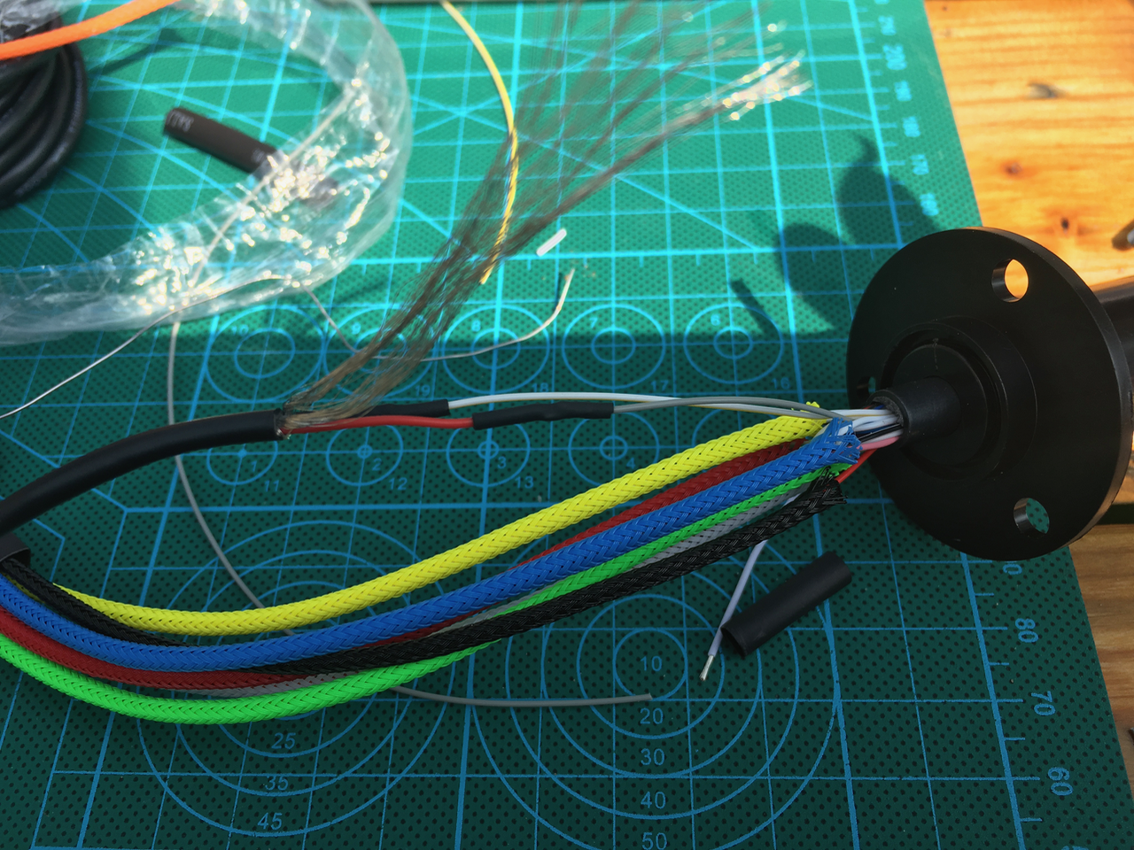
Now it was time to mount the slip ring. The slip ring has 24 wires. I created 5 groups of 4 wires (green, blue, orange, red and white for the stepper motors and a group of 2 wires for the power lines (black) and a group of 2 for the serial communication (orange). I wanted this wires to be shielded. The shield on the foto below is long enough to fit over the remaining wire. I used some copper tape to keep the shielding in place.
![]()
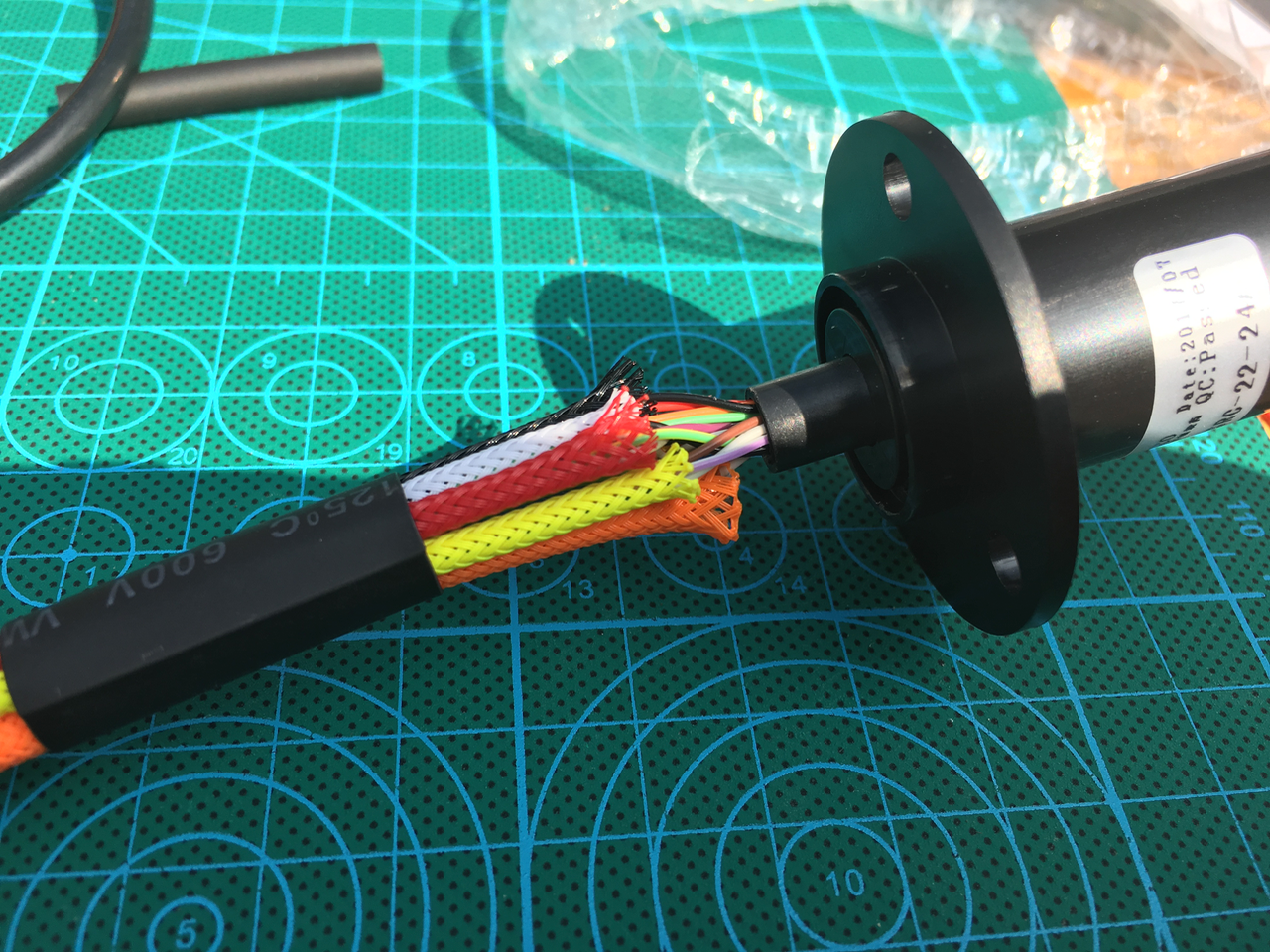
A piece of shrink wrap is used to fix the sleeves.
![]()
On the other end I used also some sleeving. The orange serial cable is longer because I want to be able to put the Nextion display on the table with all the wires attached.
![]()
I used the old base (without the fan holes) so I could do the sleeving of the upper part. Also the bottom wires are fitted with connectors.
![]()
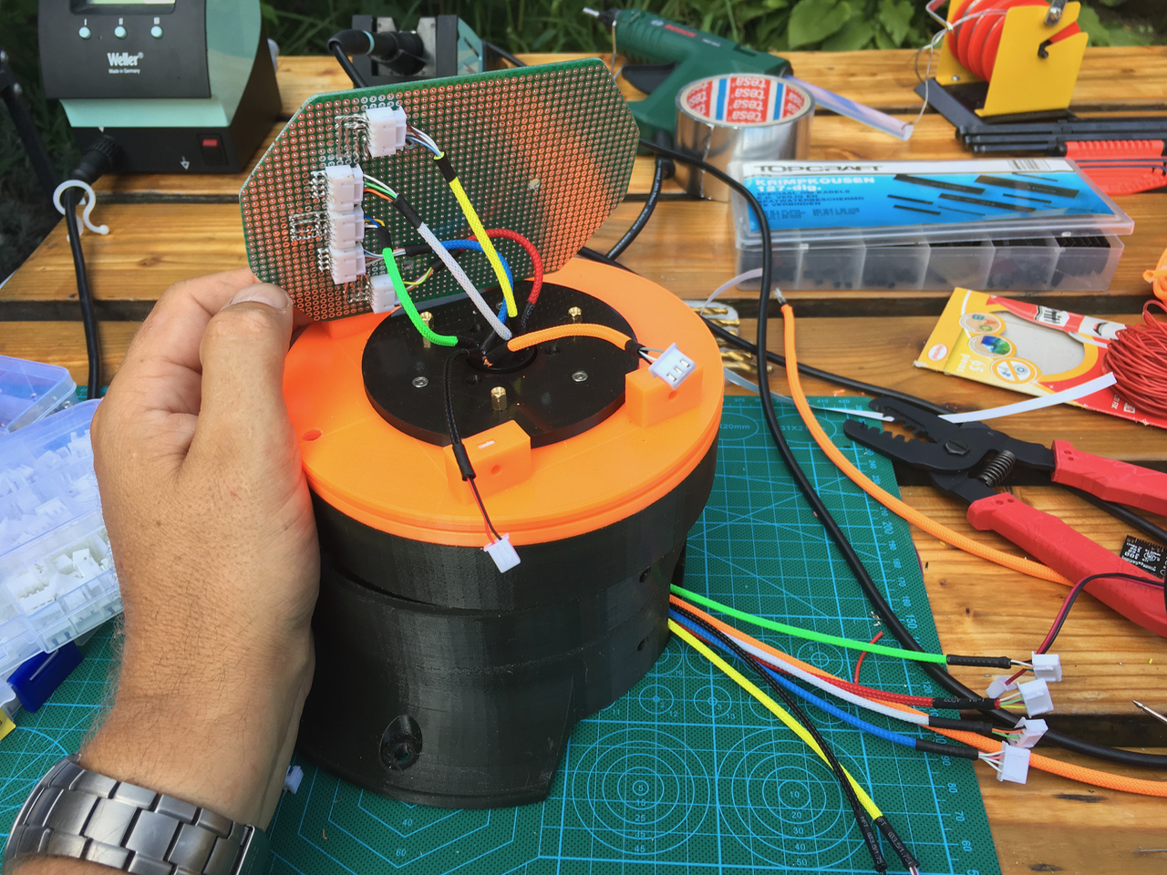
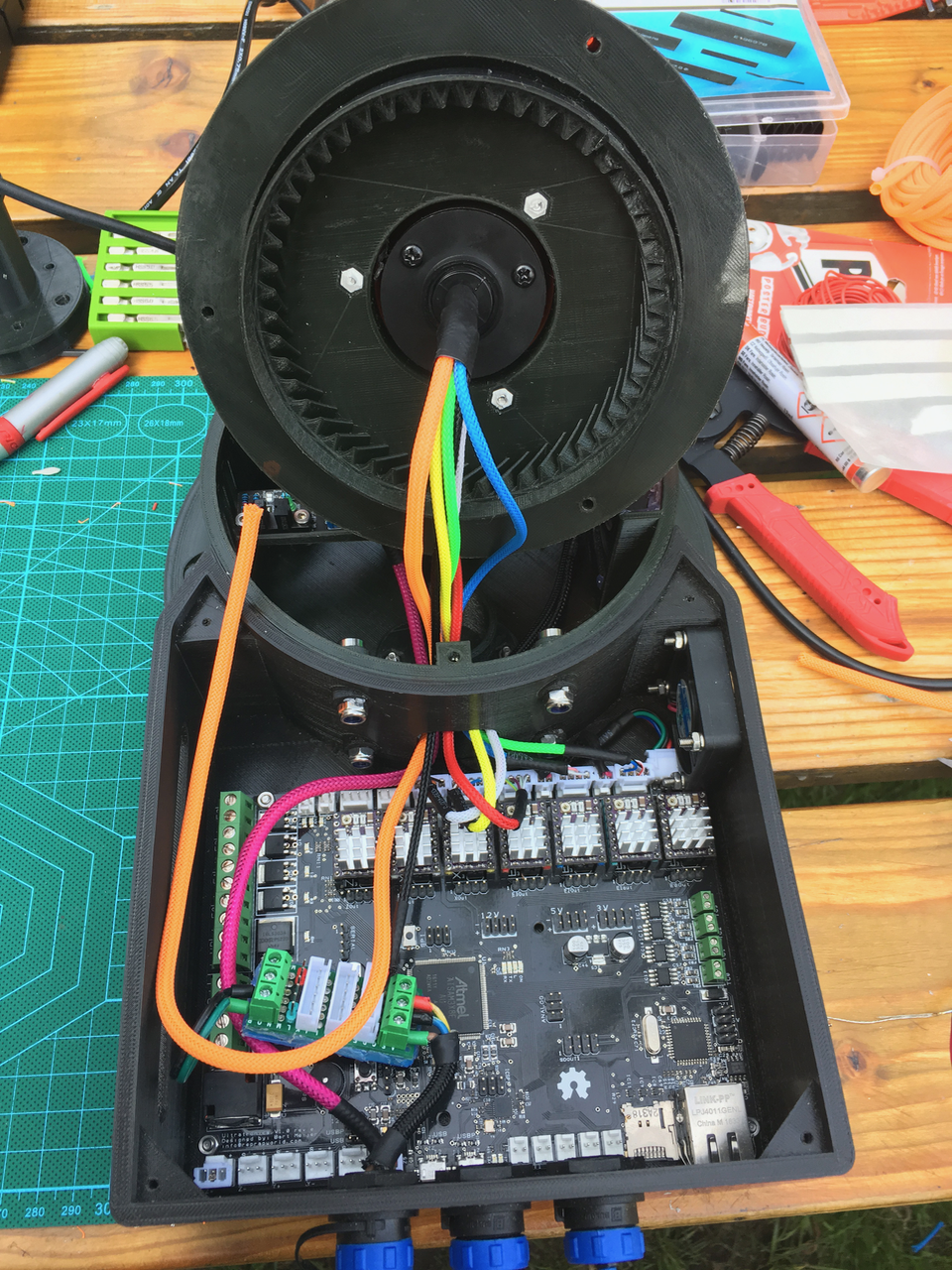
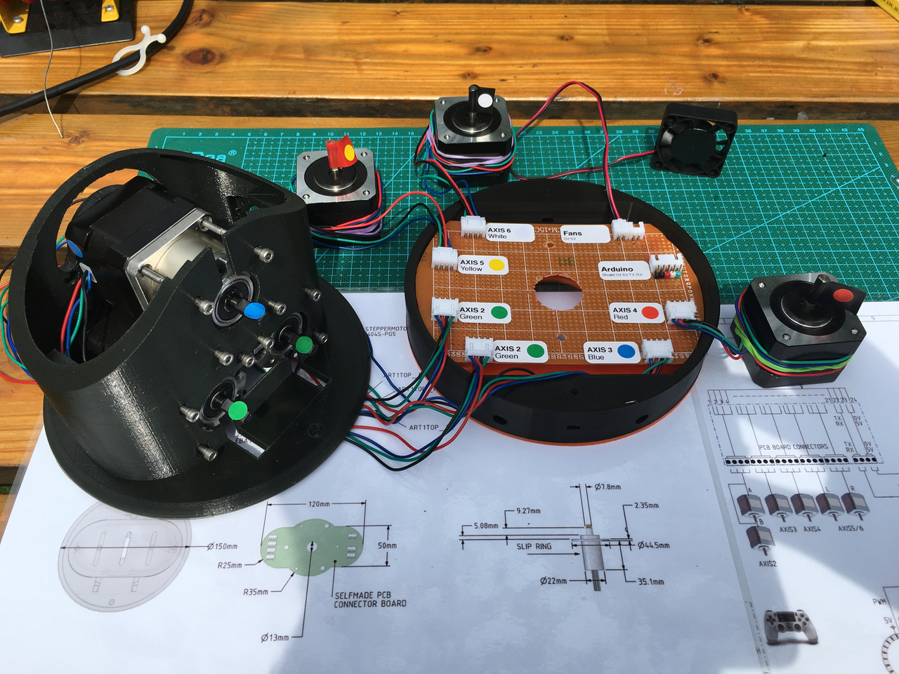
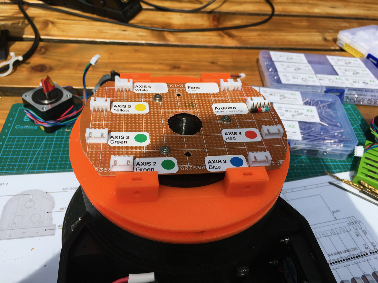
The top ones are fitted with connectors. I created a new PCB. All the stepper motor wires are on the left side. So there is room for step down convertor on the right side. I am going to use 24V power wires trough the slip ring. So I need a step down convertor above the slip ring to change it to 5V. This way I'am not restricted by the 2A max slip ring wires (24V x 2A = 48W, 5V * 2A = 10W). I think I need more then 10W for the arduino, sensors, led ring and servo.
![]()
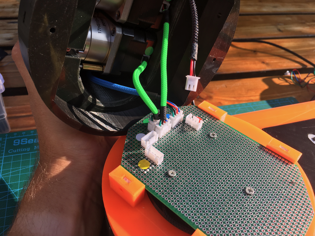
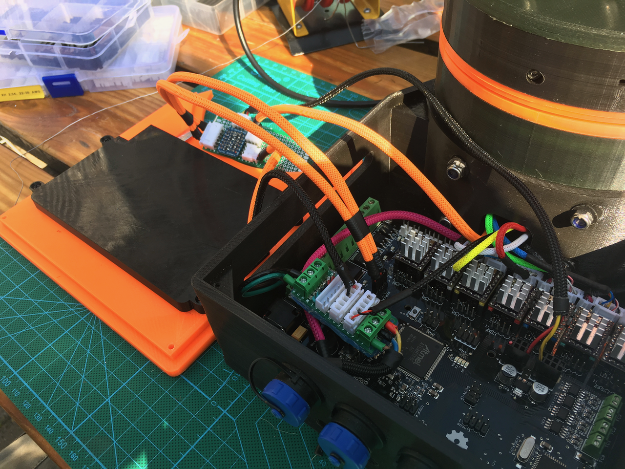
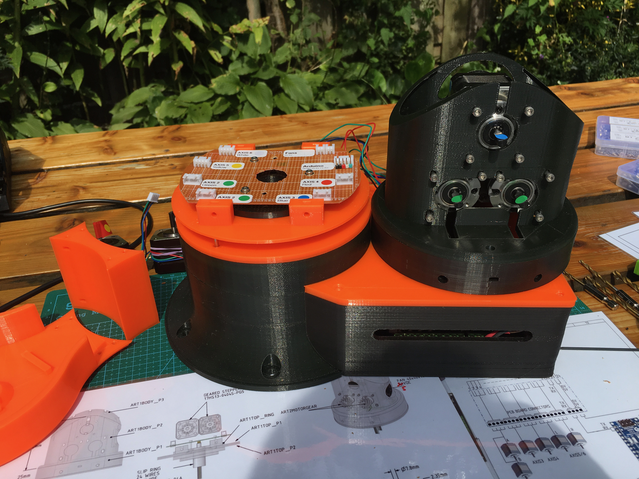
Now it was time to mount the art 2 part with al its wires on the base. The pink wire is used for the sensors. I made a small PCB (bottom left). (Green = 24V, Black = 0V, Red = 5V). This board is also used to power the Nextion and the 24V line though the slip ring.
![]()
The wires of the stepper motors are also sleeved and fitted with connectors. The connectors are arranged in such a way that the will fit in the gap.
![]()
Everything fits.
![]()
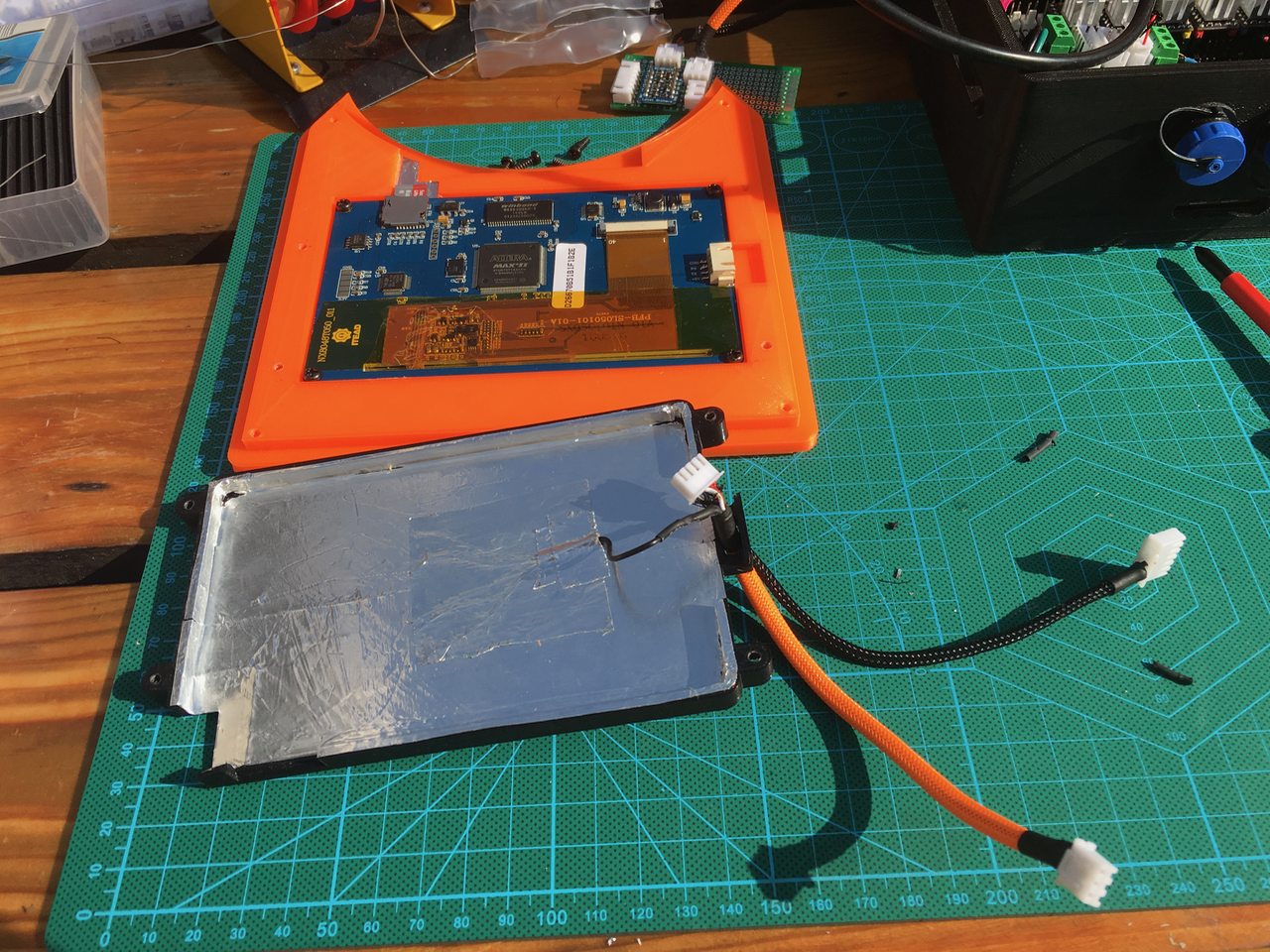
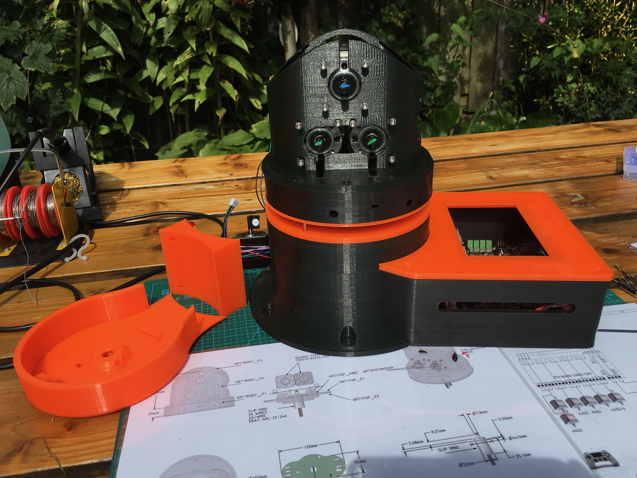
I still had to connect the Nextion. I added some alu tape on the inside of the Nextion display cover as a shield. (Don't know if it will help).
![]()
I created a small PCB (just above the Nextion display) with a power level convertor. The Ultratronics uses 3.3V and the Nextion and Arduino inside the arm are using 5V. The Nextion display is powered with the 5V from the power supply. The 24 line is used to power the top part of the arm. I want to add a Emergency button on the powersupply case which will cut the 24V line. This way the Nextion display can stay on.
![]()
Yes! It is still working :-)
![]()
-
Day 9: Mounting the Nextion display
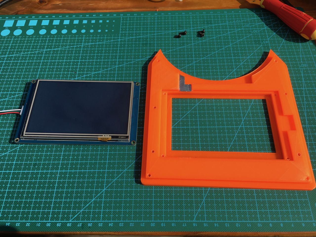
08/27/2017 at 15:03 • 10 commentsToday it was time to mount the Nextion Display in its frame. With a file I created a hole in the orange part so there is room to remove/insert Micro SD cart. I used a piece of all tape to smoothen the surface. This way it was easier to remove the cart.
![]()
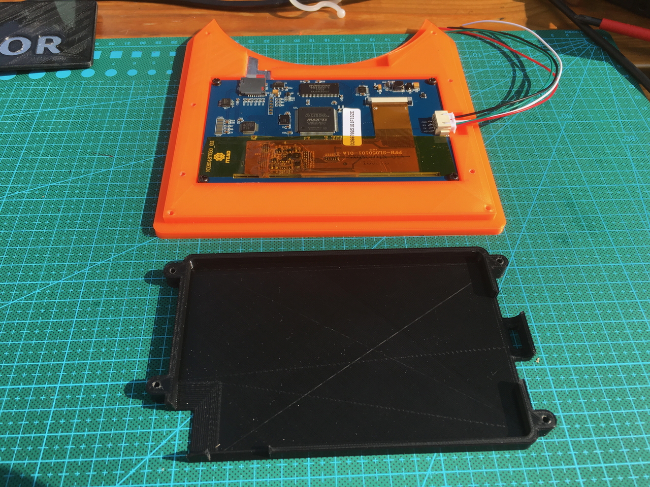
I didn't like an unprotected bottom. Its to fragile. I created a bottom cover for the Nextion Display. It has an air intake on the bottom left side. An hole for the SD cart on the bottom side. And on the right side there is room for the warm air to escape. There is also a cable guide.
![]()
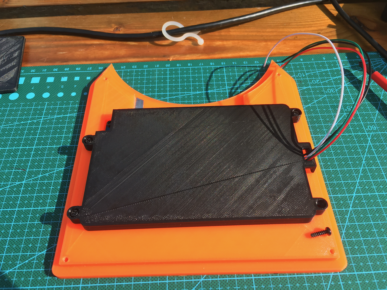
Below the bottom part mounted. (The wires will be replace by shielded ones).
![]()
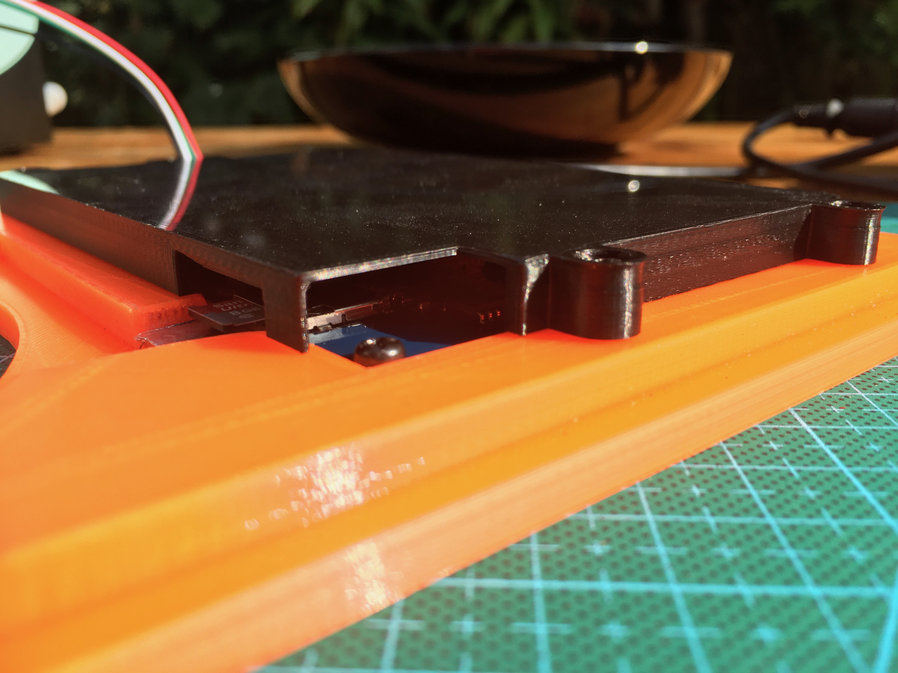
The air intake and the hole for the SD cart.
![]()
The covers can be downloaded here. I used Fusion 360. I included all possible export formats.
I Also created a top cover to protect the screen during the build. (But I'am going to reprint it because I left the black part in the sun and now it is curling up.
![]()
-
Question: Powering the parts inside the arm.
08/19/2017 at 15:55 • 0 commentsAmperage
I have to wait for some parts (among which the slip ring) before I can wire the PCB inside the arm. So I was thinking about the maximum amperage I need for all the parts inside the arm:
- 2x 5V fans (2x 0.14A = 0.28A)
- Arduino Uno (0.1A)
- 6 Rotation sensors (0.1A)
- Servo (0.5 to 1 amp?)
- Ledring (24 NeoPixels at full brightness × 0.06A = 1.4 Amps)
I would also like to add a few MPU9250 9-AXIS Gyro Accelarator Magnometer Sensors in the future.
5V through slip ring.
The slip ring wires can handle 2A max. Danny uses one of the wires for 5V. This way it can handle 2A x 5V = 10W. I don' think this is enough.
24V through slip ring and 5V step down convertor on PCB
Wouldn't it be better to use 24V for this wire. This way it can handle 2A x 24V = 48W. I could convert it back to 5V on the PCB above the slip ring. This way I have 48W / 5V = 9.6A.
The top of the PCB is cooled by the fan. So cooling isn't a problem. If I mount the PCB a little bit lower there is more than enough room for the step-down convertor.This also means that if I hit the emergency switch in the power unit I only need to cut the 24V line. The 5V line can be left intact to power the Nextion display.
Question:
What do you think about this? Are there any disadvantages I didn't think about?
-
Day 8: Finishing Axis 1
08/19/2017 at 14:38 • 0 commentsAfter printing all the parts for AXIS 1 it was time to put it all together.
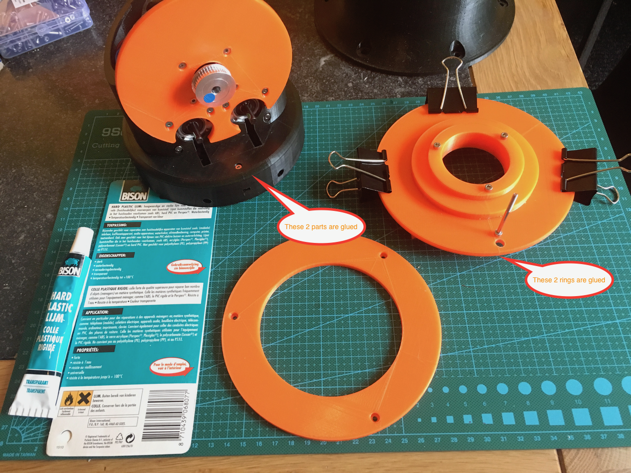
First I had to glue some parts together. I used the screws to align the parts.
![]()
I added a hole in the orange ring. I used the bearing cover ring for positioning the hole.
![]()
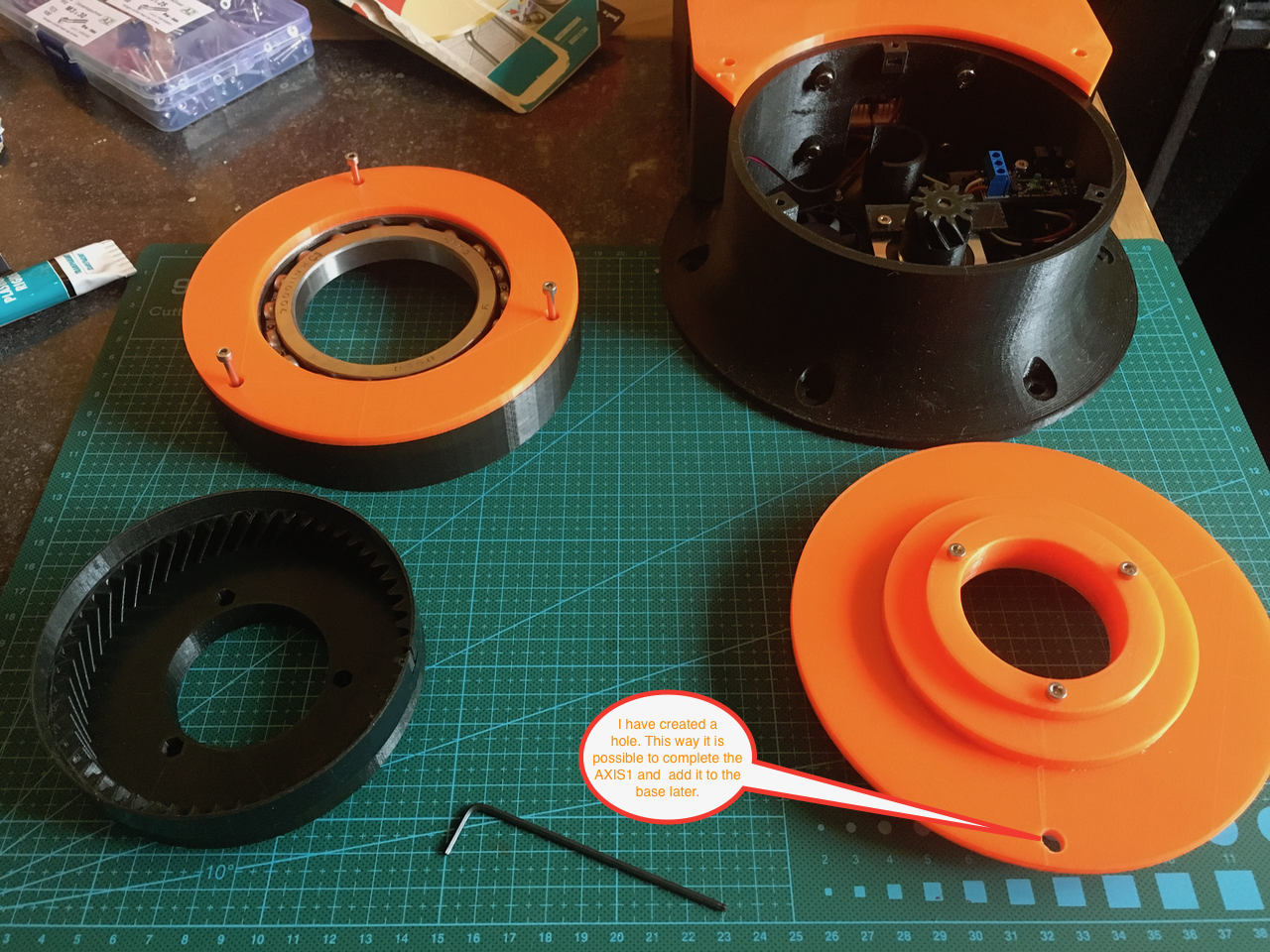
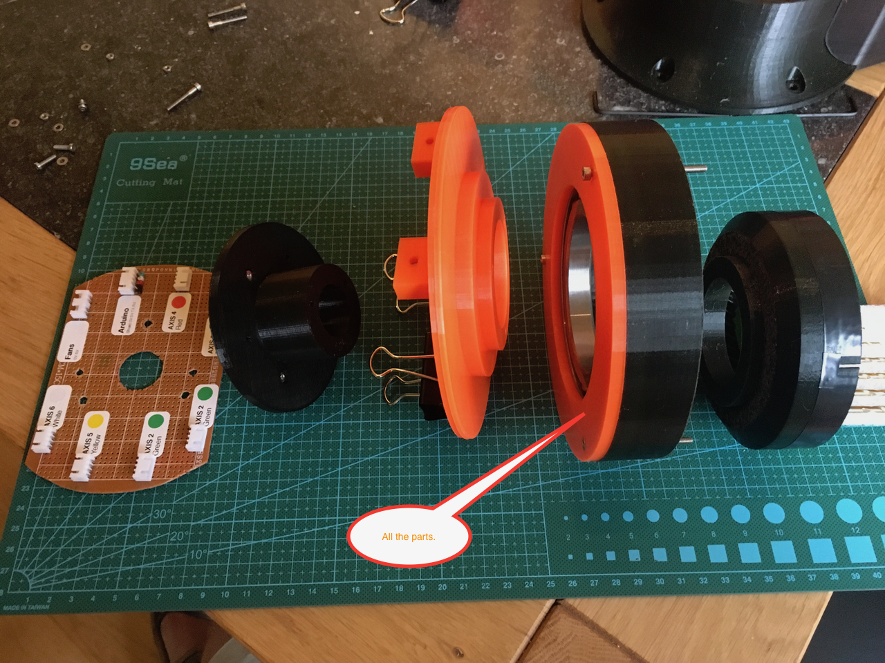
All the parts that will be mounted together. I added a few drops of glue between the black and orange bearing ring. This way the ring can't the screws holes are aligned and it will be easier to mount AXIS1 to the base. I also added some ball bearing.
![]()
![]()
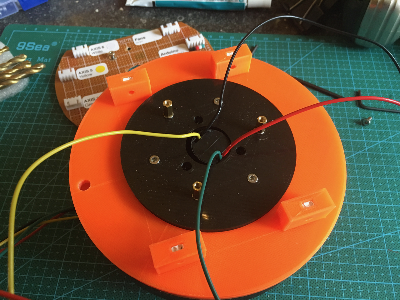
Axis 1 from the top side. (I changed the screw and nuts to mount the PCB to PCB standoff pillars).
![]()
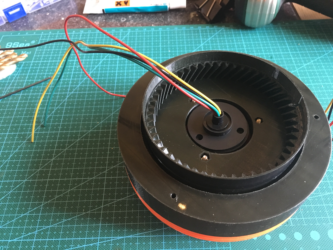
And from the bottom side. De inner black tube is used to mount the slip ring.
![]()
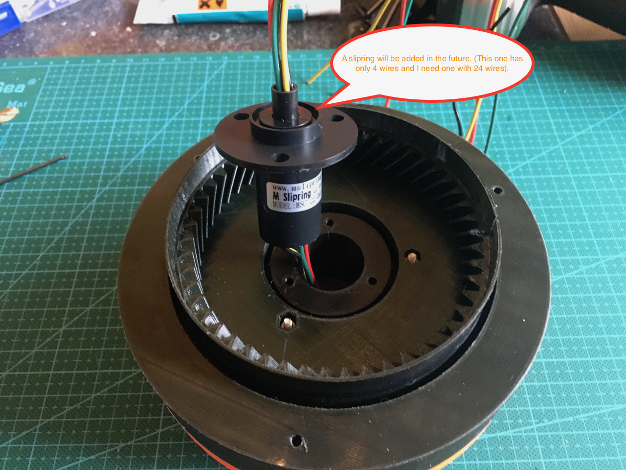
An example of the slip ring (this one doesn't have enough wires).
![]()
If the slip ring is inserted it will look like this. The part with the wires can rotate. The little gap on the top right side of the gear is used for the optical gate sensor.
![]()
The same slip ring from the top.
![]()
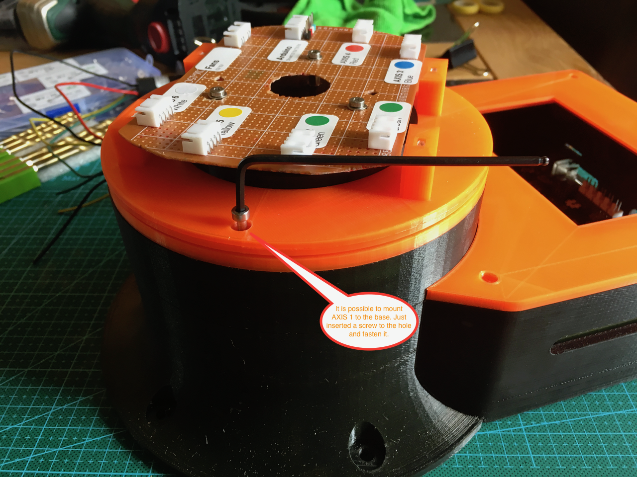
After mounting the PCB it was time to put AXIS 1 on the base. The little hole in the top ring can now be used to insert and fasten the screws.
![]()
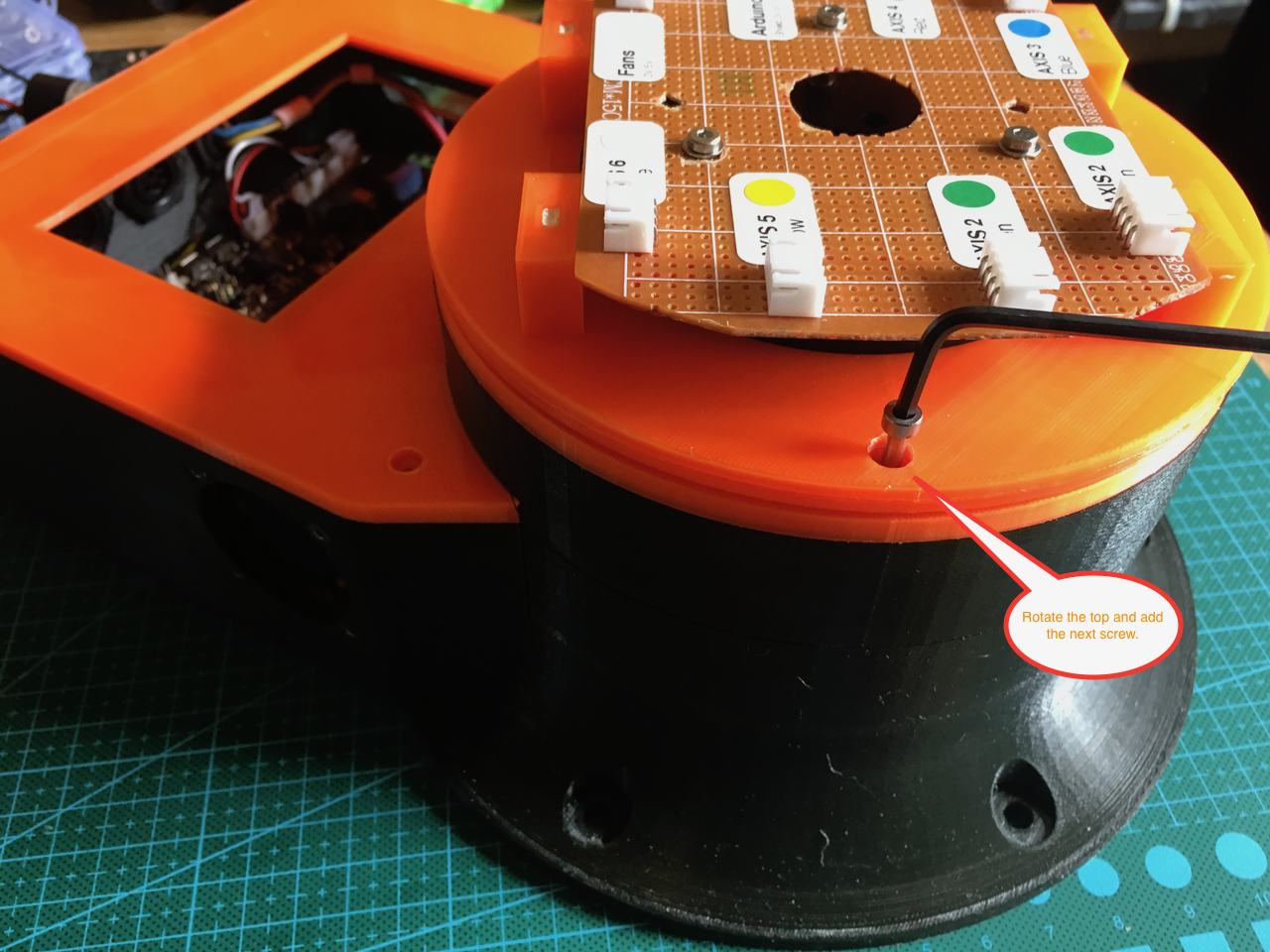
Just rotate the top ring 120 degrees and insert the next screw.
![]()
I didn't add the 10 turn potentiometer in the base yet. Because I still have to create the correct firmware It can now rotate continuously.If I add the potentiometer it is limited to one rotation. One rotation of AXIS 1 is about 8 turns of the potentiometer. Without support for this in the firmware it could (and would) break something.
Now it was time to turn the power on and it worked perfectly.
-
Day 7: Mounting the Axis 2 and 3 stepper motors in ART2
08/17/2017 at 17:55 • 1 commentToday I printed the ART2BODYACOVER_01 so I could build the ART2 completely.
Yesterday I was planning to use nuts and lock washers. But there is no room to work inside the printed part. So I changed it and used a simpler and better way.
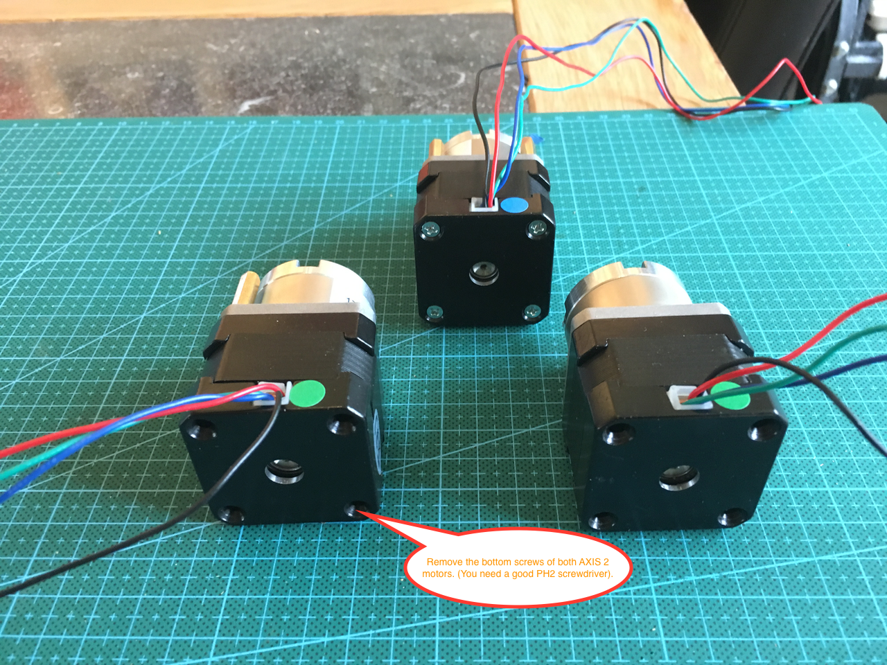
Remove the bottom screws of the AXIS2 Motors.
![]()
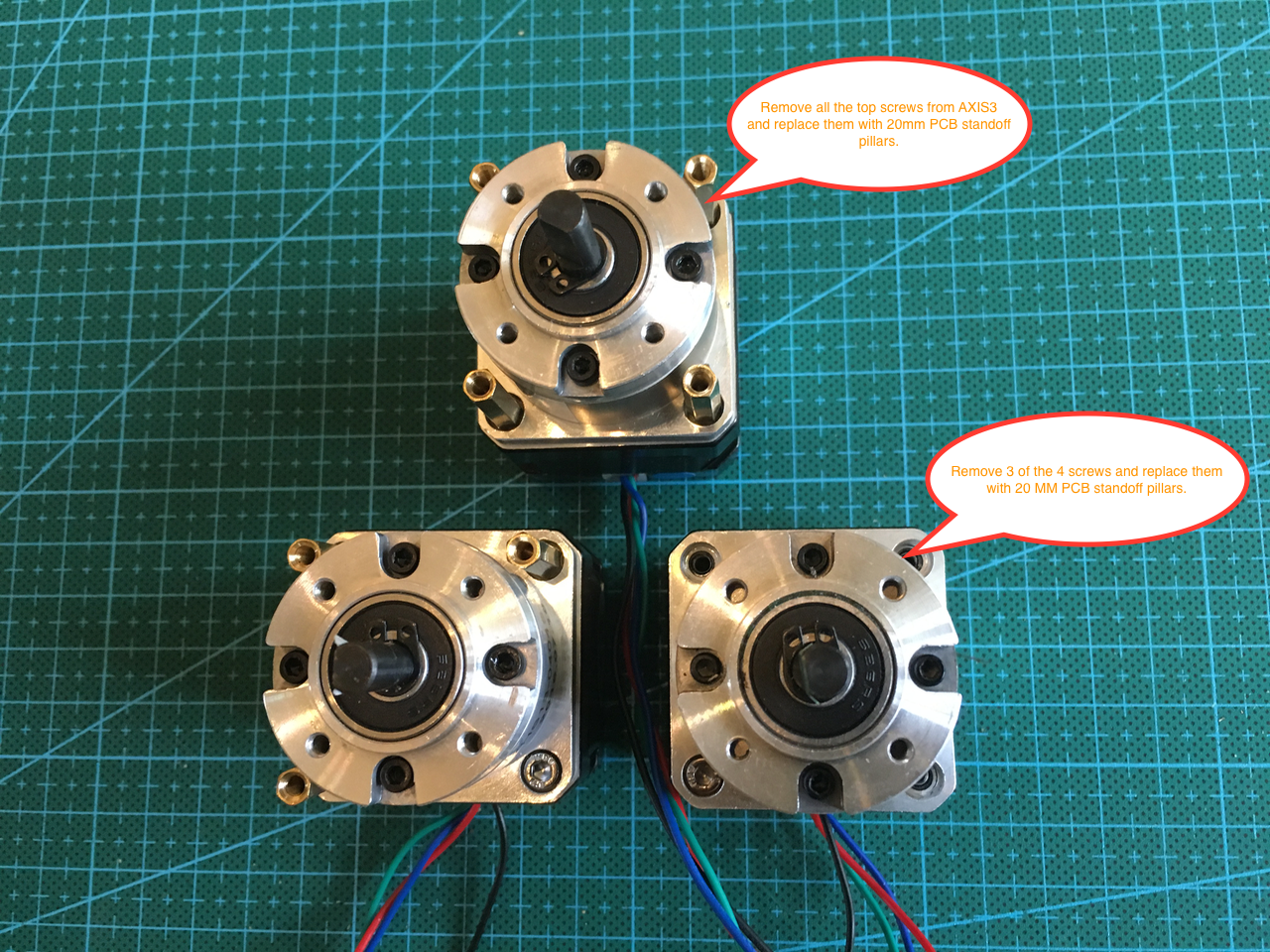
Remove 10 of the 12 top screws.
![]()
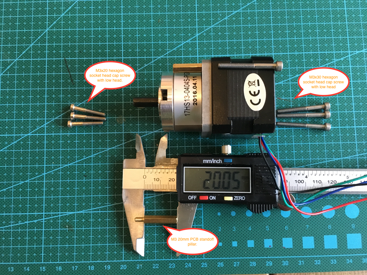
I replaced the top screws with M3 20mm PCB standoff pillars. This way I could secure the gearbox before inserting the motors in the printed part.
![]()
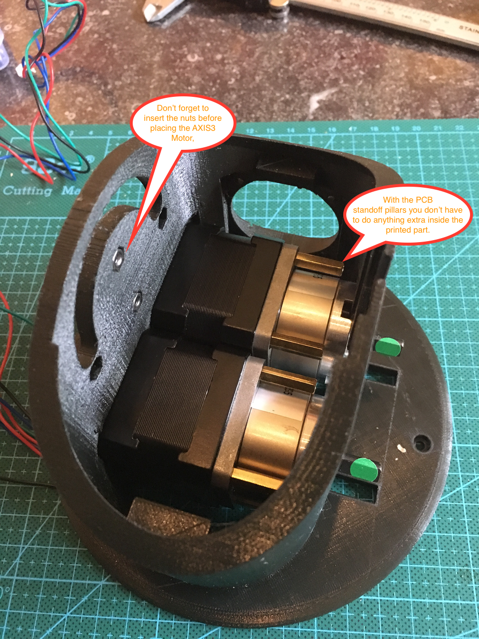
Don't forget the nuts on the inside.
![]()
Add the backside screws.
![]()
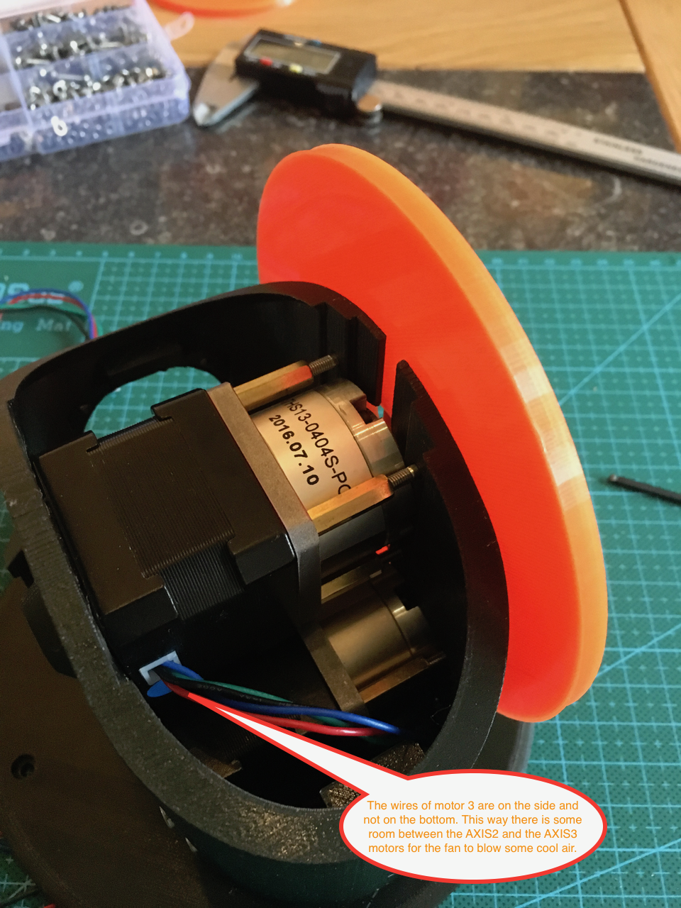
Make sure you add the AXIS 3 motor before mounting the orange ring and adding the top screws of the AXIS 2 motors. Leave some room between both layers of motors for the fan to cool them.
![]()
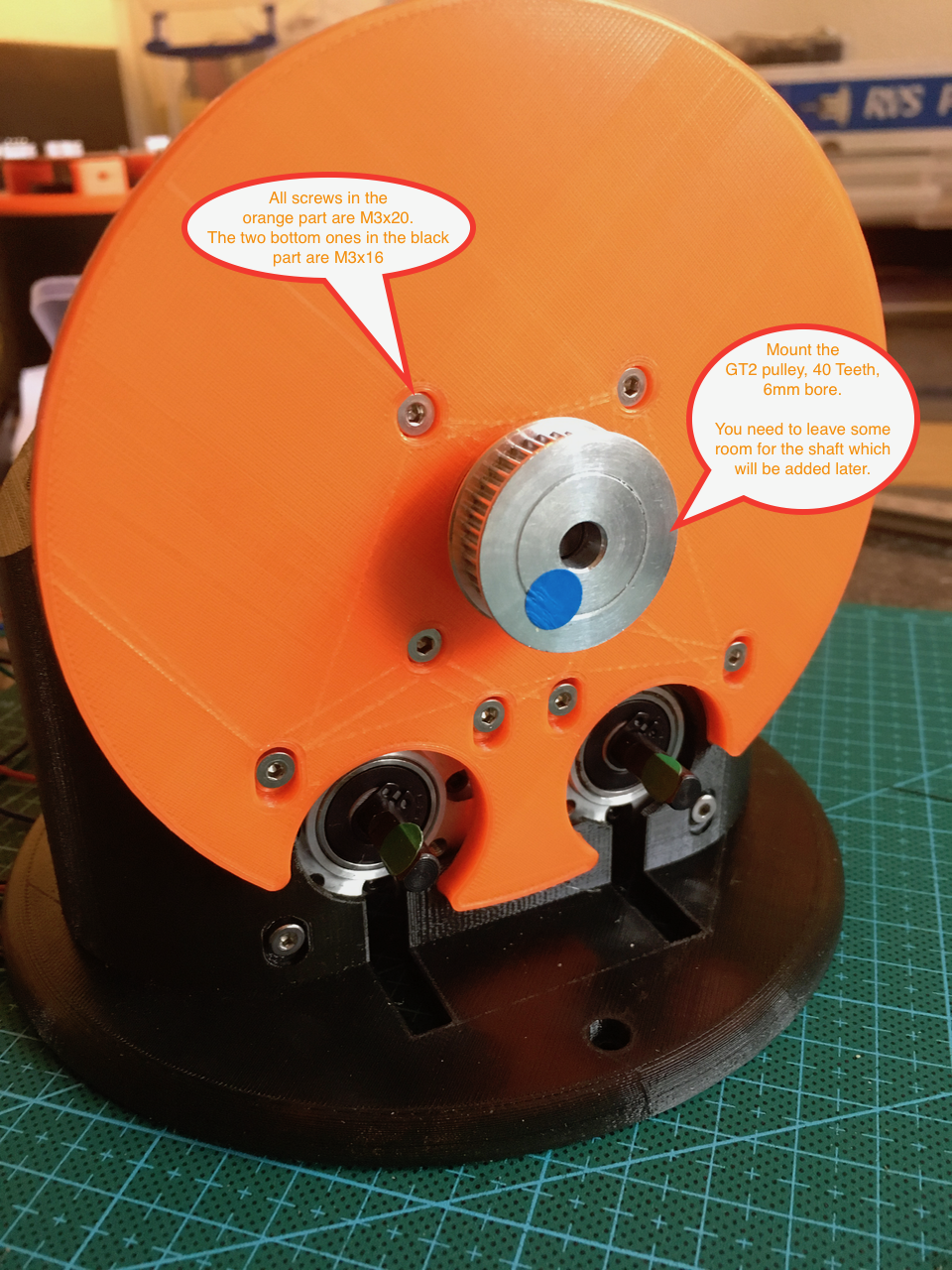
Mount the ring and the stepper motors with the top screws. By using the PCB standoffs is is much easier to adjust the AXIS2 motors. Just loosen the top an back screws and press on the motors.
![]()
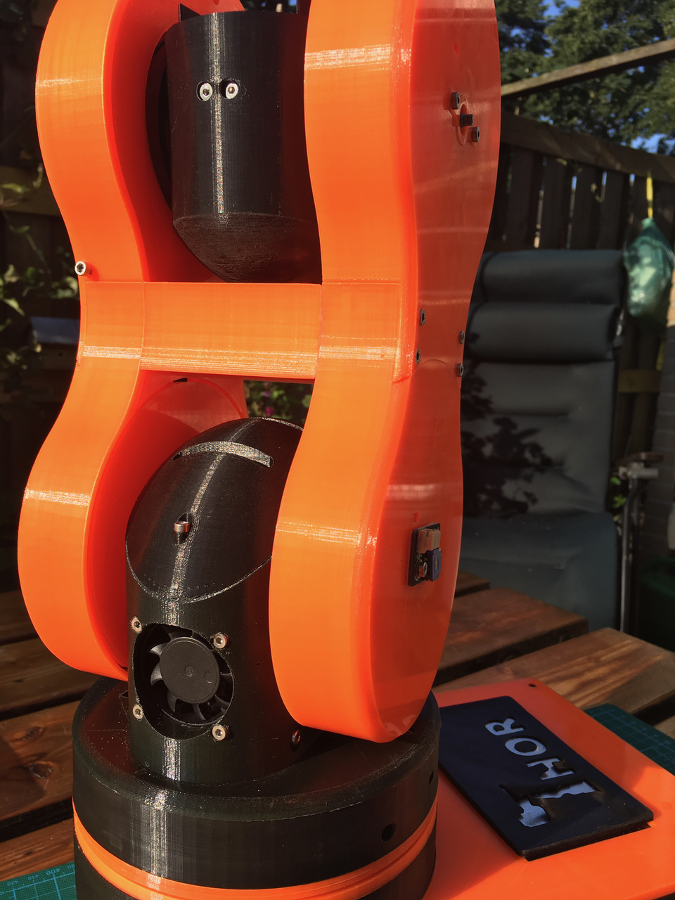
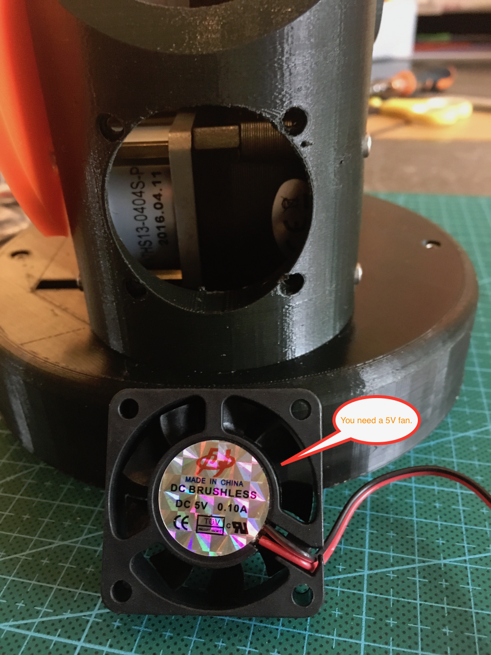
Now it was time to add the fan. You need a 5V fan instead of the 24V on Danny's sheets. There is no room for a 24v wire inside the 24 wire slip ring. 5 steppers x 4 wires, ground, 5V, TX and RX = 24 wires. (Both Axis 2 motors are connected with the same wires).
![]()
The fan is mounted. I had to make the screw holes a little bit bigger.
![]()
Tomorrow I want to finish the AXIS1 and the base. The printer is busy printing the last part..
-
Day 6: Base bearing and Axis 2 (pcb and motors)
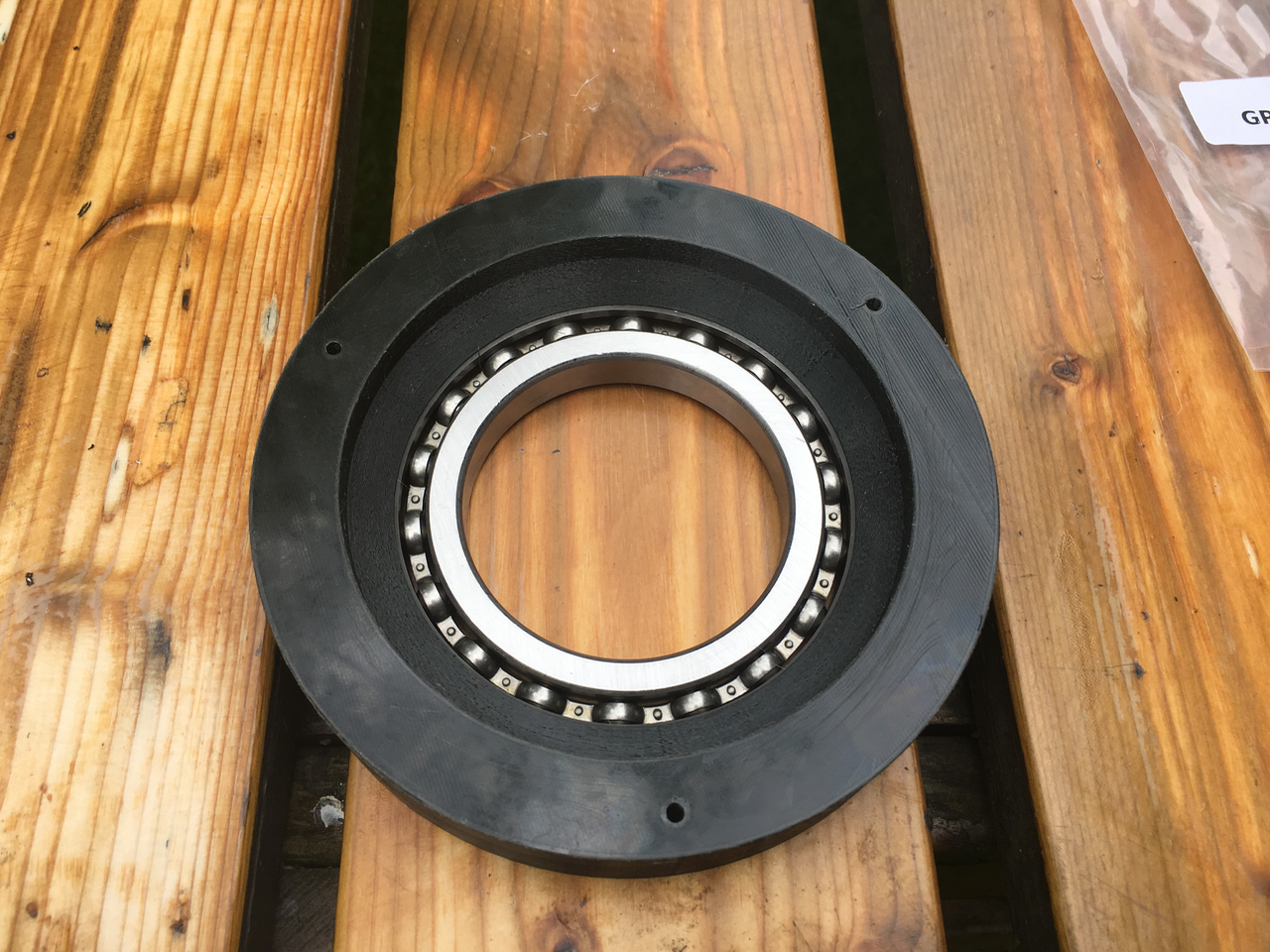
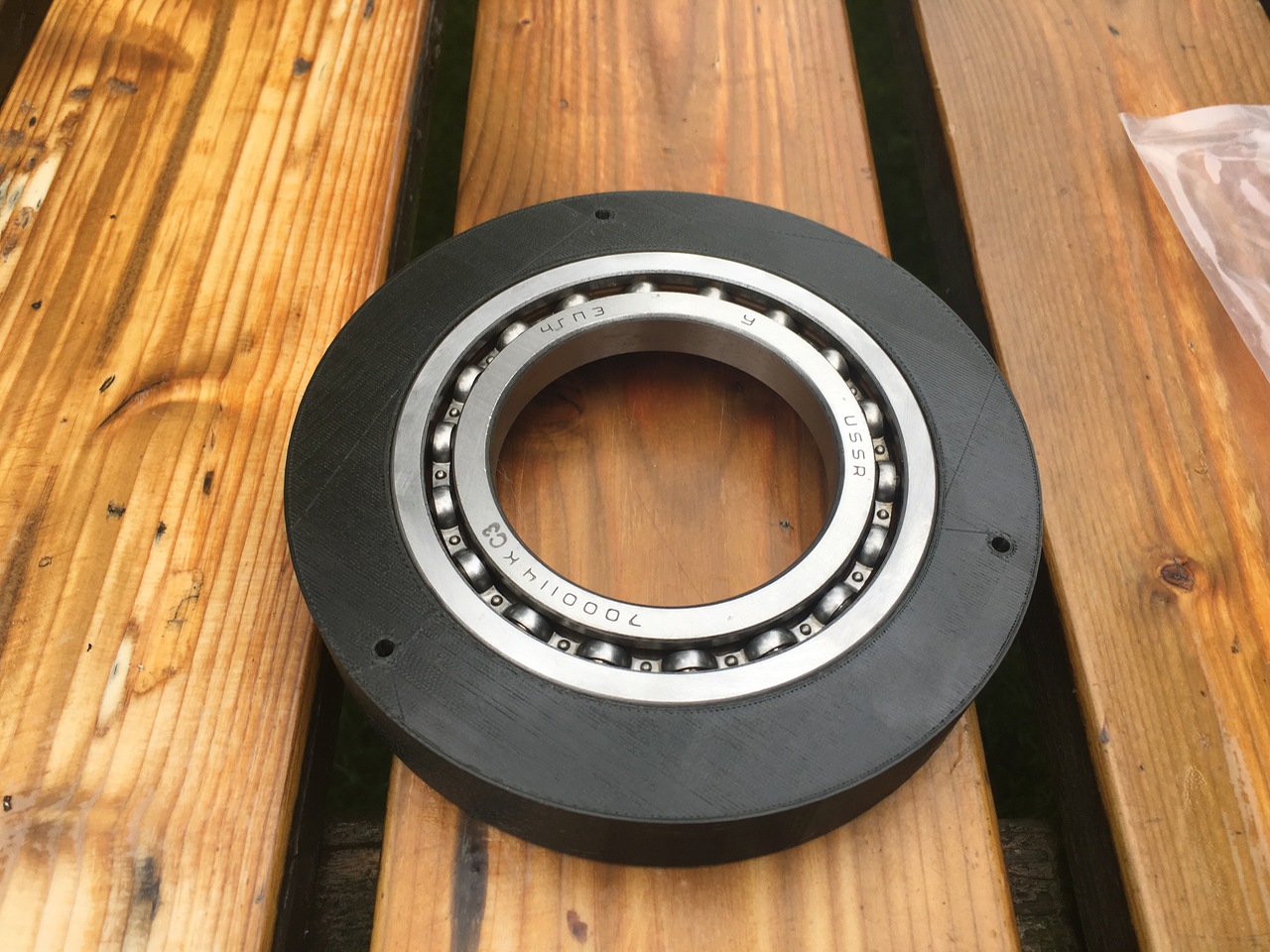
08/16/2017 at 13:53 • 7 commentsYesterday the bearing 16014 arrived from eBay. It did cost $14.04 shipping included. It's a russian bearing. The quality is very good.
![]()
![]()
![]()
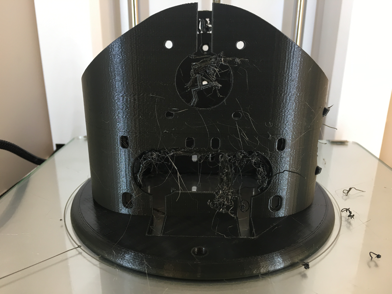
Tonight the printer printed ART1BODY_P2.stl. This morning I found out that one of the very thin walls had collapsed. But after cleaning the print it is nice enough to be used.
![]()
I created the supports with Meshmixer. They look nice. I have some trouble printing thin lines (like the support structure in Cura) with PETG filament. Cura doesn't have a setting for this material type. I use the CPE profile.
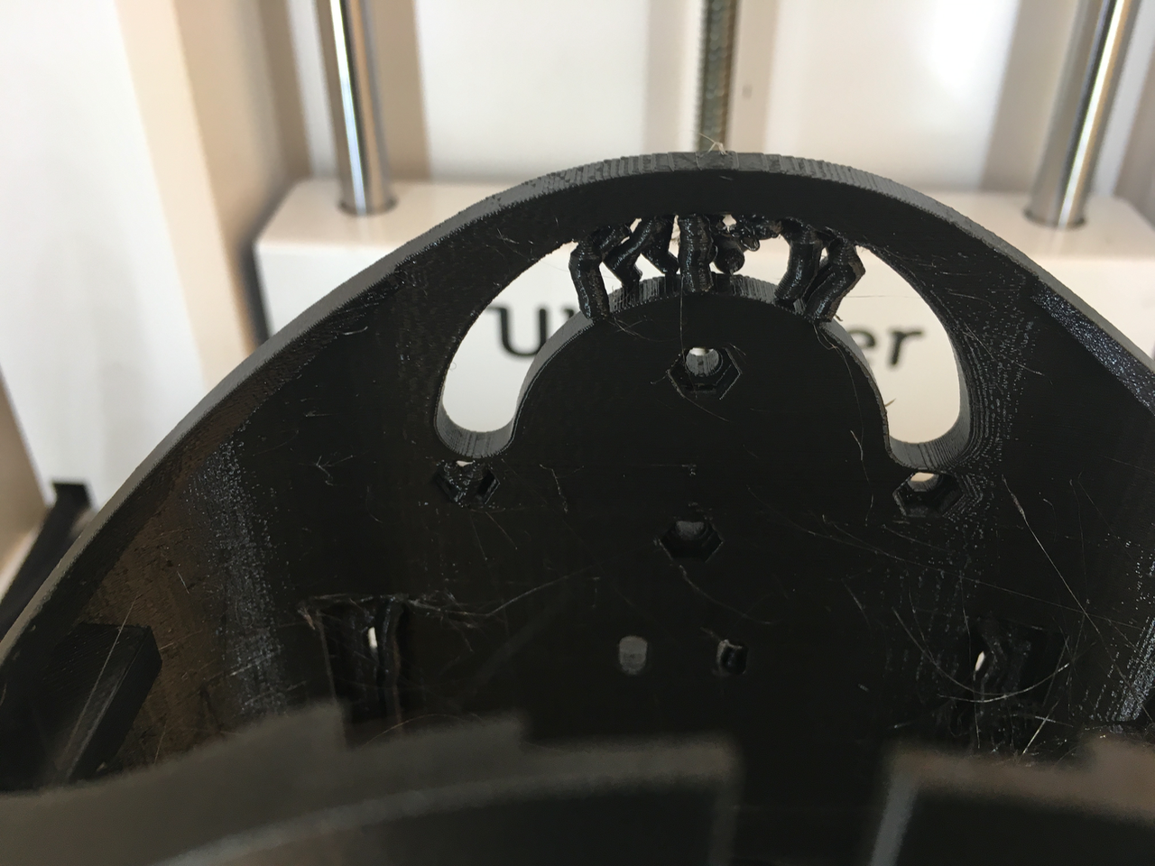
By using Meshmixer support I could create another type of support structure. This looks very nice, doesn't cost much material and is easy to remove.
![]()
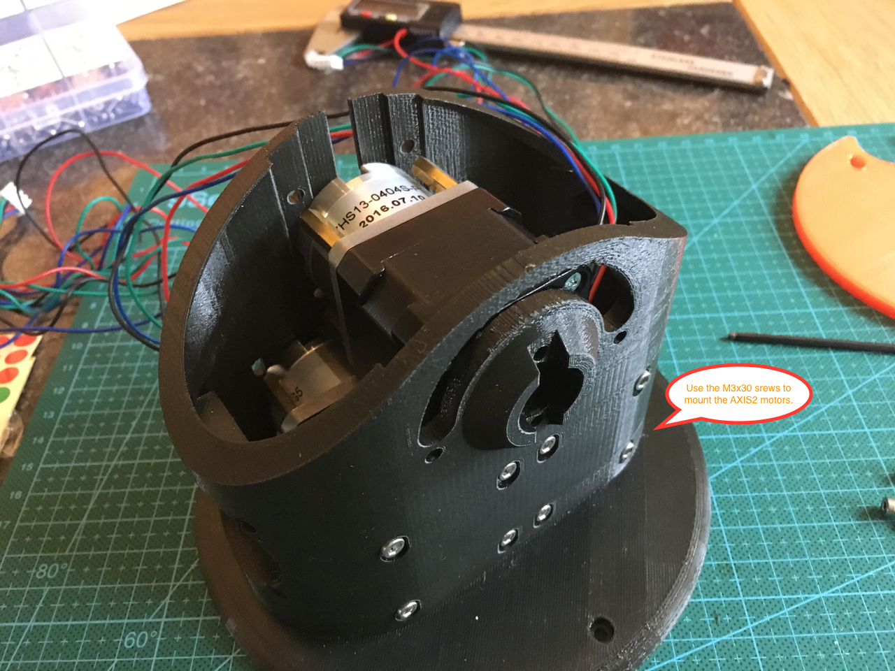
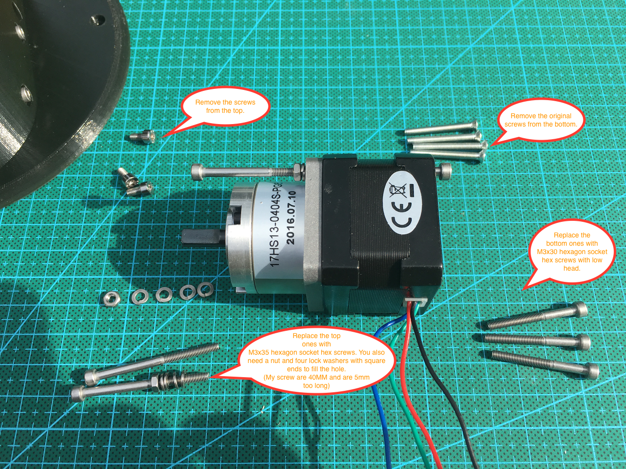
After cleaning this part I was ready to temporarily mount the stepper motors.
First I had to remove the screws from the stepper motors and then I replaced them with M3x30 and M3x35. I didn't have M3x35 so my top screws are too long and will be replaced tomorrow.
UPDATE: Please look at day 7 for a better and easier way to mount the motors.
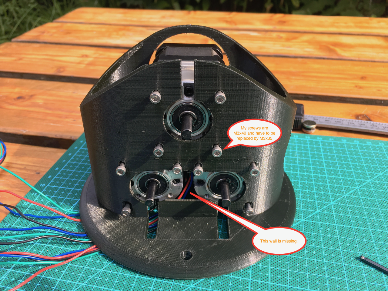
![]()
![]()
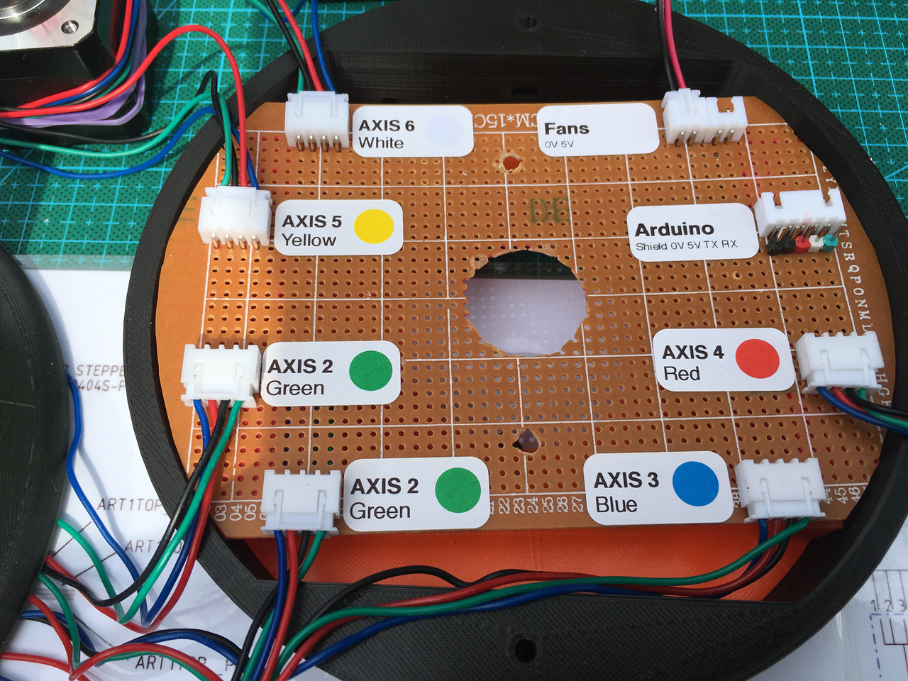
After mounting the motors it was time to create the custom PCB with the connectors. An 24 wire slipping will be added in the future.
![]()
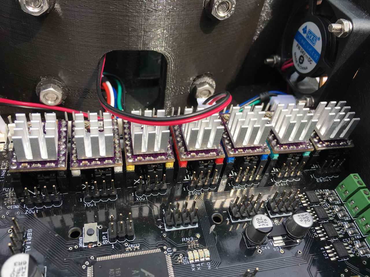
The wires will get some color codes. The polulu stepper motor driver male header pins have the same colors. (So the red coded wire will be inserted in the red connector and will be driven by the red polulu).
![]()
The two green connector pins are connected on the underside of the PCB. The 0V and 5V from the Arduino connector are connected to the Fan connectors. The male header pins below the Arduino connector can be used for debugging purposes.
![]()
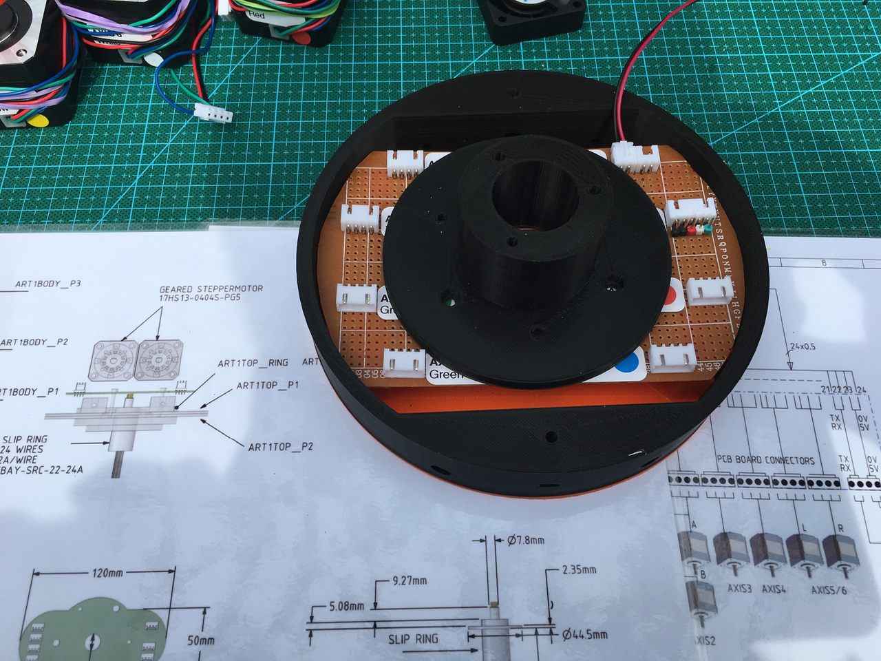
Make sure you leave some room for the ring that will be mounted on the underside of the PCB.
![]()
The PCB is mounted on the ring with some distance between them (to make room for the slip ring and its wires).
![]()
![]()
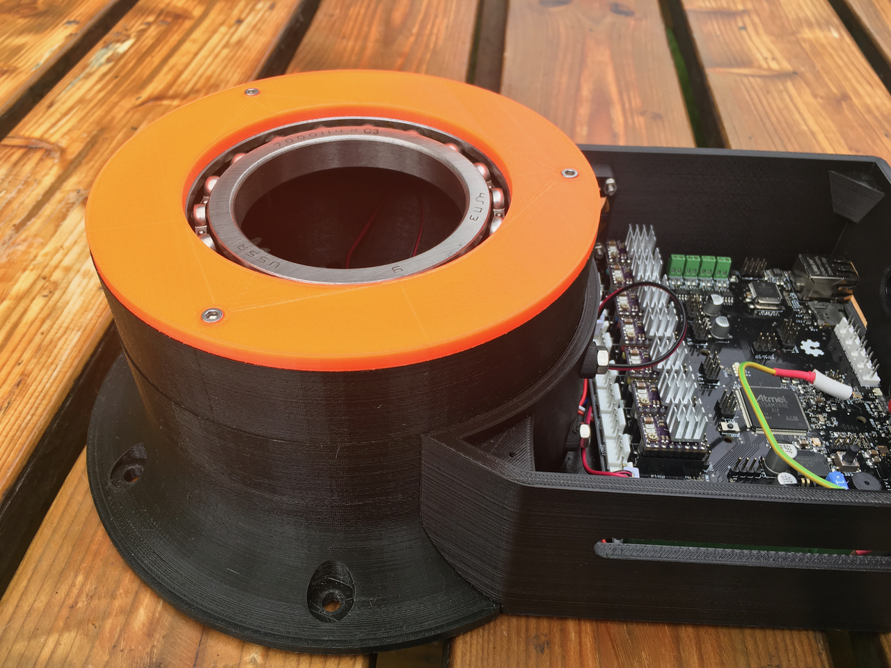
Axis 1 can be fitted on or removed from the base.
![]()
![]()
-
Day 5: Powering the electronics
08/15/2017 at 08:00 • 4 commentsYesterday Olaf Baeyens gave me some good advice about adding an emergency switch. "Something that may be important to your electronics. In my situation I originally cut the power at the mains voltage. However I pretty fast discovered that the main power supply holds a lot of more energy so the stepper motors did not immediately cut their movement. Especially when you develop your software this can destroy your parts or even worse lose a finger."
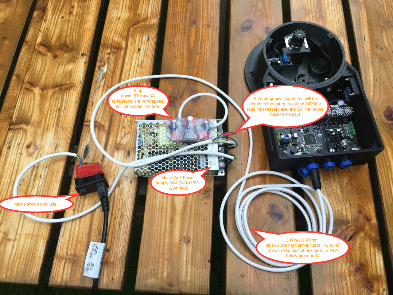
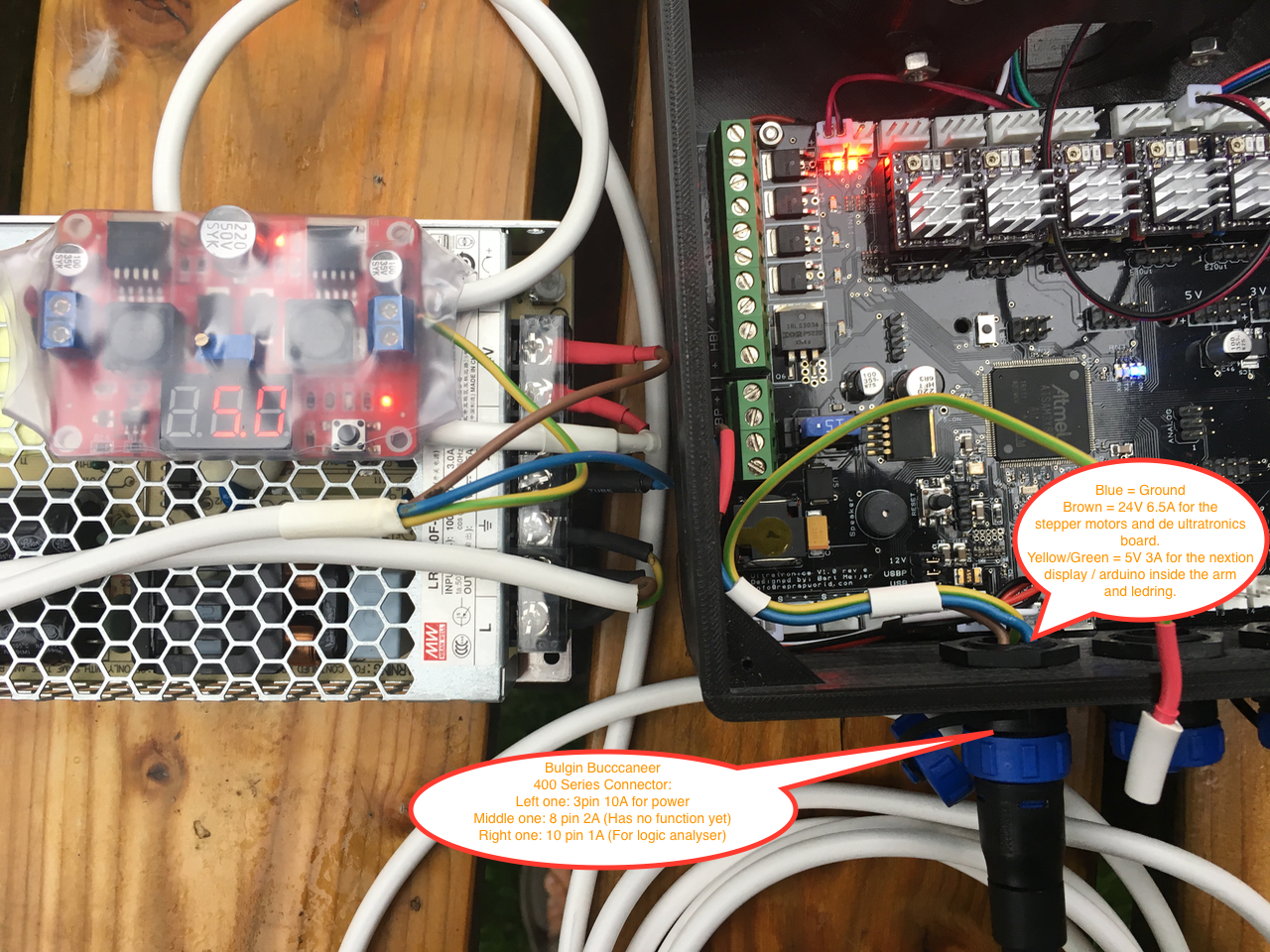
So I have ordered one today. Below two photo's of my setup. I'am going to created an case for the Power supply and Step down converter. This case will also contain the emergency button to cut the 24V line so that all the stepper motors will stop immediately.
This case will provide power though a thick 3 core wire to the base (Ground/24V/5V). If necessary I could also cut the 5V line for the Nextion Display but I don't expect that to be necessary.
The Ultratronics can be powered by the 24V input, or by both USB ports. Is it safe to connect the computer to one or both USB ports and use the 24V input at the same time? Or do I have to change one of the 3 power input jumpers? Momentarily I'am using an USB isolator to be safe.
![]()
![]()
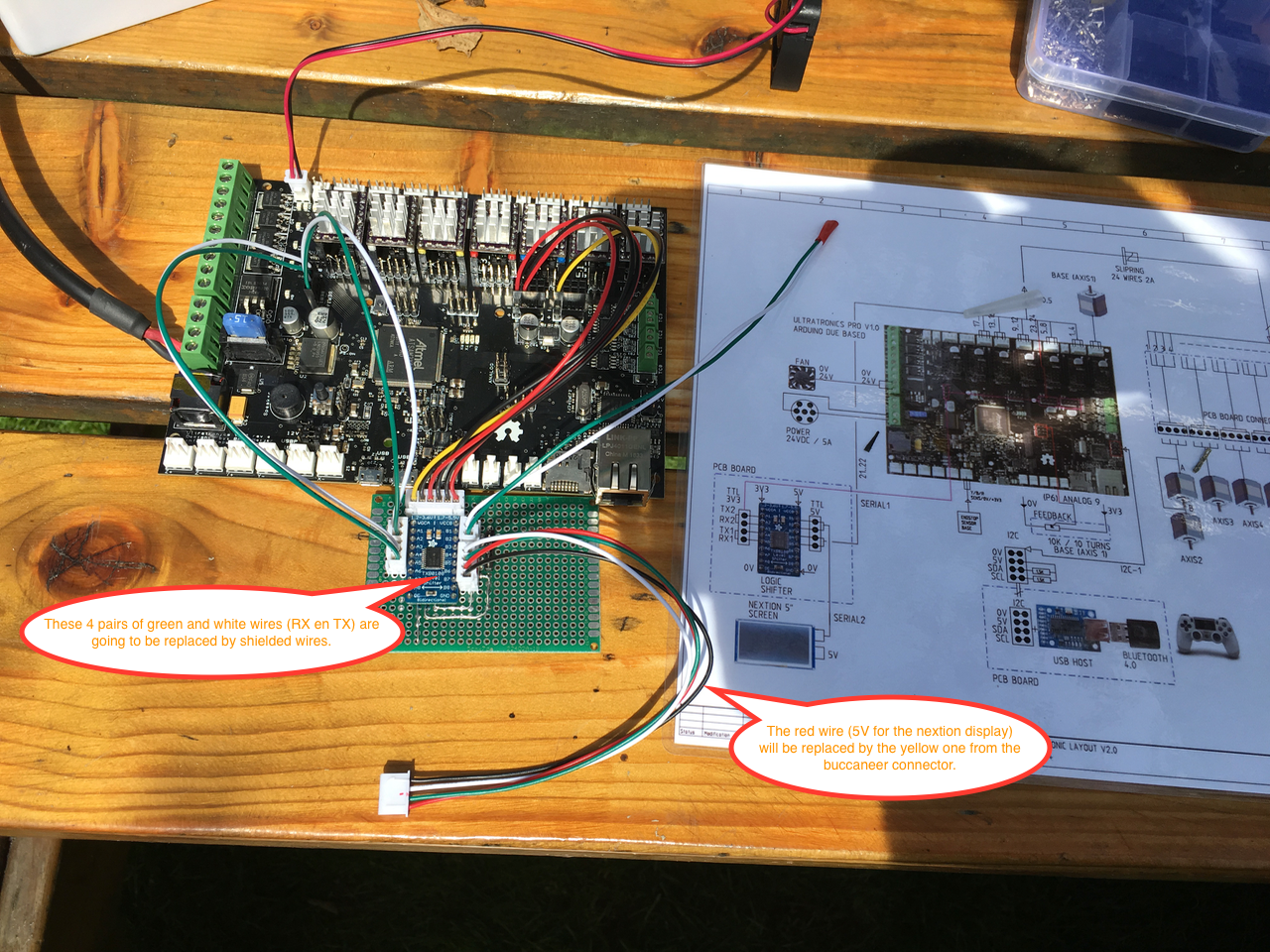
Danny gave some good advice about using shielded wires for the RX en TX to prevent electrical interference. "Your nextion serial connection between the serial port on the ultraboard needs to be shielded! That solved all my communication problem I had in the past."
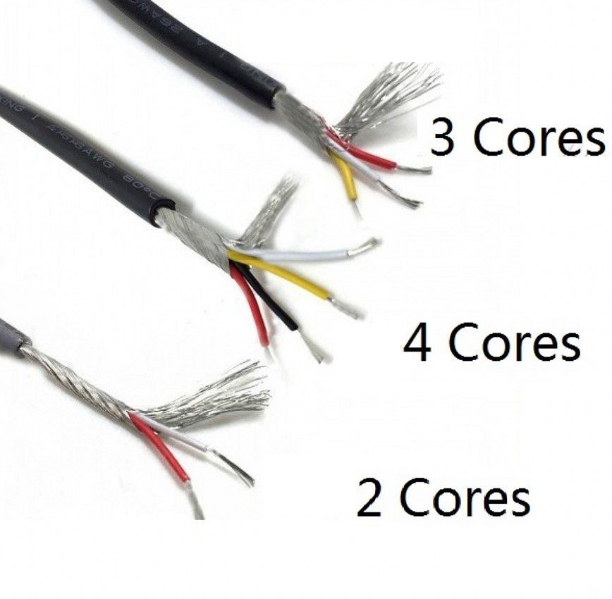
I have ordered 24 awg 2 and 3 core and 26 awg 4 core shielded (headphone) cables.
What is the best way to shield the cable? Some people say that you don't have to connect the shield. Some people use the shield as ground. And some people are connecting the shield on one side to ground.
![]()
![]()
-
Day 4: Adding some extra parts to the base
08/13/2017 at 09:46 • 0 commentsMy robot arm will be using the black an fluor orange colouring scheme. The stepper motors are mounted in the black parts. Those parts can get to hot for PLA (max 60°C). PETG can handle 80°C and should be easier to print then ABS. PETG has no shrinkage and no bad smell.
I will try to print all of them in PETG. But I'am having a little bit of trouble printing the support in PETG. It sticks to the print head. I'am also going to change and reprint the base because I want to add a fan inside.
![]()
![]()
Building and improving the Thor+ robot arm
Building a 6-axis robot arm based on the AngelLM's Thor robot and the add-on's and improvements of dannyvandenheuvel.