Shah Selbe
-
Designing Upper, and the dreaded 'Swamp Finger'
07/29/2019 at 21:07 • 2 comments![]()
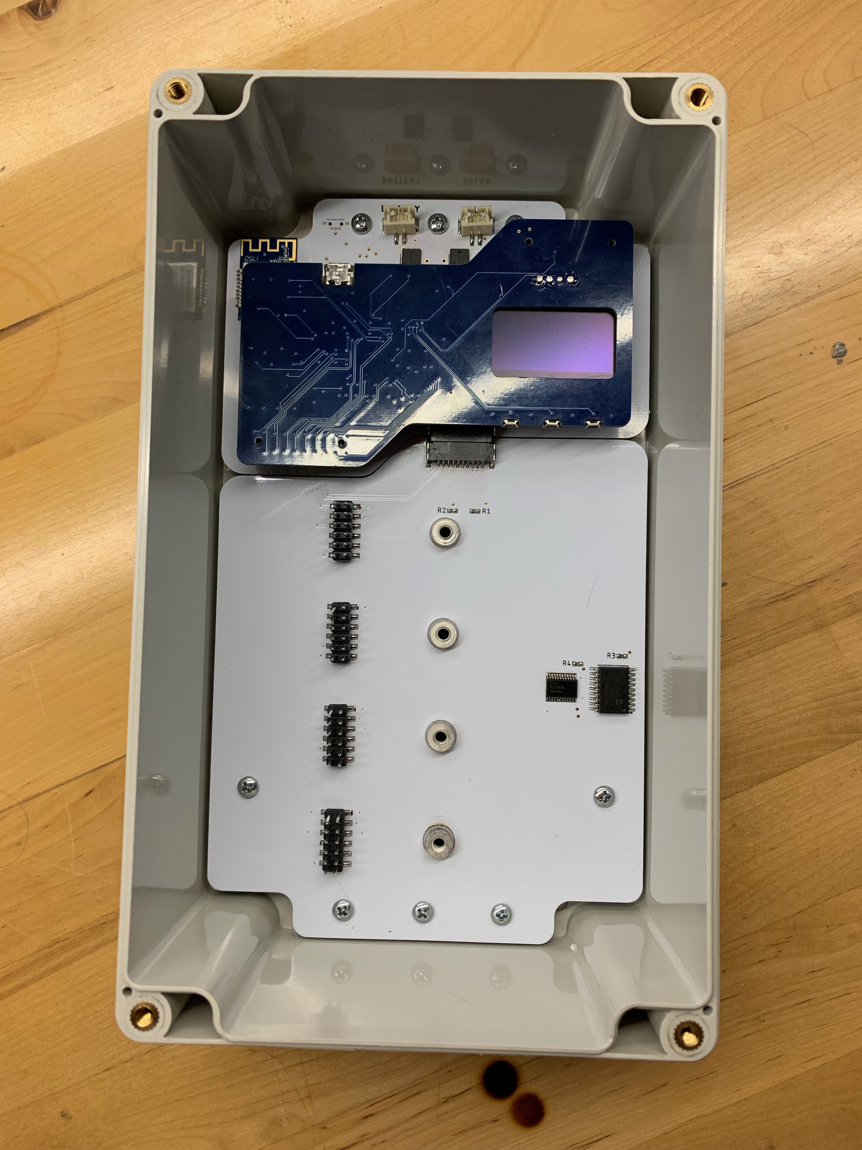
With a general architecture established, Upper seemed like the obvious choice for a first build. One of the first things to think about was Swamp Finger.
![]()
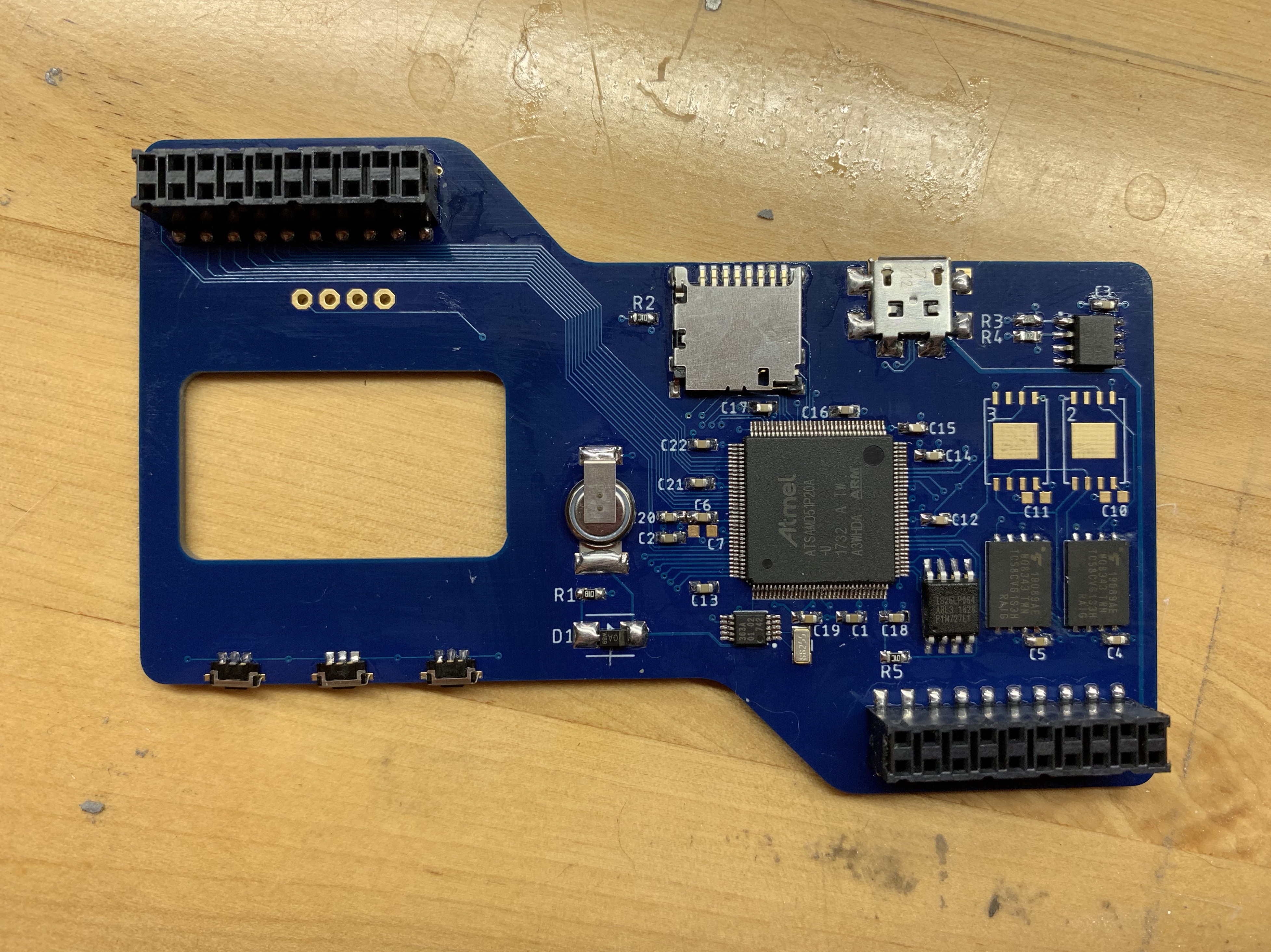
FieldKit stations go to unfriendly places. They typically live in water-resistant enclosures, but when those enclosures do get opened, the conditions may well be less than ideal. The hand reaching in, to probe at the delicate electronic guts may well be dirty, wet, or clumsy. Jacob coined the term "swamp finger" to describe the hazards of living in these environments. This immediately ruled out otherwise attractive options like capacitive sense 'buttons', but it also led to one of the more striking design decisions of the process, which was to place components only on the inside of the sandwich made by Upper and Lower, where no swamp finger is apt to roam.
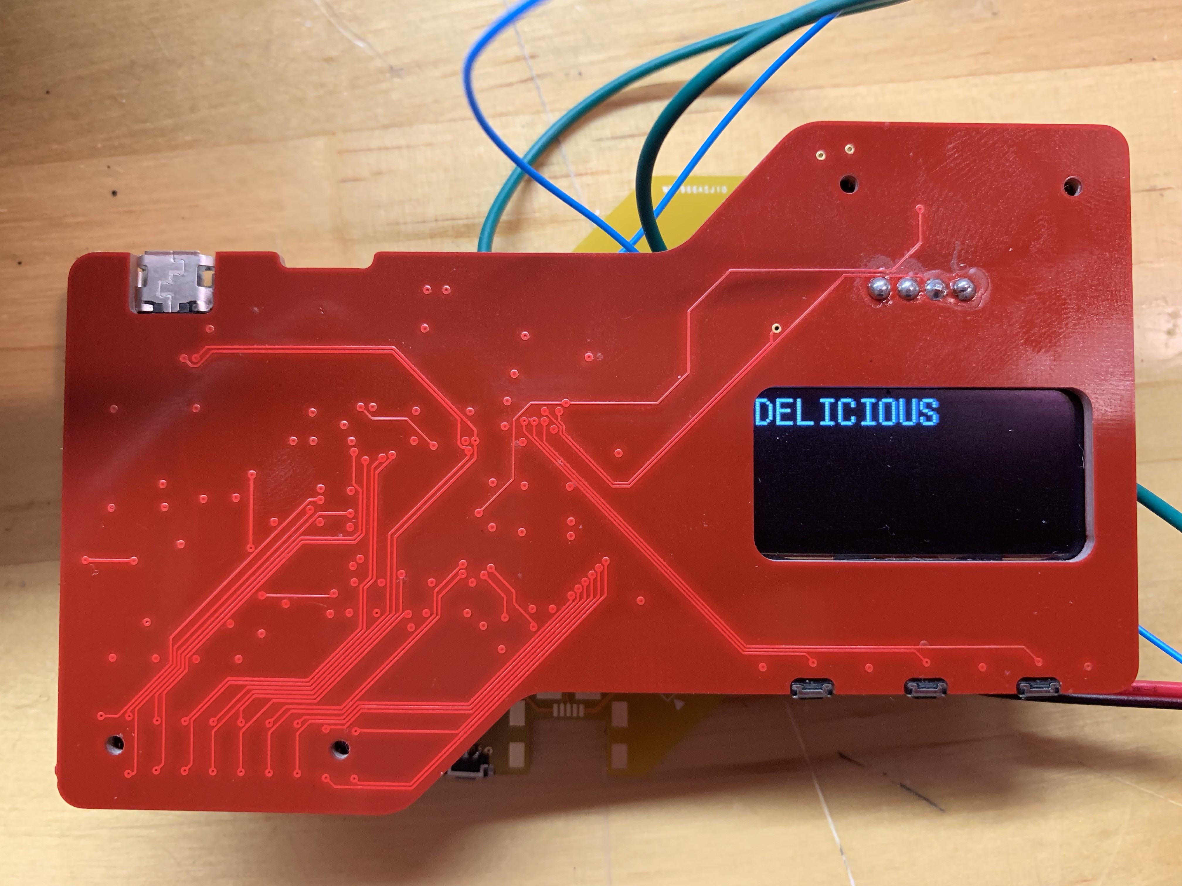
This somewhat complicated our desire to add a screen. Previous FieldKit hardware attempted to indicate all needful data with LEDs. This is not ideal in the field, or for that matter, for battery consumption, so the plan was to go with one of the ubiquitous I2C OLED displays which have been in so many projects in the last few years. Since we were only populating the invisible side of the board, this meant reverse-mounting the OLED display and cutting a window in the PCB so that it could be seen from the other side.
![]()
Then it was just a question of choosing the right tools for the job :
Storage
Once upon a time, we relied entirely on the SD card for storing the data gathered by FieldKit stations when deployed. The price is right, but as anybody involved in #badgelife can tell you, SD cards are The Worst and probably not to be trusted for mission-critical jobs of that kind. Darwin needed on-board memory, so we put in four slots for high capacity SPI NAND flash. We typically use 2Gb chips, giving us a 2-8Gb installed range, depending upon need. The SD card is now for backup and contingency offload if the radios fail.Microcontroller
The ubiquitous ATSAMD21 series had served us well, but we were entirely saturated for pins and memory. That said, we didn't want to leave the Atmega Cortex line entirely, as community support for and understanding of the chips is very good, so we ended up with the biggest of the line, the ATSAMD51 in a 128 pin TQFP package. Bring me all your pins and RAM!In support of the ATSAMD51 we installed a fairly hefty QSPI flash chip for bootloader duties.
RTC
In theory, we could have used the internal RTC on the ATSAMD51 for RTC duties, but prior experience made me slightly gunshy on that point, so we used an external RTC, and supplied a supercapacitor to serve as its 'battery' backup. Previously, we've used CR2032 cels for this, but the irony of making a conservation-oriented product with primary lithium batteries struck us as a little hard to justify. Since this RTC also had clock out, we used it to pump a clock into the microcontroller and only needed the one crystal.MISC
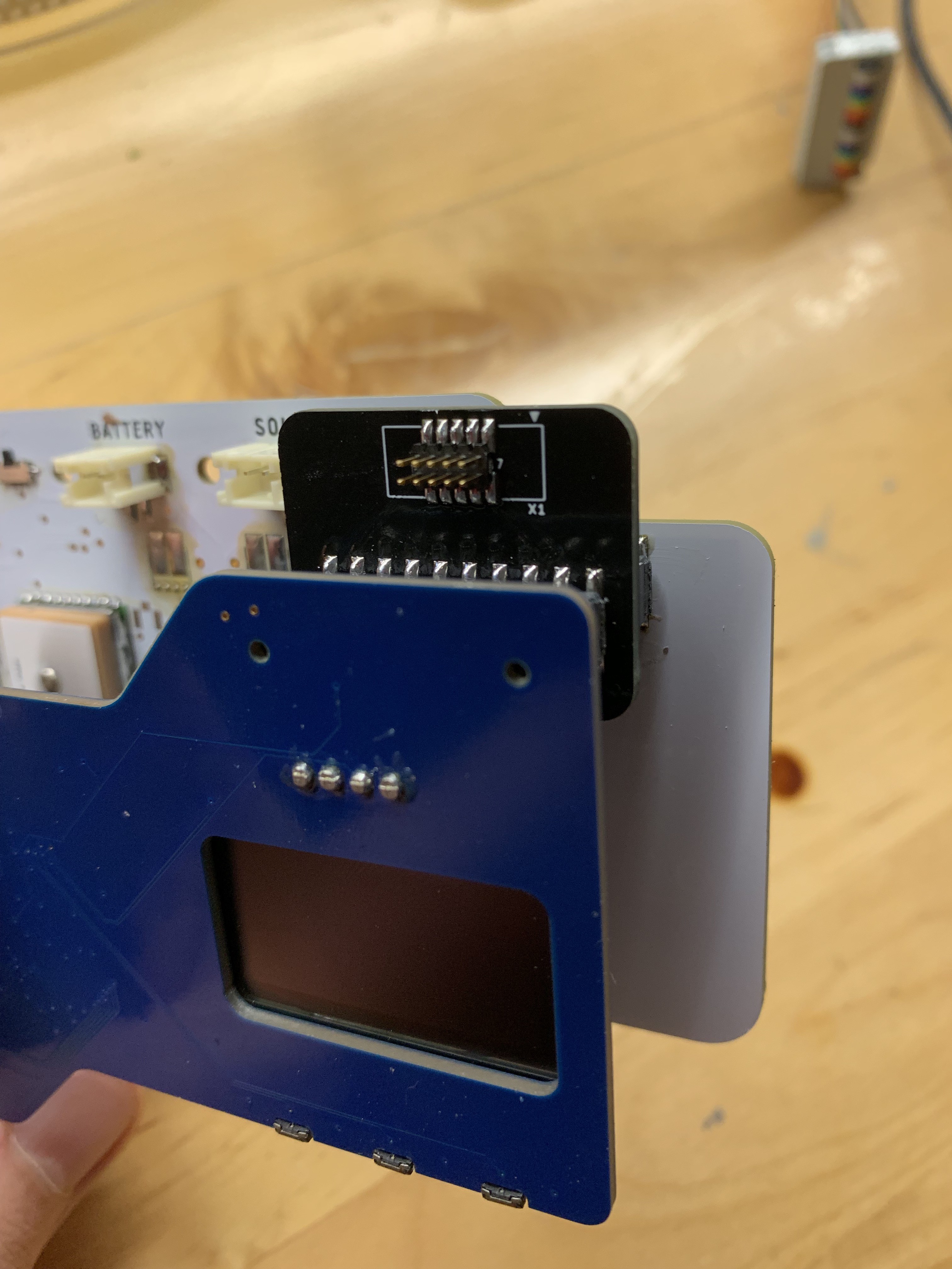
2.54mm pitch box headers seemed like a natural choice for mezzanine connections between Upper and Radio. They are ubiquitous, durable, and tall (the GPS module is a big boy).
What about a programming header? Well, we decided not to have one. All the pins required for programming are on the mezzanine connector. Batch-programming jigs were always in the roadmap anyway, and for in-circuit debugging, well, Jigs Ahoy!
![]()
In the interest of monitoring and predicting battery life in cold conditions, we added an inexpensive temperature sensor as well. Thought it looked cute, might delete later.
Next up : Radio!
-
Identify Yourself, Firmware!
07/29/2019 at 20:36 • 0 commentsIt all began with a common firmware header. This header is at the beginning of every binary our build system produces and contains metadata about that particular binary. Information like the timestamp of the build, the hash of the binary, the git commit of the source tree, the binary’s size and, critically, symbol information.
There's a few ways to do this. The quick and dirty way is just to concatenate the header and the generated binary. This approach would work but also leaves a little to be desired, especially when compared to "The Right Way". In this situation, the right way is to include that firmware header as an actual symbol declared in the source and to carry it through the entire build process. So this means I got to spend a lot of time learning about linking and linking scripts.
Linking in modern C/C++ is incredibly complex and so this project was a good introduction to prepare myself for future functionality and this is by no means an exhaustive description of that process. Our build chain looks something like this:
- Compile *.c, *.cpp, and *.s to object files.
- Archive grouped source files into static libraries.
- Link those libraries together to form an ELF file.
- Run that ELF file through a custom tool [1], generating an “FKB-ELF” file (FKB is FK Binary)
- Developers can then use that generated ELF with gdb or dump a binary using objdump.
To get our headers working, it all starts with a declaration.
Typically, the very first chunk of data in your firmware binary (for a Cortex-M chip) is the ISR vectors table. This table starts with the initial stack pointer value, and then a table of pointers to the functions for handling various IRQs. This is where the hardware finds your
Reset_Handlerfunction, which is the first function to be invoked.Executable files are composed of multiple sections, or segments. Each of these has a special purpose. For example, executable instructions are stored in
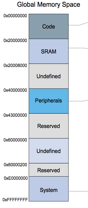
.textsegments. If you refer back to the post on Memory, data is stored in a.datasegment, and there's also a.bsssegment, though it's not present in the binary and just managed so that we can determine its size. In all major compilers you can override the section/segment that variables and functions are kept in.What I wanted was for the FKB header to occupy the leading bytes of the final binary, before the vectors table so that the bootloader and other tools could find them. This is very easily done by assigning variables to custom sections in the source, in my case using gcc’s
__attribute__((section()))mechanism. So, the header is declared like so:__attribute__((section(".fkb.header"))) const fkb_header_t fkb_header = { .signature = FKB_HEADER_SIGNATURE(), .version = 1, .size = sizeof(fkb_header_t), /* Etc */ };The linker script then places this section before the ISR vectors, being sure to maintain the alignment the hardware expects on that table.
.data.fkb.header : {
    KEEP(*(.fkb.header)) . = ALIGN(0x1000);
} > FLASH
I should mention that the header as compiled is basically empty and filled with default values. I wanted to be able to customize this header after compilation. Especially because certain things become tricky if you try to inline the header values during compilation, like how do you include the hash for the final binary? Catch-22 town. I also knew that there would be other steps that would have to be performed after linking, which we’ll get to later.
Next, enter our custom firmware tool. I wrote this tool in Python using the libraries provided by the LIEF project [2] This is a library for manipulating ELF files and has been great. With this library it was very easy to open up the fresh ELF file, find the section I was looking for and replace the contents with the final header, with all values populated. Because this happens after linking the tool has access to all kinds of information it might not otherwise know, like code and data section sizes and the final size of the binary. A new ELF file is then generated and the header appears at the start of the binary as expected.
Our bootloader knows to look for these headers when loading firmware. It can tell if there’s a header using a magic string. If that header is missing it'll just boot the binary as regular firmware. Otherwise, the bootloader can find the vector table using an offset baked into our header so that future headers can be sized arbitrarily. Our bootloader also reports this information to the debugging console:
bl: looking for executable...
bl: [0x00004000] checking for header
bl: [0x00004000] found ('fk-bundled-fkb.elf_JACOB-HOME_20190726_155624') flags=0x0 size=161424 vtor=0x1000
bl: [0x00004000] hash='884b434ee60e8d38bad81ae5d3e48c07acadfdd2' timestamp=1564156584
bl: [0x00004000] number-syms=0 number-rels=0 got=0x0 data=0x2000048c
bl: [0x0002C000] checking for header
bl: [0x00005000] executing (entry=0x00005004) (got=0x20000000)
There’s some other information in there that I’ll get to later. This information can also easily be included in diagnostic reports and compared to binaries on phones or provided over a network. It’s also alerted me once to a situation where I broke our build system and wasn’t getting new binaries!
[1] https://github.com/jlewallen/loading/blob/master/tools/mkfirmware.py
-
Increasing Camera Trap Efficiency with Machine Learning
07/29/2019 at 17:43 • 0 comments![]()
BBC Wildlife Camera-trap Photo of the Year 2014 As machine learning becomes more and more ubiquitous, the development of smart devices and IoT that’s “on the edge” should become dramatically easier. Given this, I was interested in exploring applications for machine learning in conservation biology, specifically in animal recognition for camera trap images.
Camera traps, used by environmentalists, filmmakers, and researchers, are deployed into the wild to monitor animals. Triggered by infrared sensors, camera traps can detect movement and autonomously capture photos and videos of animals. This is a boon and curse for environmental monitoring because image results can vary widely, ranging from false positives to shots worthy National Geographic. Similarly, researchers may collect an overabundance image data or none at all. The variability in camera trap results makes image processing and deployment management an incredibly tedious process.
Using object detection and image classification models, we can make animal monitoring much more efficient. The range of efficiency, however, depends on how machine learning is applied. In this article, I will provide a brief introduction into two possible avenues to explore.
But before jumping in, I would like to first cover the limitations of machine learning for image processing. While it would be immensely convenient to use machine learning to identify species all over the world, there are simply too many species for one model to cover. The most practical application of machine learning would be to build an object detection model to identify the presence of animals in an image, and then complement the object detection model with a regional, geographically-specific image classification model. The results of object detection models for animals have been proven to be quite robust, reducing the time spent sifting through false positives. Furthermore, image classification models trained on smaller subsets of animals have also provided accurate results.
So, the first and most straightforward method of increasing animal recognition efficiency is to simply run camera trap images into an object detection and image classification model once all images are collected. In my time perusing the internet for available models, I found an open-sourced animal object detection model run on InceptionNet that was built by Microsoft’s AI for Earth project.
Unfortunately, I was unable to find any open sourced image classification models because of its lack of generalizability. There have been multiple research efforts examining the accuracy of animal classification, and results have shown that a model trained for a specific location will perform significantly worse when applied to a new geographic region. An example may be found here.
Most models were built to research image classification accuracy, trained for specific locations such as the American Midwest. When applied to a new location, image classification accuracy decreases significantly. If you are interested in training your own image classification model, you may find valuable datasets in Lila Science, a library for environment-related datasets. I would recommend using the datasets, Caltech Camera Traps or Snapshot Serengeti.
The second and more ambitious method is to build a camera trap “on the edge.” There are currently no camera traps that offer on-device machine learning, but it is quite easy to build a nascent one using accessible hardware.
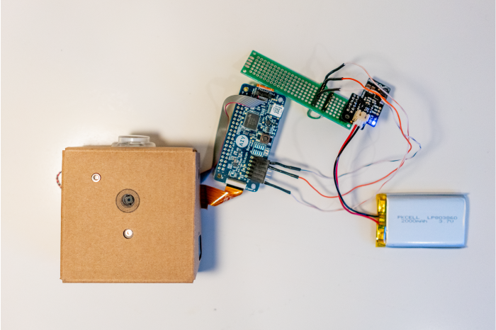
![]()
To test this possibility, I simply hacked a Google AIY vision kit, which comes with a Raspberry Pi, Vision Bonnet (Google’s ML processing board), Pi Camera, and other hardware pieces to tie it all together. To make it a real camera trap, I added my own PIR sensor that would trigger the camera to take an image and process it with a model.
On the software side, there were already a number of built in TensorFlow models that were fun to play with but not all that useful for building a camera trap to recognize animals. Nonetheless, I used TensorFlow’s image classification model to build a simple prototype and test functionality within the Conservify lab. To really build robust machine learning models “on the edge,” you can retrain the TensorFlow object detection model using SSD MobileNet with the same database that was used to build Microsoft’s model. Tutorials to learn how to retrain TensorFlow models are also available on Tensorflow's website.
Beyond machine learning, there is also a big space for technology that allows for real time updates using tools like LoRa or cellular connection. Real time updates could help reduce the duration in which camera traps are deployed in the wild by notifying users when images have been taken. We at Conservify are currently experimenting with various types of communication hardware to tackle this problem. We’ll hopefully provide an article on this soon. In the meantime, have fun exploring! There is so much potential for innovation in the space of animal recognition and camera traps.
-
Designing a User Experience that’s Accessible to All
07/29/2019 at 17:33 • 0 commentsThe Problem
The current assortment of available scientific tools for environmental monitoring, field science, and data-driven storytelling is too expensive, unnecessarily proprietary, and not user friendly.
At FieldKit, we want to create an environmental monitoring platform that’s accessible to everyone – that is, low cost and available to experts and amateurs alike. The FieldKit app plays a critical role in setting up the physical environmental sensors. These two elements have to feel like complementary parts of the same overall FieldKit experience. Our goal is to create a seamless hardware-app experience that is engaging and reassuring for all our users.
The Design Process
To create a seamless user experience, we followed the design-thinking process of user and landscape research, problem definition, and solution design and testing through iterative prototyping:
User Interviews: Empathize and understand users’ needs and pain points
Competitive Landscape Research: Research of the environmental monitoring industry
Designing and Prototyping: Creating the user flow, wireframes, and prototypes
User Interviews
To better understand what features would be useful in the software, we first had to understand the users. Who are our users, and what were their current behaviors, needs, and concerns? How might our findings help us design an experience that brings them value?
FieldKit User Personas
Field Scientists
Graduate Students
Educators
Citizen Scientists
Activists
![]()
Overall, we conducted 18 user interviews from a variety of target user types – field scientists, educators, citizen scientists, and environmental justice advocates. During the interviewing process we discovered that generally these roles interact with FieldKit at different levels – either as a data collector, a data author, or a data consumer. For example, we learned that field scientists were not actually going to out into the field to deploy sensors and collect data, the graduate students were doing that. The field scientists were the data authors, setting up the project parameters for Graduate Students (data collectors). This discovery focused our efforts to subsequently interview graduate students in order to create a new persona and gain further insight.
We found that the 5 different user personas that had unique behaviors, all had similar needs. The main concerns were easy to use and easy to visualize the data. We took user feedback a step further by collecting data through an online survey. The survey included questions about their role, what sensors are most interesting, and what features were important.
We gained the following insights from the online survey:
- Water quality and air quality were the top sensor types
- An active online community was the top software feature
- Easy setup for non-experts and easy data sharing were the came in 2nd and 3rd place for software related features
Competitive Research & Journey Mapping
Understanding the current environmental monitoring product landscape was an important step in defining FieldKit’s unique value proposition and informing the user experience design. What were the available products out there? What were their limitations, and how might that understanding reveal opportunities for the FieldKit experience?
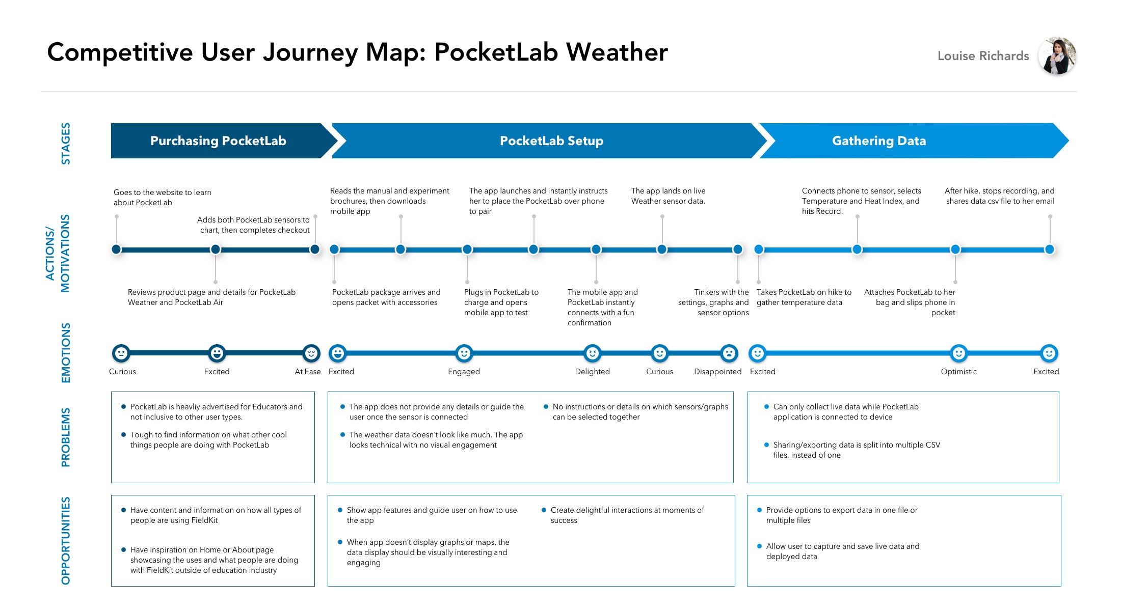
Although there were a number of consumer products on the market, it was tough to find a direct competitor that offered the type of scientific grade environmental sensors and easy-to-use user experience that we’re aiming for with FieldKit. It thus benefited us to look beyond the environmental monitoring space at adjacent markets. There was one that seemed closely related; PocketLab is an educational product that pairs a variety of sensors with a mobile app and website. We used them as a research case study, and created a competitive user journey map.
![]()
Opportunities from Competitor Research
We gained the following insights for designing the FieldKit experience:
- Set expectations early on for calibration steps and make sure the process feels simple and short
- Show app features and guides on how to use before instructing user to connect sensor
- Providing multiple file export options
- Create delightful interactions at moments of success
- Guides/tutorials throughout the app
Designing and Prototyping
After gathering user needs and conducting competitive research, we had a better understanding of how to optimize the app experience. Balancing user and business needs, we defined the ideal FieldKit experience. We created user flows, sketches, and wireframes to develop the mobile app that configures the sensor hardware.
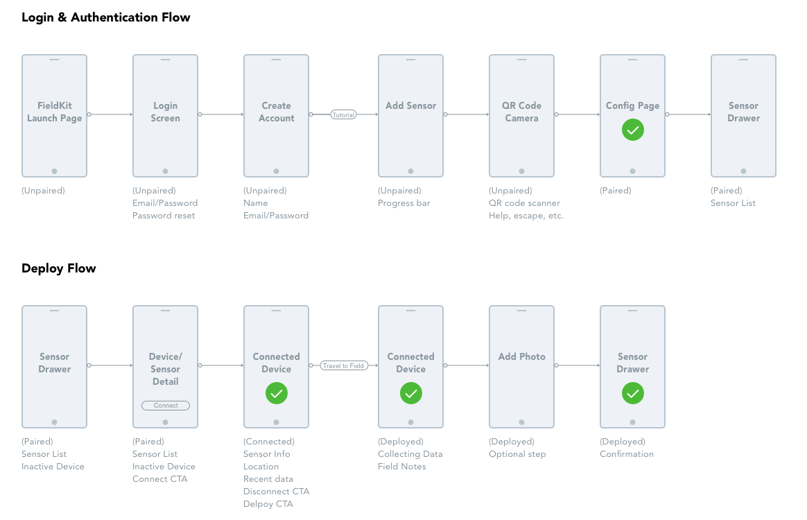
The team came together in a white boarding session and created user flows for Login and Authentication, as well as station Station Set-up and Deployment. Laying out user flows allowed us to generate a list of tasks that took place at each step, and to strategize about the features that would best facilitate those tasks and create maximum value.
![]()
During the wireframing process, the challenge was communicating clearly the information from the FieldKit station without overwhelming the user. With every detail – battery level, available memory, the latest data readings, or error notifications, we asked ourselves, is the interaction simple enough for a 3rd grade science class? Are these features robust enough for the field scientist?
Another important factor was designing the deployment flow for when a user is out in the field. How should the app look and function when the user has access to a network? We thought it helpful to show their location with a map. Alternatively, if the user is in a remote location without network access, we simplified this user interface by using GPS to display coordinates.
After a few iterations we landed with a really cool prototype that is ready for user testing! Once you have a solid prototype design, it is extremely important to understand how users interact with the app and improve the design. The user experience design process is a continuous cycle to create the best product for users.
![]()
-
Origin of Species: Darwin
07/28/2019 at 18:01 • 0 comments![]()
If you've ever learned a new skill by doing, you're familiar with the experience of working your way through a project to completion only to immediately want to start over with all the understanding you've gained in the process. Building hardware and deploying it for scientific fieldwork is a very similar crucible. The process of building and assembling tens of remote instrumentation stations will tell you where the unexpected time sinks and pain points are. Deploying them will reveal where the hardware is fragile, inconvenient, or counterintuitive. All the while, you'll be coming up with features you wish it had.
When I joined the FieldKit project, the general shape of our future hardware was already starting to emerge through this process. Essential as it was, the current hardware couldn't take the project where it needed to go. A new generation of hardware was going to be required, and since you should never miss an opportunity to give a project a good internal code name which makes you feel like a secret agent, I dubbed this next step in FieldKit evolution 'Darwin.'
Architecture
![]()
Up until Darwin, a Fieldkit station typically consisted of two boards. The "Core" board handled radio communication, GPS, data logging, and power management. The Module handled tending the sensors, whatever they were in a given situation.
So, in an ideal world, what do we want?
- Fewer cables.
- Multiple modules per station (Ideally several different possible configurations, without wasting a lot of space).
- Fewer duplications of expensive and power-hungry microcontrollers.
- Separation of the radios (where our needs are diverse and fast-evolving) from the data logging bits (which are not).
- Easier manufacture and assembly.
- A rudimentary graphical display.
- Standardized module pin-out and footprint.
It might be useful to point out that our goal has never been to hit big venture capital, and have 20,000 units of Fieldkit produced in China for a few bucks apiece, so the pressures that cause many an engineer to condense everything into a single compact board for easy mass production don't really apply here. That said, starting to break the FieldKit system into separate PCBs does actually improve the manufacturing equation by turning the slowest evolving part of the system into something which can be produced by contract manufacture in larger quantities, without committing us to producing large numbers of those parts of the system which evolve faster. I'll be writing more on our manufacturing philosophy later.
So, if you work your way through this list assuming that you're going to end up with several boards and connect them with board-to-board means rather than cables, you end up with an architecture that looks more like this :
![]()
Now in an ideal world, Power Management, which is always basically the same, might have ended up on the Upper board, but there were good mechanical engineering reasons not to go that way. (Curse you Meatspace, ruining my fantastic theoretical diagrams!)
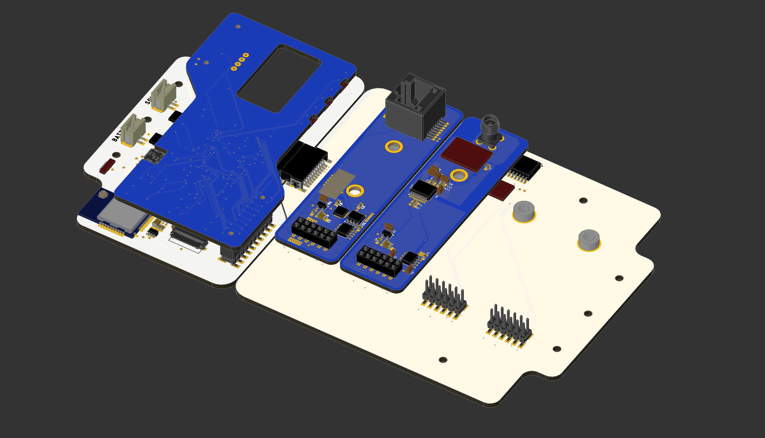
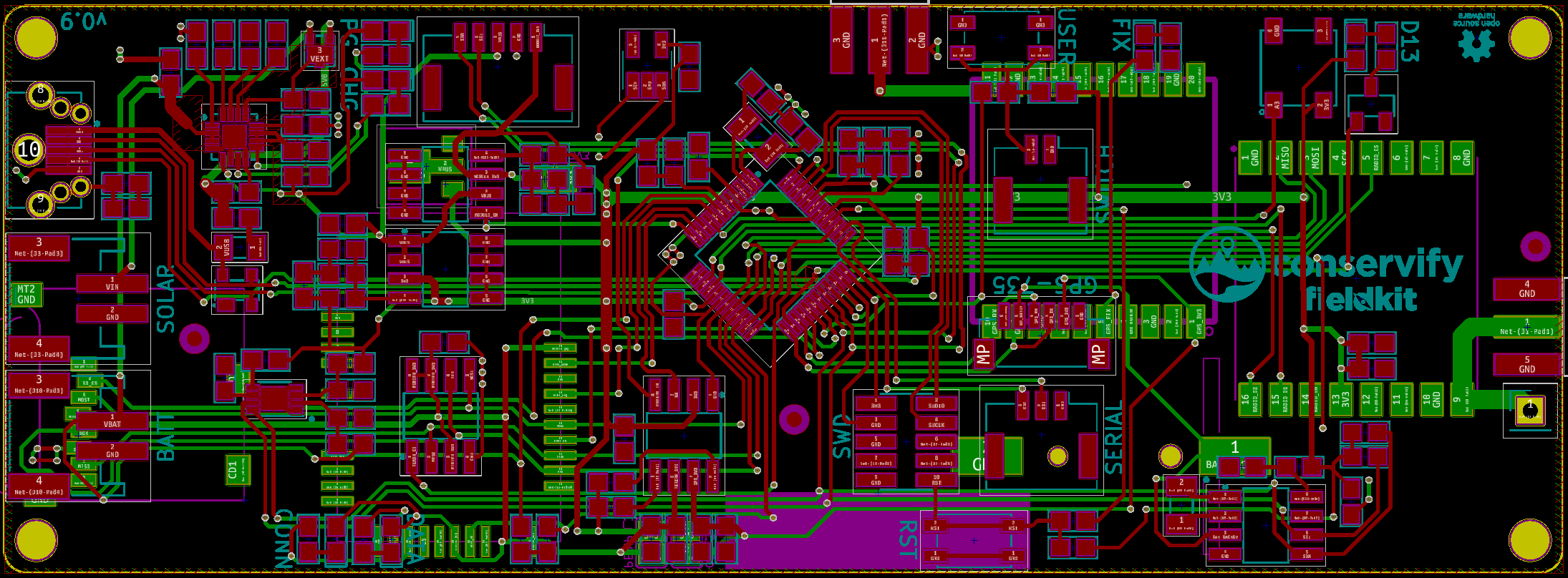
IRL, that ended up looking like this :
![]()
There were lots of decisions to be made at each of these boards, so I'm going to write them up individually in a series of posts starting tomorrow.
-
Remote Firmware Upgrades
08/23/2018 at 18:06 • 0 commentsWhen there's WiFi in the Amazon
Pretty much every sensor deployment we've done has been to remote areas with little or no connectivity. It can take days to reach some locations, either off roading through unforgiving terrain, boating in over crocodile infested waters, or hiking over rocks, ice, and snow. Sometimes we've been able to get status over satellite, but the bandwidth and power budget usually mean that the truly useful status and diagnostic information is left sitting idly on disk until the station can be visited again physically. It's stressful setting up a station and then leaving the poor thing behind, hoping that nothing was forgotten and that enough testing was done.
Over the last few months our efforts have largely revolved around some work we're doing with WCS and FIU in the Amazon jungle. Most of the stations there have been of the breed we're used to, left on their own to fend for themselves. Lately we got word that a future site would have WiFi, which for us is a pretty unique opportunity for a few reasons. First, we'll be able to get higher fidelity diagnostic information and data from these stations. In addition, given the right preparation, we'll be able to service the firmware on these stations remotely.
Being able to remotely upgrade firmware is a feature I've been wanting for a while. Given the state of the FieldKit project we've never really had a reason to expend the effort for the feature, though. This recent news was a great opportunity to justify that initial groundwork work.
Now that the feature is implemented and being tested, I wanted to write up a post going over what the feature took. So, get ready, this is a software heavy post.
Overview
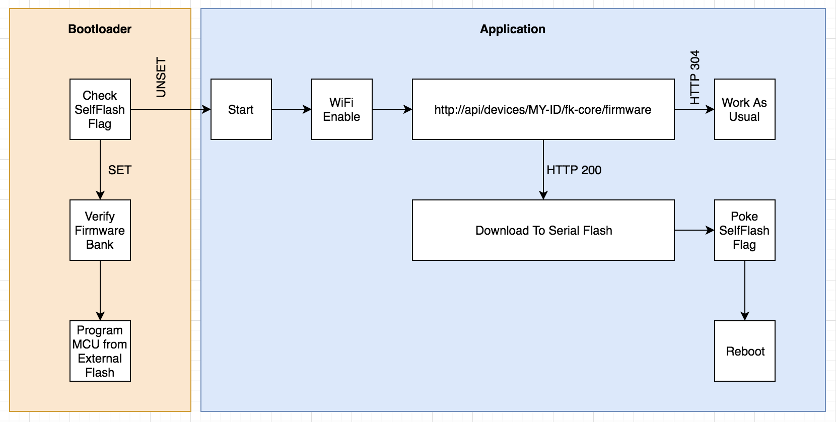
![]()
At a high level, the basic premise is that the station would periodically check with our servers to see if there is new firmware available. If there is, the firmware is downloaded and then stored in the Serial Flash chip. Once completed and verified, the MCU sets a flag in memory indicating the self-flash should be done and then restarts itself. At startup our custom bootloader checks for this flag, and if set will reprogram the MCU's flash memory from the binary in the external flash chip.
When remotely upgrading module firmware the process is very similar. The Core module (the one with the WiFi) will check to see if any of the attached module's firmware is outdated, downloading the binaries if necessary. Then that binary is transferred to the module over I2C, verified, and the module restarts itself in a similar fashion.
This is one area where us deciding to include serial flash memory as a standard "Module" feature was a good idea. This process would have been more awkward, otherwise.
It's important to us that all of the work we do fit comfortably within the OSS/OSH ecosystem that's evolved from Arduino and similar platforms. This work represents the largest deviation from that work, so far. Though it's possible to use our code/hardware with standard bootloaders and simply forgo that functionality in your own projects.
Digging into Bootloaders
Most "maker" focused development boards in the Arduino ecosystem come pre-installed with a bootloader of some kind. This is a small program, usually less than 8k or so, then runs before application code and provides friendlier ways of programming the MCU. For example:
![]()
- Presenting the MCU as a USB storage device so you can simply copy new firmware files over.
- Checking for "double taps" of a physical button that places the MCU in a "ready to program" state.
Now would be a good time to mention that all of our boards use the ATSAMD21G18 chip, the same one from the Arduino Zero boards and the Feather M0 line. So most of what's here applies to them and another Cortex M* chips.
Our task in the bootloader is to check a pre-determined memory location for a magic value to indicate that the application firmware has left behind new firmware that should be flashed. This is similar to how the "double tap" checks are sometimes done and so we opted to use that same memory location with a different magic value than what's used for the double tap.
This means that our custom bootloader had to learn a few new tricks. Specifically we needed:
- Access to one of the hardware UARTs for debugging purposes.
- Access to the SPI peripheral so we could talk to our external serial flash chip.
- File system code for accessing and reading the data in the serial flash chip (More on this later)
Note that most bootloaders are kept as small as possible so that more space is left over for application code. Once all the above functionality was implemented our bootloader had outgrown its original 8KB home, ballooning to around 22KB or so. On our chip we have 256KB of flash and our largest firmware weighs in around 150KB or so, leaving plenty of room for a larger bootloader. We settled on setting aside 32KB, for now.
File System
The proof of concept for this feature simply wrote the new firmware to a fixed location on the serial flash chip and the bootloader knew to start reading from there. From a wear leveling perspective this is probably fine given the infrequency of updates to firmware. Unfortunately, this basically dedicated 256KB of memory to these pending binaries. One thing we'd also started to investigate was storing a copy of the currently running firmware so that the device could decide to revert to a previous firmware if a problem was detected.
The serial flash memory was already being managed by our custom file system, Phylum and so we decided to add the ability to store variable sized files with that. Giving us a few other benefits that are best addressed in a post dedicated to the file system work. In the end, each board can store up to four binaries: Pending module and core updates and copies of firmware known to be good.
This was also nice because the code for manipulating these files works just how the code for manipulating files on our SD card does. While I'm mentioning the SD I should point out that because modules don't have SD cards it made more sense for us to build this functionality around the serial flash.
Server Side Firmware Juggling
One of the easier parts of this feature was the server side code to handle juggling our firmware and distributing them to the modules as they "call in" There were a few things I wanted:
![]()
- Specifying firmware at a per device level. Each device has a unique device-identifier and our tools allow users to specify which device should be running which firmware. This way we can test and run different binaries across a set of devices.
- Per module, per device firmware. One thing to keep in mind is that a particular station actually involves more than one board. For example a typical station would have one Core board and one Sensor board. When devices call in to check firmware they do so on behalf of each connected module and the Core itself.
- Bandwidth friendliness. Firmware should only be downloaded when the firmware changes. Just because we have WiFi in the Amazon doesn't mean we can abuse the bandwidth we've got.
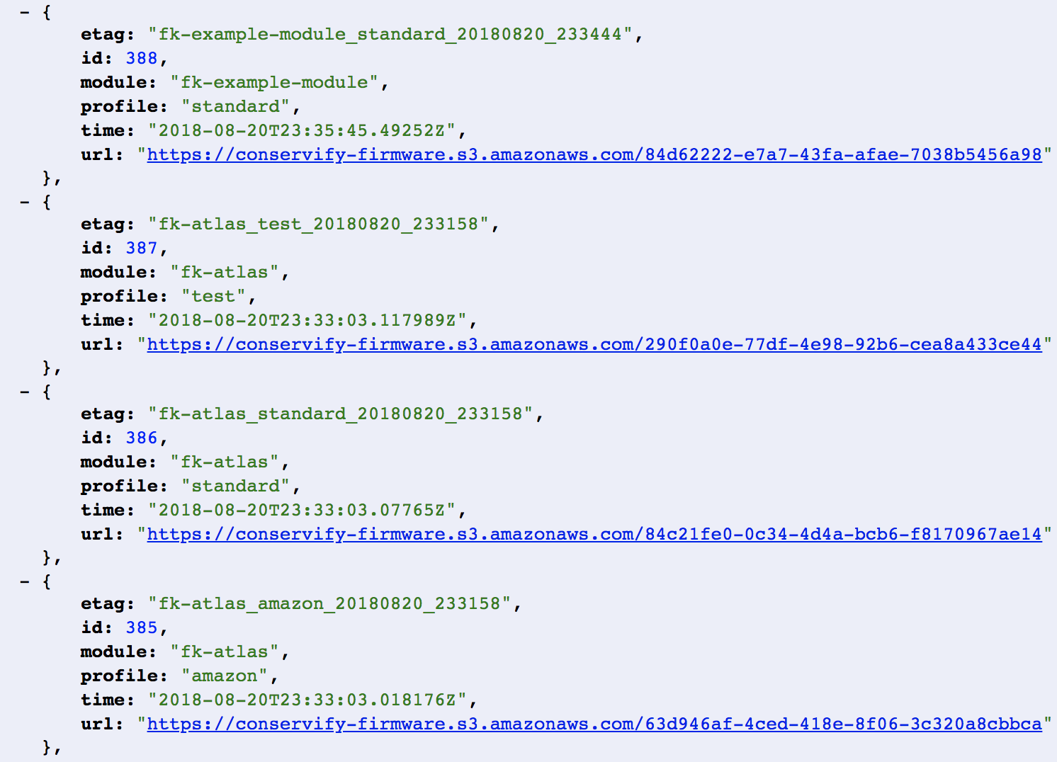
This means the Core firmware knows its own firmware version and the version of all attached modules. It then issues a query to our servers of the form:
https://api.fieldkit.org/devices/{device-id}/{module}/firmware
One of the headers we provide is the If-None-Match header that includes an ETag, giving the server the ability to respond with a small 304 Not Modified response in the case that the device's firmware is unchanged.
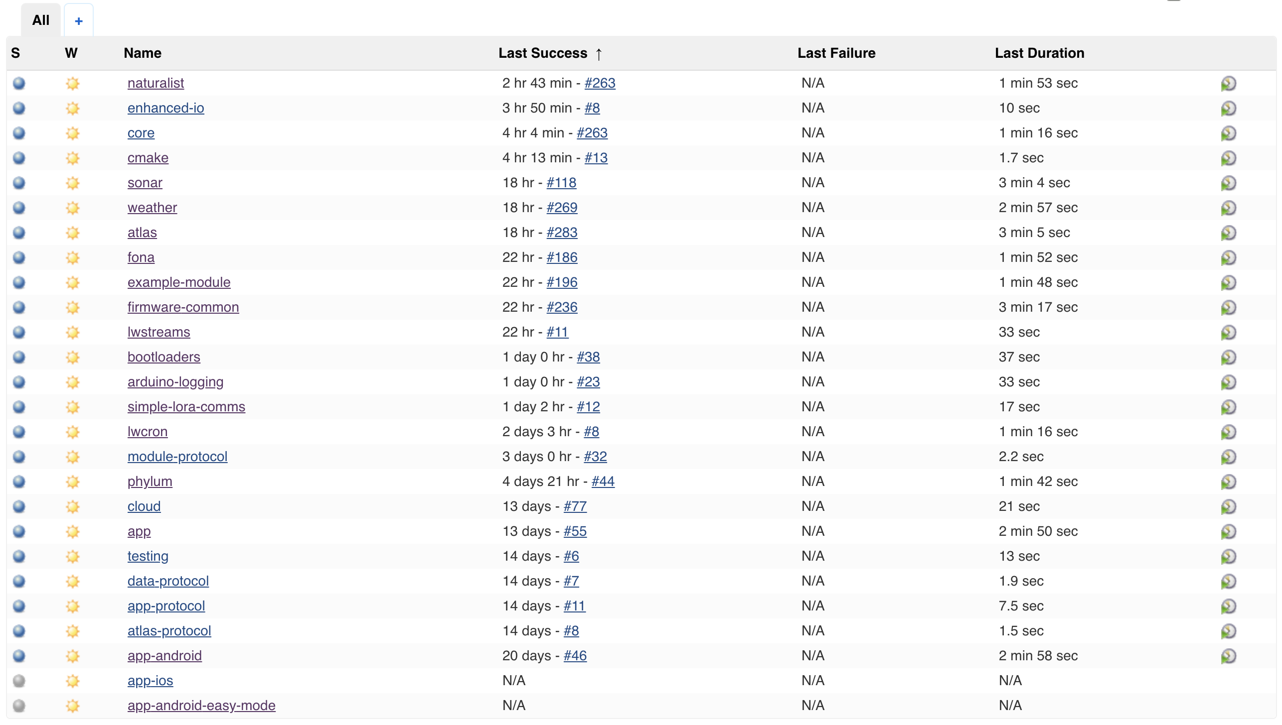
Build Server
![]()
I wanted to briefly mention that we rely heavily on our Jenkins server for managing our builds and some of our workflows. In fact, it's through this server that new firmware gets fed to the server so they can be distributed to devices. We're actually planning to write a dedicated post to the way we use Jenkins internally, but for now the basic idea is that after a successful build, the compiled and tested binaries are uploaded to S3 and the metadata for them is recorded in our database. We then have a tool that we can use to associate one of those firmwares with a device so that it'll be downloaded and flashed on the next checkin.
Future Work
I briefly mentioned giving the devices the ability to revert themselves when they discover a problem with new firmware. This is still in our backlog, until we can decide what exactly that criteria should be. For now, though, our goal is to test this remote update functionality as much as possible.
-
FieldKit's History and Future
08/08/2018 at 22:57 • 0 commentsBotswana's Okavango Delta is one of the most incredible places on this planet. Named a UNESCO World Heritage site for it's biological diversity, the Delta is a pristine habitat for all the charismatic megafauna that subsaharan Africa is known for: elephants, hippos, lions, giraffes, and more. It is one of the most incredible places that I have ever been and the need to monitor and protect it has never been more necessary. It was in this magical place where FieldKit was born, with support by the National Geographic Society.
FieldKit was inspired by a collaboration between National Geographic Explorers Shah Selbe, Steve Boyes, and Jer Thorp. Steve was conducting biodiversity surveys of the delta from canoes year-after-year in the same old ways that scientists have done for decades (if not longer). While working in the field in Botswana, Angola and Namibia, the team realized that there were few good open source hardware and software tools that met the specific needs of field research. Not only in sensor technology but also ways to organize and visualize the data. Responding to this need, Shah and Jer began to prototype software and hardware solutions and field-tested these approaches from 2014 to 2017.
We wanted to share the science and the story behind the expedition real-time, so anyone could join and provide insight or support. By turning Into The Okavango (ITO) into a live-data expedition, we have been able to bring thousands of people along with us on expeditions in the Okavango Delta (including an astronaut that was following along from the International Space Station). We collected, stored, and shared 40 million open data points and continuously measured ‘the heartbeat’ of this crucial ecosystem through large-scale open source sensor systems.
This experience we had with ITO was transformative, and it made us realize that we should bring these same capabilities to anyone anywhere in the world by giving them a publicly available, fully featured ITO of their own. The lessons learned and understanding that came from years of continuous field use allowed us to architect FieldKit in way that can be scaled and expanded across various users regardless of how much they know about engineering and computer science. Scientists have already been embracing social media and blogs to share their expeditions with the world visually, but there wasn't a good tool out there for them to do that same sharing scientifically. @Jacob Lewallen has been helping with the hardware and software development on a volunteer basis since the beginning, and stepped in as FieldKit's Principal Engineer at Conservify in 2017.
We already have additional working partnerships with scientists to use FieldKit in their efforts, which include:
- Handheld GPS-correlated environmental sensor laboratory developed with the National Geographic Society Labs that easily interfaces with iNaturalist and other online biodiversity databases.
- The largest partner for FieldKit is the Wildlife Conservation Society and the Moore Foundation for their Citizen Science for the Amazon project. This is deploying citizen science water monitoring and weather stations across seven countries in the Amazon Basin (covered in an earlier post).
- Gathering scientists data around UCLA Center for Tropical Research's Congo Basin Institute field stations at Bouamir, Cameroon.
- Deployment of a FieldKit camera module, as a request from the Wildlands Conservancy and U.S. Fish and Wildlife Service to monitor the first California Condor to return to the Wind Wolves Preserve. This will also stream the video live to a "condor cam" that will serve as a public outreach and conservation communication tool.
- Tracking changes to glaciers in Banff National Park, in partnership with Parks Canada, University of Alberta, and Office for Creative Research.
- Measuring water quality along a mythical boiling river in the Peruvian Amazon (partnering with the Boiling River Project, Southern Methodist University, and the villages in the community).
- … and many more currently in development.
-
Learning by Doing
08/01/2018 at 23:33 • 0 commentsIn our previous post, Shah outlined our most recent project with the Tropical Rivers Lab at Florida International University and gave a high level overview of the work we've started with them. I wanted to take some time to talk about how valuable the real world work is in providing feedback on FieldKit ecosystem.
It's inevitable in field work that you'll find yourself working with conditions or constraints that you didn't anticipate, even more so when you're the one who has designed the hardware you're using. Ever since my first field experience I've tried my best to keep meticulous notes on the issues I encounter, their solutions, and ways they could be avoided and mitigated in the future. These notes are incredibly valuable compared to in-lab testing of hardware and physical enclosures by virtue of many important facts:
- They are often taken outside of the lab, without access to the tools and parts that are available during development.
- They include insight from volunteers or partners that aren't present during the day to day in lab testing.
- Not every field installation is identical and always brings some unique challenge to bear on the hardware.
- There tends to be a difference in scale that has an impact on my mindset. For example, assembling 10 stations is very different than assembling 1 for an in-lab test, making bottlenecks and physical improvements more obvious.
I'm going to quickly go over some of the changes we've made recently, directly due to the efforts of preparing these stations for the field.
Physical/Hardware Changes
![]()
Size
Board sizes evolved haphazardly until recently. I've begun rounding them to easy to remember dimensions.
Connectors
Oh connectors. Connectors have been one of the largest frustrations I've had. We've recently begun incorporating Molex connectors on our boards to link modules to the Core board. The connector is a 5 position one, carrying I2C, power, and Vbus (unused for now) This went so well that one change I wanted to make was use them for even more things, not just the Core/Module connection. We decided to increase our use of these connectors in these ways:
- These stations were the first to incorporate an external user switch, which was exposed via an awkward through-hole header. This became a 2 position Molex.
- Weather stations have two PCBs, one main weather module and a board we call the sensor board that's housed in a Stevenson screen. One end was already Molex and for some reason the other end was not. These things happen. The learning experience here though, was that the Molex on the sensor board should be on the bottom of the PCB for easier mounting.
- Our water quality module had a 4-position "sensor" connection already. We carried this pattern across all our module boards because it's become common to attach secondary sensors to various modules.
- We added second Core connectors to all modules so they could be daisy chained in the future.
Vertical Entry vs Side Entry
![]()
So far used we've been using side-entry USB and JST connectors exclusively. Somewhere around the third board I realized that vertical entry USB would be way more useful in situations where the enclosure is an off the shelf box. Side entry, especially on the ends of boards, requires internal space to be be able to use the connector. Otherwise, you've got to lift the board from inside the enclosure to insert a USB cable when flashing or charging, etc.. The same goes for the JST connectors we used for batteries, though to a lesser extent because they tend to be more maneuverable than USB cables. Right now we're testing hybrid USB and JST footprints that allow either part to be soldered on. We'll be reporting back on how successful this is, especially with regard to the frankenprint we're using for the USB.
We'll also be moving to vertical buttons, as well.
Connector Locations
Our solar panel JST was on the bottom of our Core board, simply because room for connectors tends to be pretty limited. This was annoying, and so future boards will have the connector on the top.
We are also striving to keep connectors and LEDs grouped to facilitate stacked mounting situations. For example, we mounted the Core board over the Atlas Water Quality module, leaving the latter's side exposed where nearly all of the connectors were. This was very nice, and could have been nicer if all the connectors were along that edge.
![]()
Mounting Holes
Our mounting holes are pretty small, a symptom of them appearing so large when laying out boards in Kicad. This made the hardware frustrating to use and in at least one case there wasn't enough clearance for the nut because of PCB parts. So all boards got 2.54mm diameter mounting holes with special attention paid to clearances. Another change we're hoping to make is standardizing the pattern across modules and Core to make mounting easier.
Solar Panel Hardware
We use Voltaic panels pretty much exclusively at this stage. We learned far too late that Voltaic has a number of accessories that can make their panels more pleasurable to work with:
- Extension cables with various connectors. Notably JST and exposed leads. This is nice because we often attach panels in the field during installation and being able to dangle the extension outside of the enclosure makes that process easier.
- Stainless steel post nuts. Anybody that's used these panels has probably been confused by the plastic nuts they ship with.
- Mounting brackets and corner mounts. They even provide designs so you can fabricate your own. Mounting these panels to enclosures is a task that's only just now finding some solid ground, until recently it's been one of the uglier tasks.
Status LEDs
Our boards have typically included three status LEDs arrayed the same way on all boards. This didn't pan out exactly the way I had intended and so we've decided to try out the Neopixel status LED like you're seeing on newer boards from Adafruit and the Particle boards.
Software Changes
By the assembly stage the software is mostly pinned down, but a few things came up in my notes.
One of the sites we'll be deploying to in the future will have Wifi, which is a first for us and means there's some things I'd like to have ready to go for that installation. Specifically, the ability to remotely upgrade firmware. This has been one of my focuses over the last week. This has meant a custom bootloader that can read firmware from our serial flash chip into the flash of our MCU. With that in place we've got other sever-side infrastructure for deploying firmware binaries from our Jenkins/CI server to the cloud where they're cataloged. It's now possible to set the firmware on a per-device basis, and devices will download that firmware on a pre-defined schedule. Next steps here are being able to flash modules, which is slightly more involved because the firmware has to travel from the Core module Serial Flash to the Module's Serial Flash.
I've been unhappy with our internal scheduler and so moving to something more flexible has been important. We've recently introduced a new "Cron-Like" scheduler for tasks.
Next Steps
Right now my focus is on the remote firmware flashing and testing the hardware changes outlined above. We're also doing some research into replacing our voltage regulation section due to supply chain issues and we'll have a future post on that frustrating experience. Until next time!