 Sproket
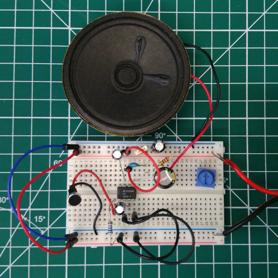
An electret microphone amplifier circuit using an LM386 has been successfully tested. With an additional capacitor between pins 1 & 8 for 200x gain, the amplified signal is a bit overkill. A potentiometer wired as a variable resistor will need to be included for setting the correct gain. This gain value could be fixed, but when using a microphone inconsistent input volume is to be expected.
Microphone amplifier schematic

Microphone amplifier on breadboard. Using a speaker for output testing there is lots of feedback, especially when C4 200x gain capacitor is fitted.
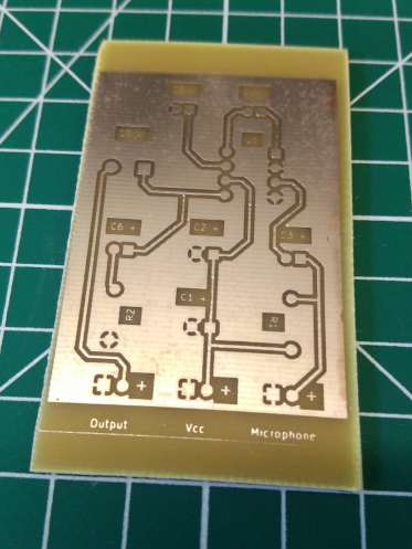
Printed Circuit Boards. This etched board shows version two of the layout with a corrected IC footprint and addition of component idents on the top copper layer. Components are on the bottom layer due to it being a single-sided PCB. Kicad can get confusing with idents being pushed to a different layer than the footprint, but it is workable.
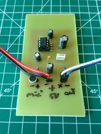
First revision of PCB. Assembled and working.
Discussions
Become a Hackaday.io Member
Create an account to leave a comment. Already have an account? Log In.