 Insight Machines Lab
Trying out the speed and cadence gauges (video shows version 1.0, with slightly different dials and without LED illumination):
The main source of inspiration for this project was a desk clock built with analogue voltage meters and ATmega328 (article in Polish). For our project, we decided to use the smaller an less power hungry ATtiny85 running at 1MHz. The power comes from a CR2032 coin battery which should last for around eight months. We decided to use magnets and reed switches from a modern Sigma bicycle computer - mainly due to their low cost and reliable mounting. There's also a switching voltage regulator to make sure that the signal that goes to the voltage meter is always in the same voltage range (0-3.3V) despite the falling voltage of the battery. The regulator is a contentious issue as it uses a lot of power but we have not found any sound alternative. We're using a regulator that has a standby mode so when the gauge shows zero, the regulator is shut down.
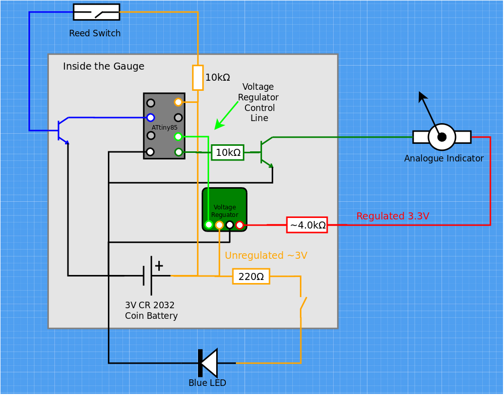
The diagram below shows how all the components are connected together:
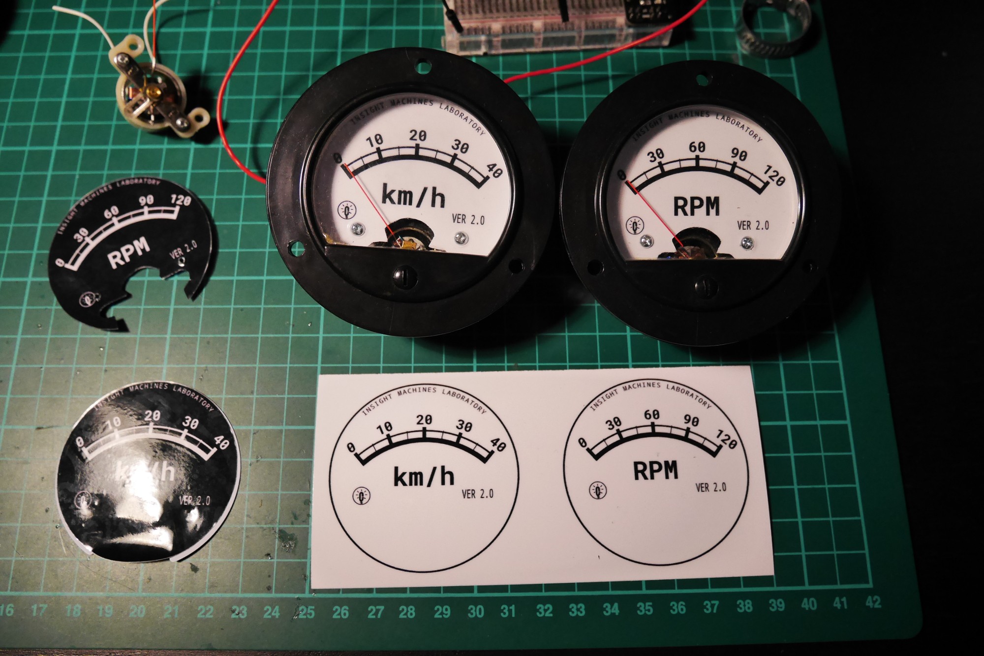
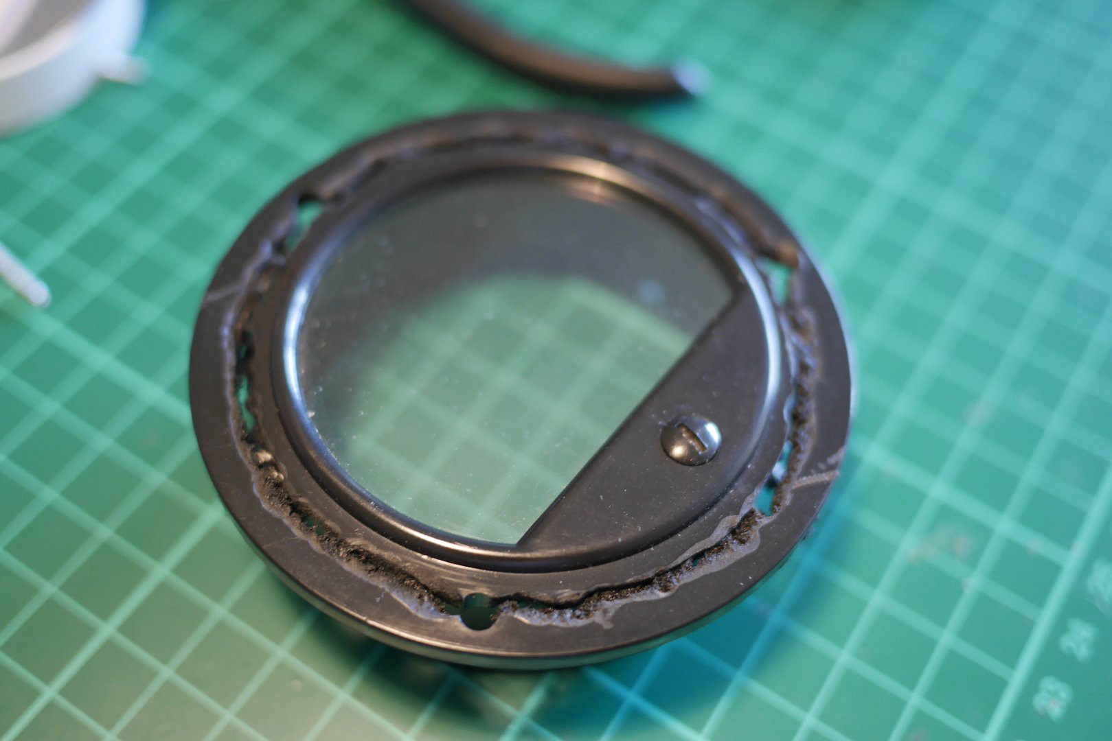
The components fit nicely into the voltage meter's enclosure:
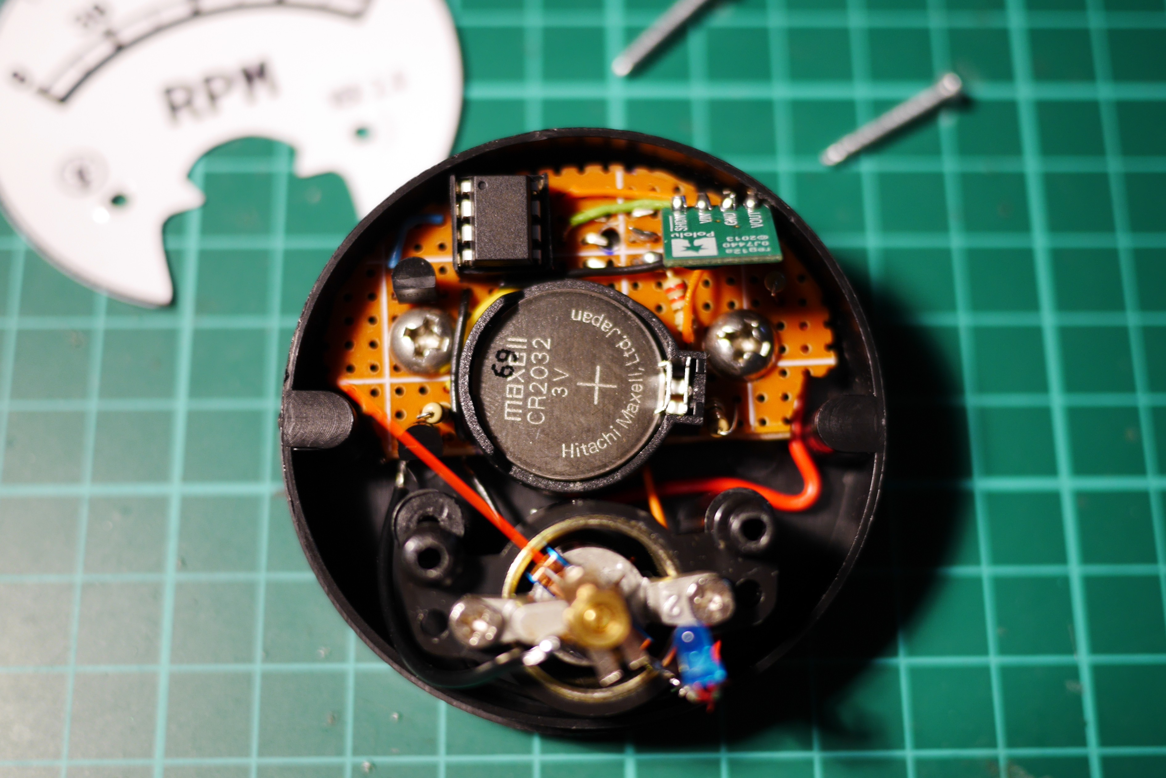
The screws, visible on both sides of the coin battery, hold the board in place and at the same time act as terminals for the reed switch. Thus, one of them is connected to the regulated power source while the other is connected to the gate of a NPN transistor and pulls down an ATtiny85's PB3 pin whenever the reed switch closes. This in turn causes an interrupt in the software that records the time of the signal. The speed/cadence value is calculated from the time difference between signals.
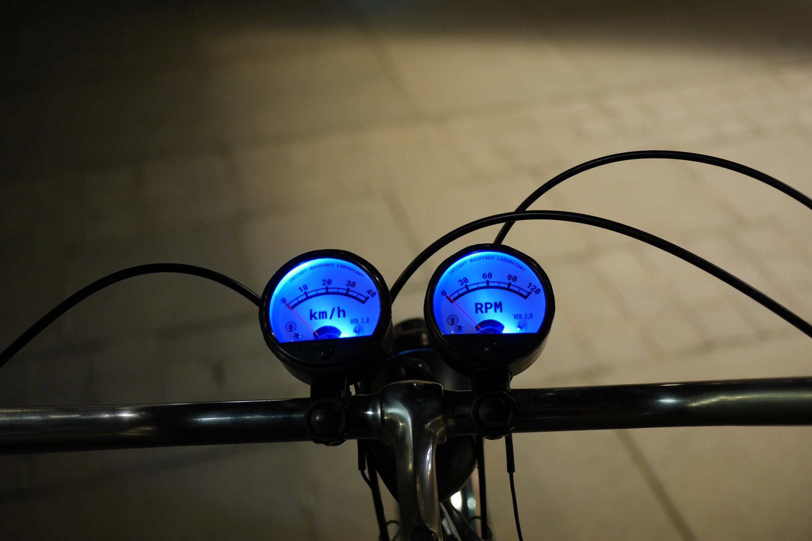
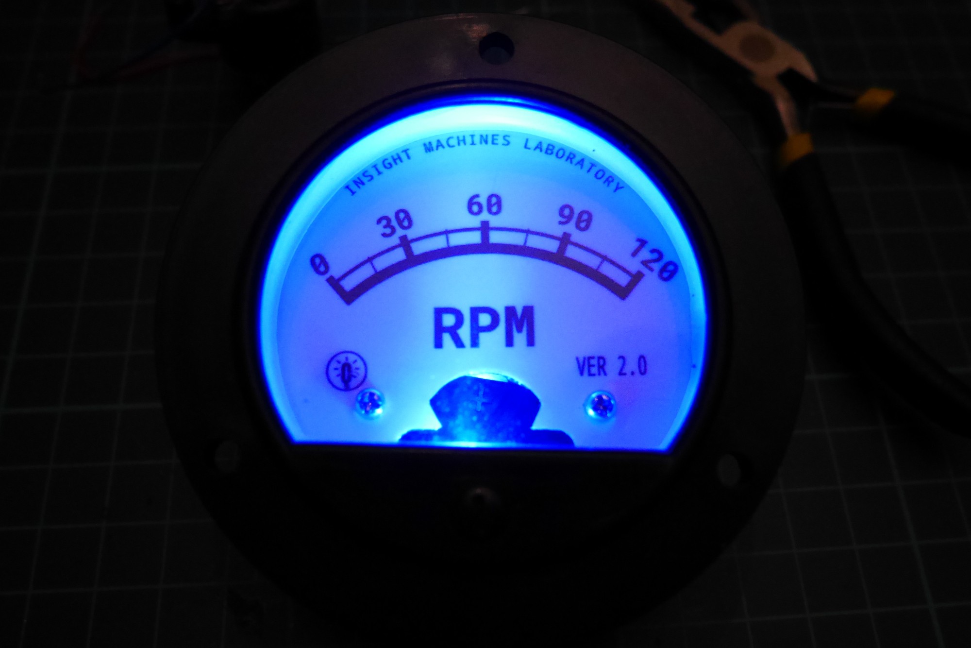
The gauge has a single blue LED that illuminates the dial. It is very useful after dark and adds a nice, cool look to the gauges:
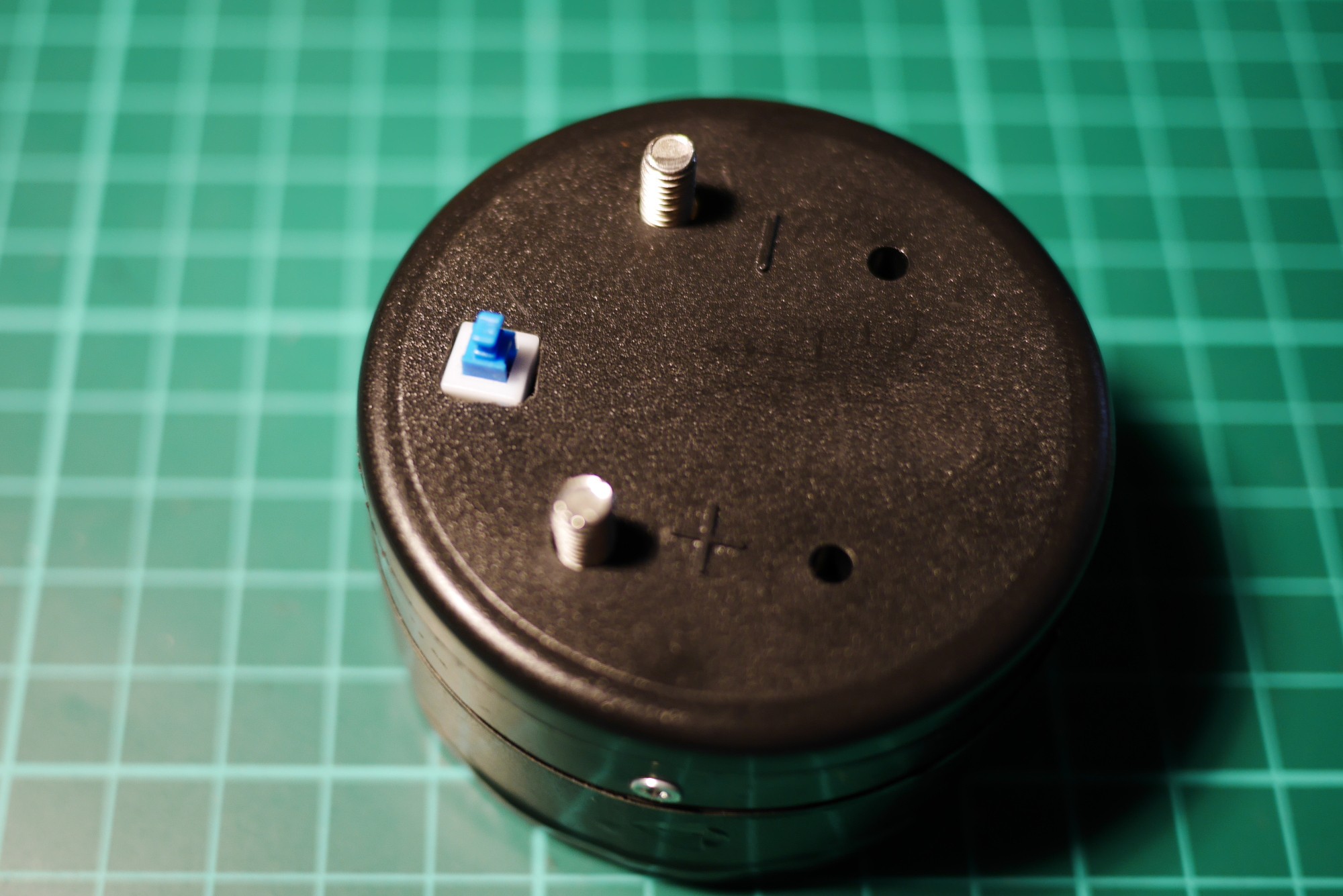
The LED can be switched on and off using a simple spring loaded button at the bottom of the gauge:
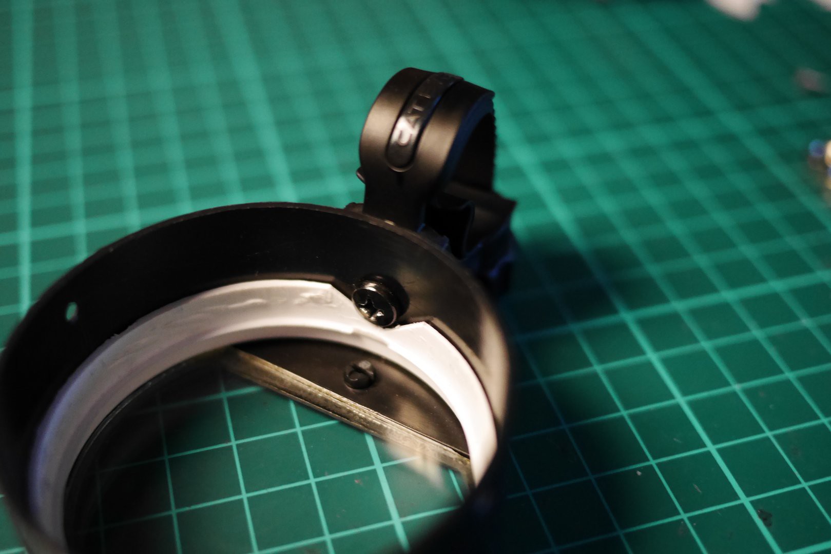
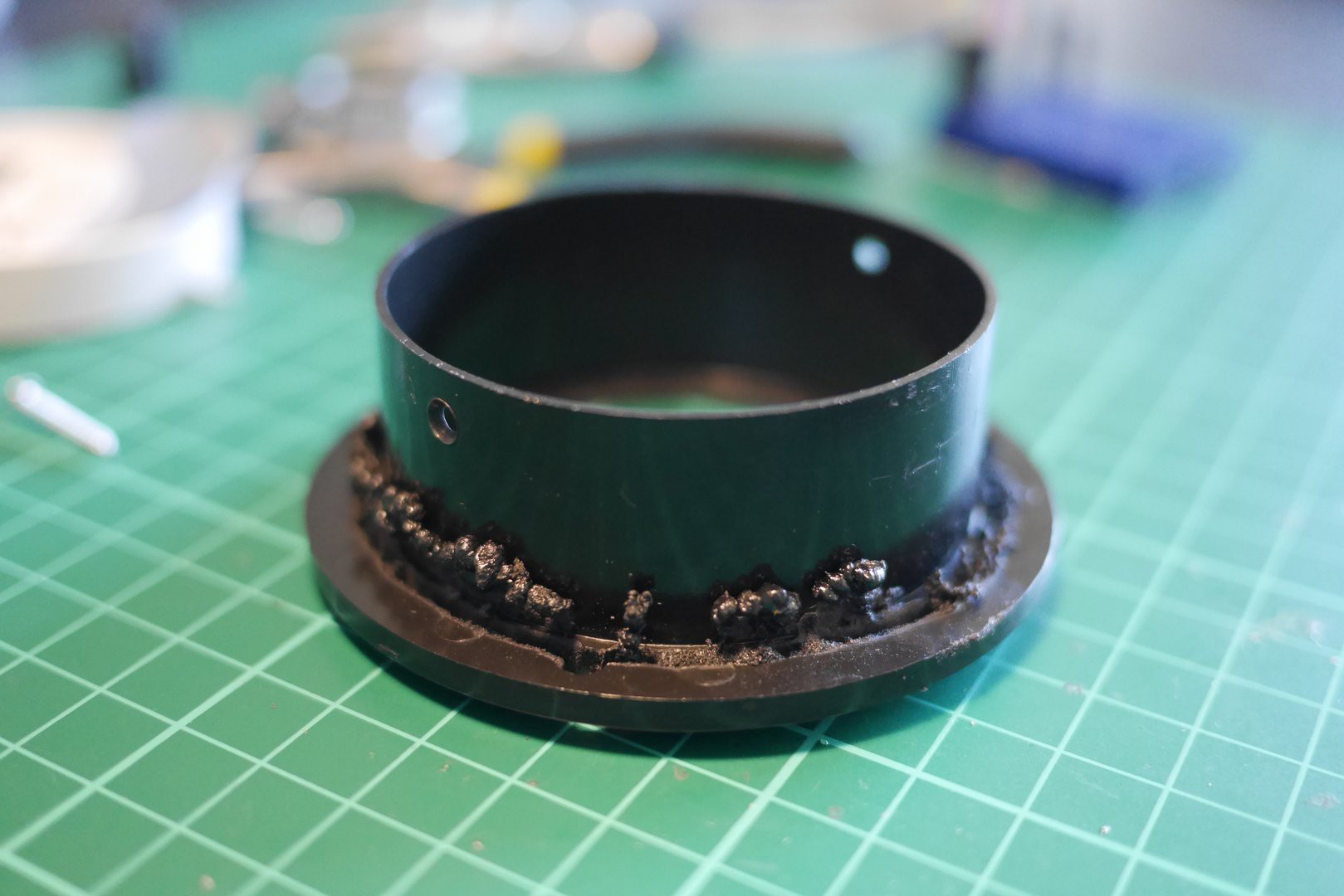
The gauges are mounted on the handlebar using a plastic band with a worm-like drive. Tha band was adapted from a Cateye headlamp:
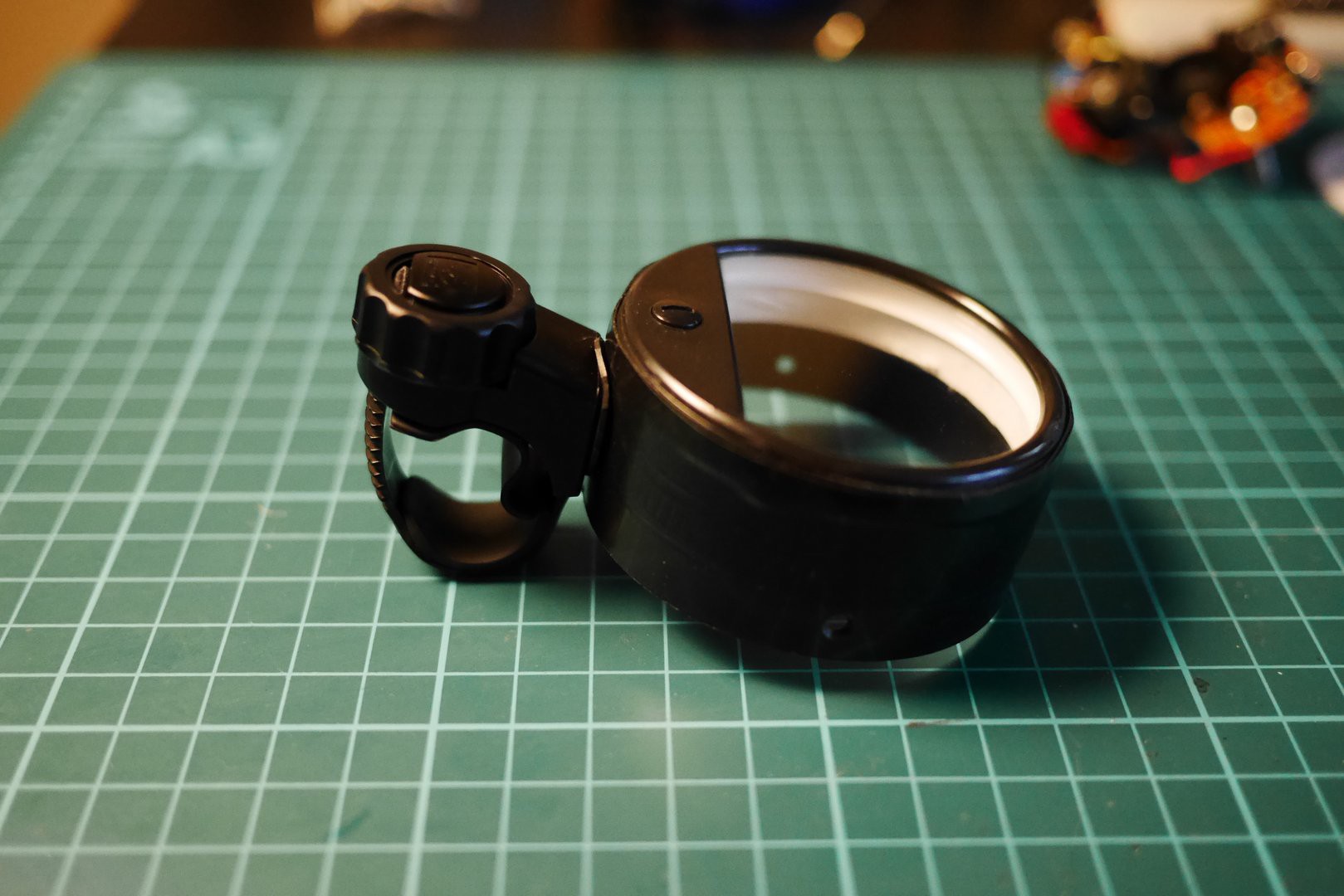
It is attached to the gauge's "can" with a single screw:
At this point, we consider the project complete. The gauges obviously need some tweaking but all in all, the devices work as expected and are sufficiently reliable.
 ... But it has to do.
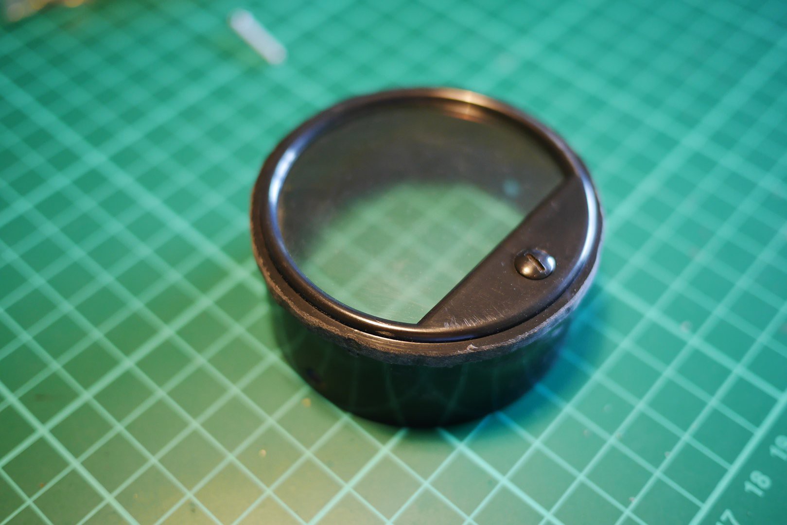


Cool Project !