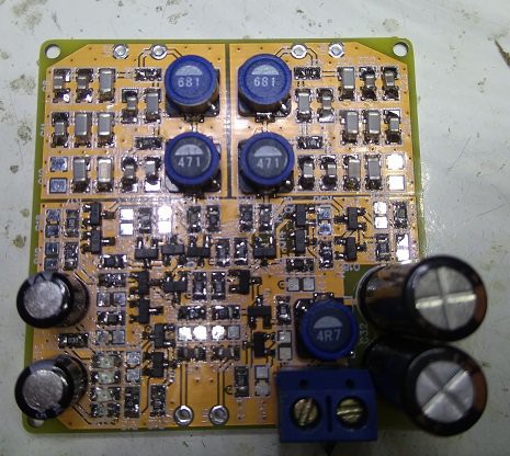
Since the new DAC board reduced the number of DAC chips to two, a new filter-I/V board was called for which was able to run on half the signal current. Here it is - there are a few significant changes :
- Filter inductors are increased in value as now the filter has a higher characteristic impedance (about 50ohms)
- Capacitors which were X7R have been replaced by NP0 - increasing the filter impedance has made this practical. The main advantage of using NP0s is their closer tolerance and much better stability, meaning the filter build no longer needs a long time fiddling to get the right cap values.
- This board runs on 9V which means it can now deliver the industry standard 2VRMS DAC output signal, if desired. Although the supply voltage has gone up 50%, the current draw has gone down so this board consumes less power.
- The I/V stage is a bit more complex but the new circuit has better compatibility with alternative DAC chips. I plan to try this with the TDA1387 but powered from 3V (rather than 6V as at present) which wasn't practical with the first generation board.
- It sounds a little bit better too - there's slightly more detachment of the images from the speakers.
- The BOM cost has gone up (NP0s being dearer than X7Rs) but OTOH the build time has gone down markedly.
 Richard Dudley
Discussions
Become a Hackaday.io Member
Create an account to leave a comment. Already have an account? Log In.