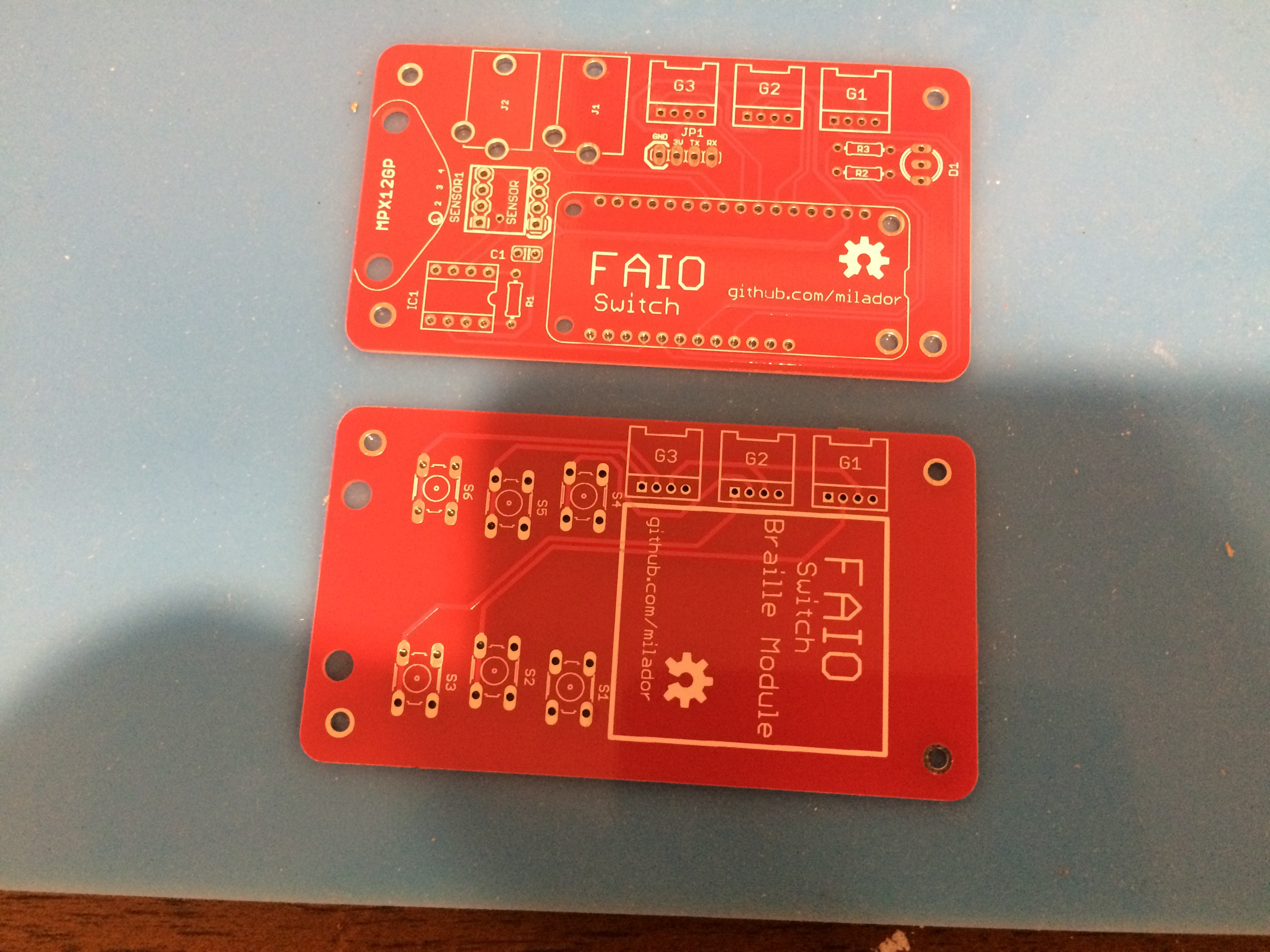
I received the PCBs in mail last week and they look great as you can see below:
The first board is the main board with 2 3.5mm jack connectors,3 Grove connectors,and pressure sensor for Sip-and-Puff switch.
The second board is the braille module which will be connected to main board through 3 Grove connectors.
 Milad
Milad
Discussions
Become a Hackaday.io Member
Create an account to leave a comment. Already have an account? Log In.