Headset Development
The current headset is defined by the R200, which is an ungainly rectangular block that doesn't fit anywhere on your face. Comparing it to Geordi's visor is complimentary, but probably not a good sign for users who want to avoid the fashion statement.
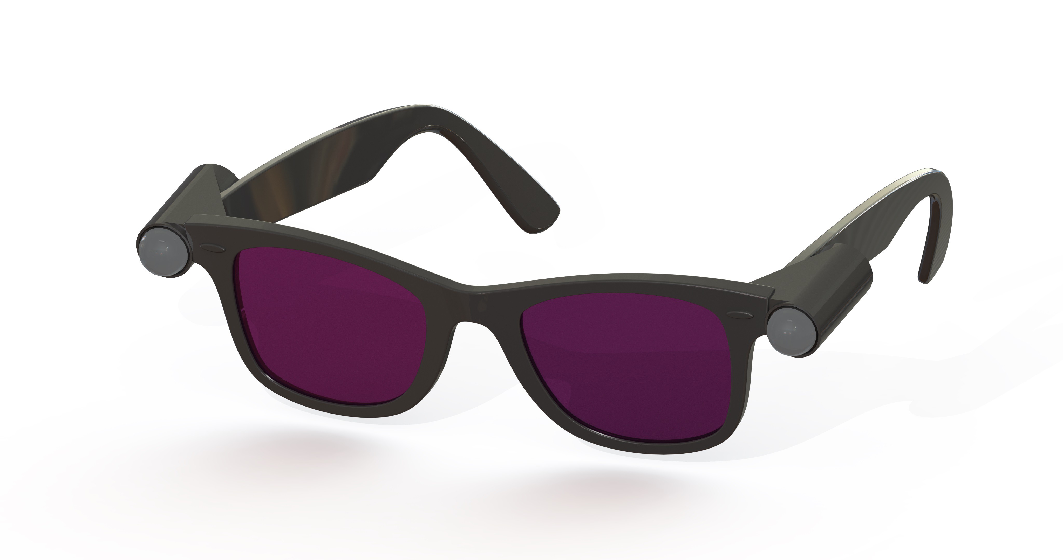
The future SVO headset will take into account feedback we've gotten about our current design to keep the eyes free of obstacles so that partially sighted individuals can take advantage of all of their senses. Some of our concept art explores integrating cameras into more popular eyeware to take advantage of the aesthetic benefits.
 Some considerations for a headset like this:
- Flexure of the frame will cause misalignment of the cameras which may make SVO impossible to accomplish.
- Headsets should come in both clear and shaded lens options.
- Three cameras may be better than two for achieving the desired 180° FoV.
- Each camera will require a controller which will take up much more space. This could be located behind the head, or merged with the earpiece.
- Communications lines may be routed and merged behind the head.
- It is probably not desirable to merge the earpieces directly with the headset. It would be inconvenient to need to remove/replace them each time the glasses were removed for cleaning or adjustment.
- Communications could be routed through the earpieces. USB connection to the earpiece could be made via magnetic jack for ease of use.
Controller Development
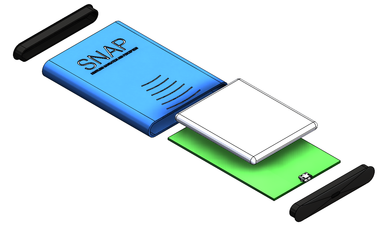
To reduce costs, the controller housing will be as simple as possible. This concept uses a preexisting aluminum extrusion profile which has been cut to length and anodized, forming the entirety of the chassis in one solid body. Milled features are shown in this image, although the intricacy of the text would likely prove to be cost prohibitive. Silk screen or labeling are more realistic options.

Some considerations for the chassis:
- Dimensions of chassis shown are 3x4x0.5 in
- Battery life can be extended by omitting a fan, but the board is likely to overheat unless extremely low power components can be utilized. Cell phone components may be sufficient.
- Plastic end caps will support the PCB at each end, pressing high powered components against one face of the chassis, while the battery pack takes up the majority of the underside of the board.
- Clear anodize would make for a more effective thermal solution.
Exploded Assembly
Removing the endcaps we are able to slide the PCB out either end. These end caps will either glue in place, or snap in with an interstitial gasket. The former option would make for a better seal, possibly up IP67 depending on the USB C connectors available. But can we resist making it SNAP together?
The FPGA/SoC would be placed on the far side of the board. Considering the size of the battery, this would nearly need to be a one sided board. It is likely that the battery will need to be larger still, and that the chassis will need to grow. The overall footprint is on par with an average cell phone, but because we will be powering two cameras and headphones and be running image manipulation continuously, it will consume quite a bit more power on average.
Better hardware estimates will be available after we have created a SVO prototype and have a firm grasp of the processing power required.

 Dan Schneider
Discussions
Become a Hackaday.io Member
Create an account to leave a comment. Already have an account? Log In.