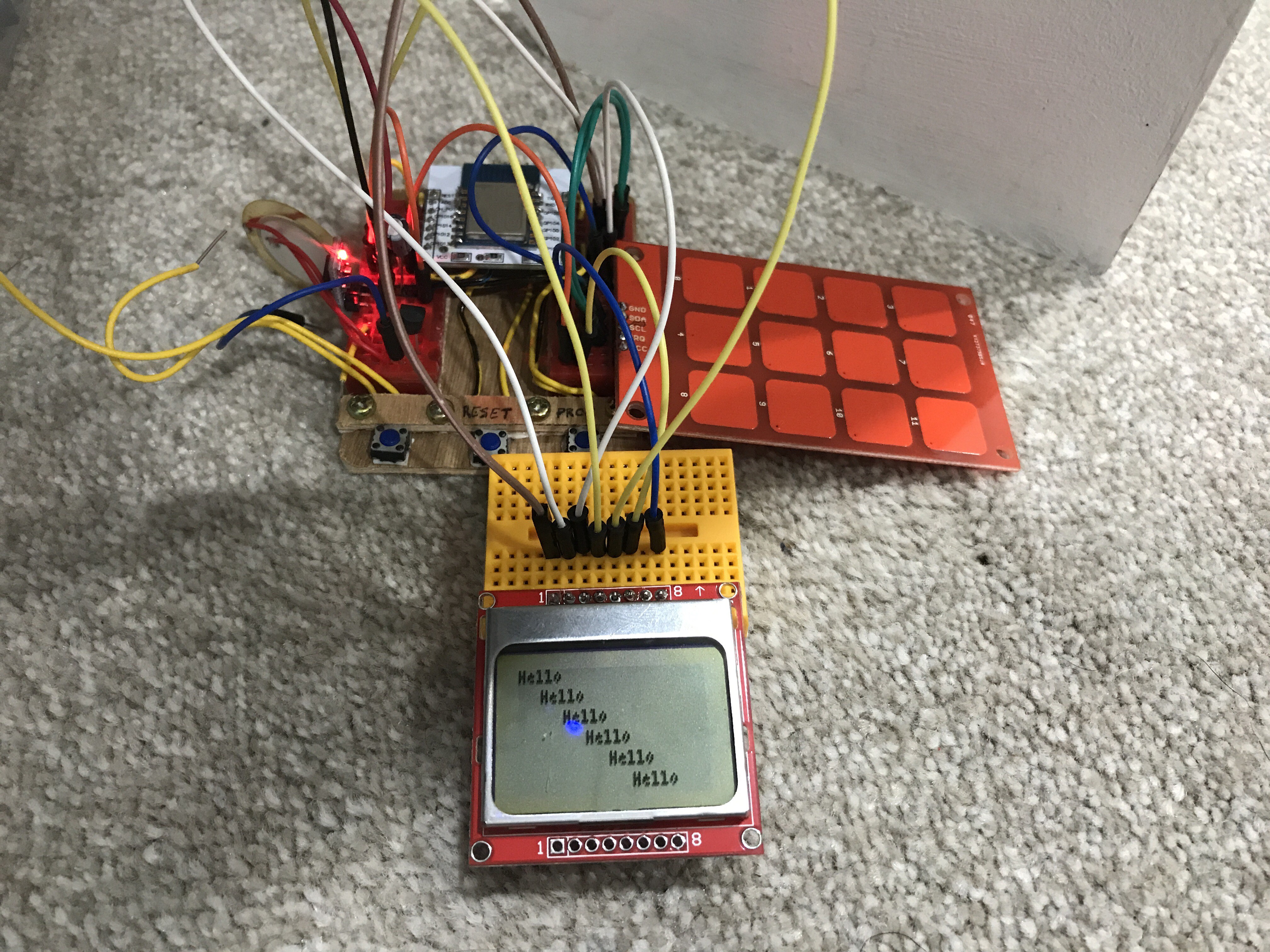
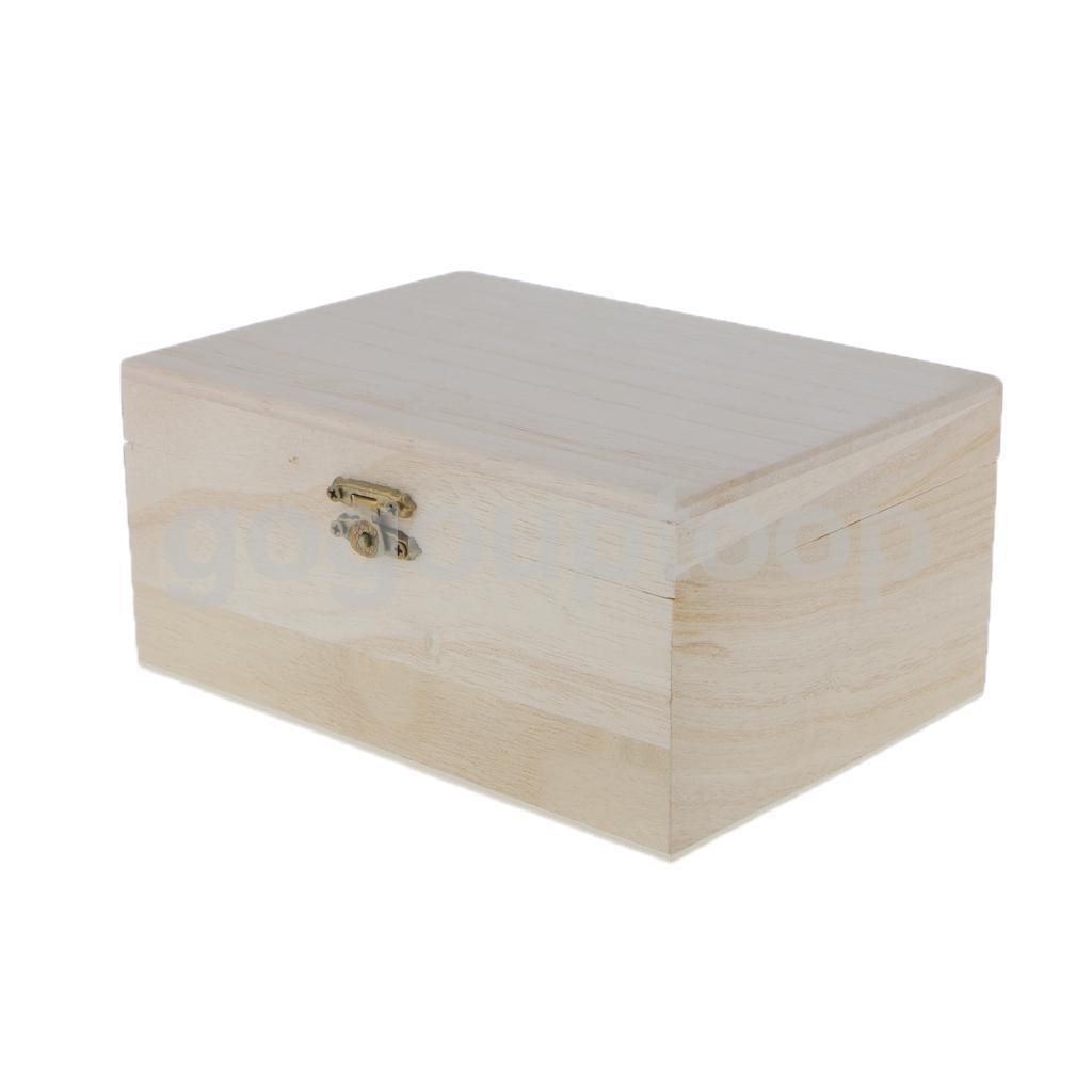
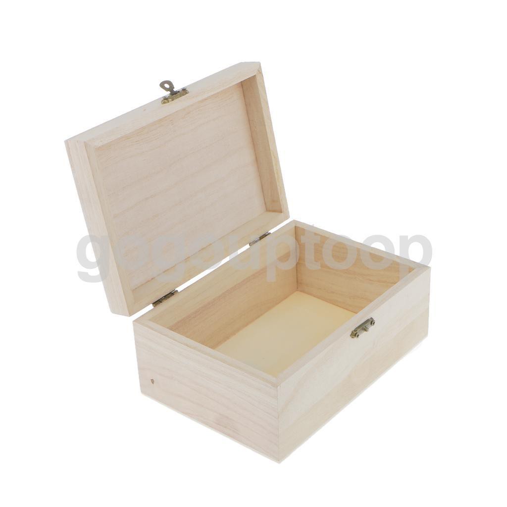
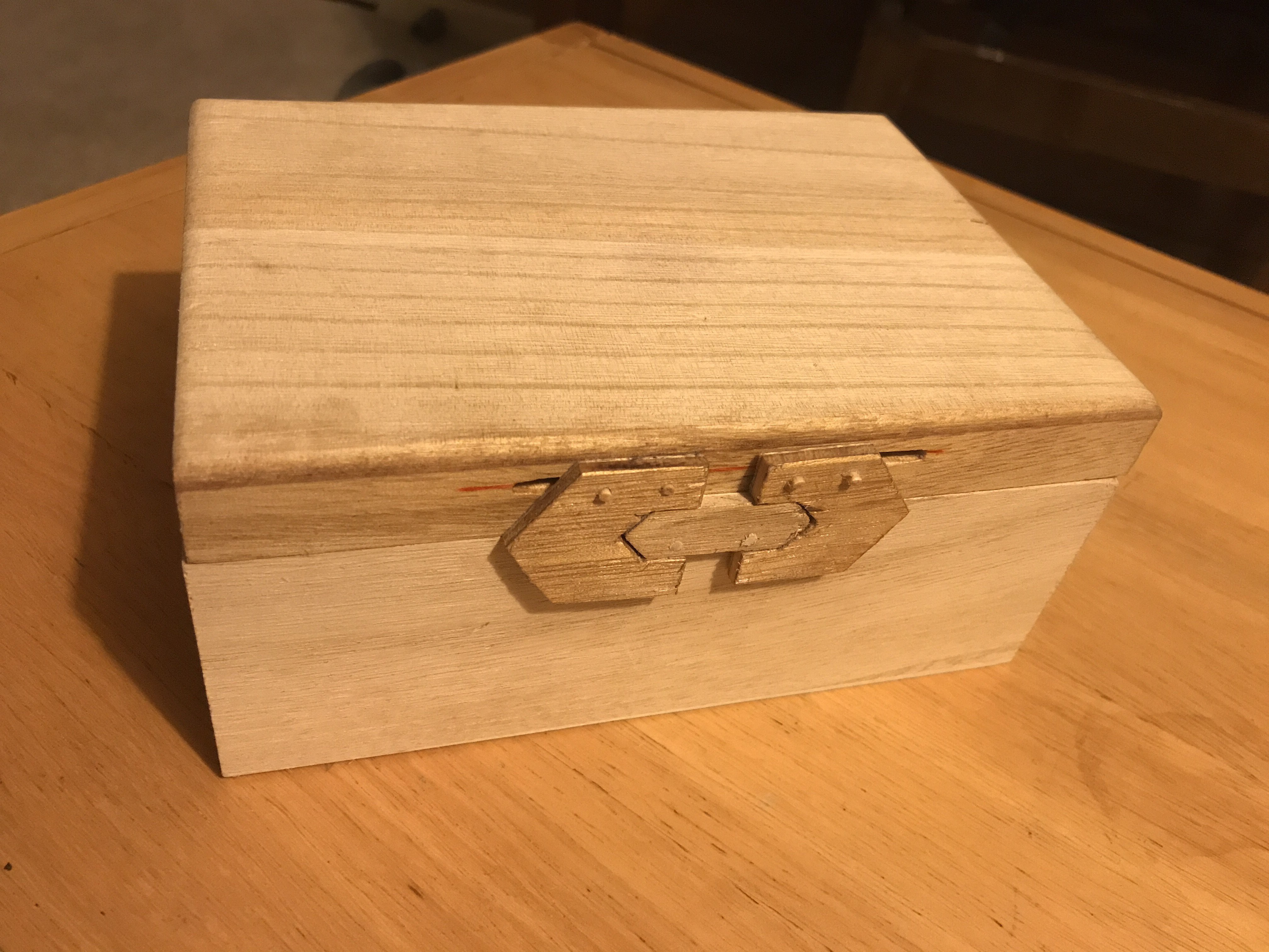
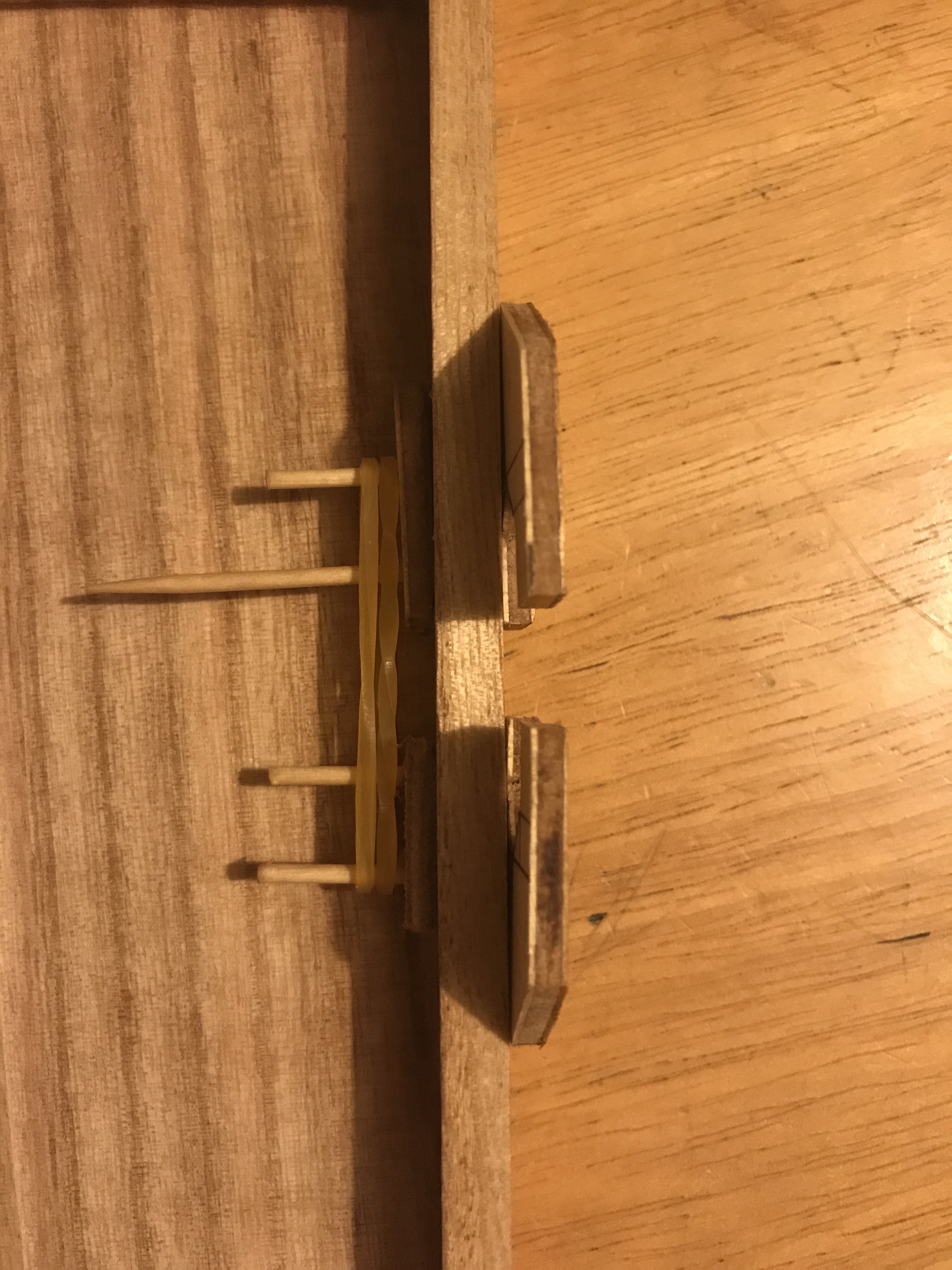
Intended to get a school-averse 7 year old to practice maths
To make the experience fit your profile, pick a username and tell us what interests you.
We found and based on your interests.
The software didn't start well.
After flashing the Espruino firmware to the first ESP-12 module, I found it rebooted every 10s. I put this down to an errant watchdog timer persisting from a previous use of the module.
I tried with a new module, and found it a bit more stable, but Espruino wouldn't run more than a few instructions without the module crashing.
Having had no problems with ESP8266 projects before, I decided the Espruino developers must be putting out really bad stuff.
After a lot of googling, I decided perhaps the PSU was at fault, so ordered a better PSU (800mA) to replace the 250mA one I was using (which had done fine for all previous ESP8266 projects). This solved it... :)
The Espruino ESP8266 support is ok, but the docs are a bit lacking; in particular, working out how to use SPI and I2C gave me some grief.
SPI
Here's the code I eventually got working:
SPI1.setup({ sck:D14, mosi:D13 });
var g = require("PCD8544").connect(SPI1, D15 /*DC*/, D0 /*CE*/, D2 /*RST*/, function() {
g.clear();
g.drawString("Hello",0,0);
g.drawLine(0,10,84,10);
g.flip();
});
Remember, SPI pin labelling isn't TX<->RX like UART; it's MISO<->MISO, MOSI<->MOSI.
I2C
i2c = new I2C();
i2c.setup({scl:4,sda:5});
var pressed = false;
function checkKeys()
{
var k = mpr.touched();
if (k == 0)
{
pressed = false;
return;
}
if (pressed)
return;
pressed = true;
switch(k)
{
case 256: key(1); break;
case 16: key(2); break;
case 1: key(3); break;
case 512: key(4); break;
case 32: key(5); break;
case 2: key(6); break;
case 1024: key(7); break;
case 64: key(8); break;
case 4: key(9); break;
case 128: key(0); break;
case 2048: del(); break;
case 8: enter(); break;
}
}
var user_str = '';
function key(num) {
user_str += num.toString();
console.log(user_str);
}
function del()
{
user_str = user_str.substr(0, user_str.length -1 );
console.log(user_str);
}
function enter()
{
console.log("ENTER: " + user_str);
user_str = '';
}
function ready() {
//mpr.setThresholds(touch, release); // 15, 8 For typical touch application, the value can be in range 0x05~0x30 for example
setInterval(function() {
checkKeys();
}, 50);
}
var mpr = require("MPR121").connect(i2c, ready);
Piccies:
Here's the box I'm using as a starting point:
Basic design considerations:
So it looks like a pre-made box is preferable; my woodwork skills suck, and it'll provide a solid, robust starting point.
ESP8266 provides an OTA-updatable controller.
Screen requirements aren't huge; pose a simple question, and ideally some space for a progress display. I've got a Nokia 5110 screen module lying around, so that'll do for a screen.
Keypad – I had an MPR121 module to hand. Initially I imagined using this to create a keypad with nails or similar stuck through the wooden box & sanded flat, but from a little reading it became apparent quickly that designing a capacitive keypad is a small artform in itself, so for now I've gone for a pre-made keypad.
Espruino may not be the optimal way to program microcontrollers, but it does provide an easy way to update portions of the code (the questions), and js is very user-friendly. It also provides robust maths and string-handling features.
The box needs a servo-activated lock to allow it to open at the correct point.
The simplest solution would have been a servo rotating a catch into a hole inside the box, similar to how has been implemented for many reverse-geocache projects.
But I decided I wanted to replace the catch that came with the box with an external locking mechanism; it feels much cooler, and provides an external visual feedback that the box has been unlocked.
This design was inspired I'm sure by something I've seen in a computer game somewhere.
The lock parts are cut from 6mm ply. I would have been much easier with a laser cutter, but I've not got one, so it was done by hand. The pegs are cocktail sticks (2mm dowel). Note that they've not been sanded down yet.
Here's the box closed. The central 'lozenge' shape is attached to the body of the box, and the two 'c' shapes are attached to the lid.
The 'c' shapes run in two slots in the lid, so they can slide outwards to release the catch. I'll use a servo to control this.
Detail of the lock; the rubber bands are a temporary option to use it as a manual lock. I've not trimmed the dowels as I'm not sure how long I'll need them for the servo.
Create an account to leave a comment. Already have an account? Log In.
Become a member to follow this project and never miss any updates