 jean.perardel
A lot of printing hours later....
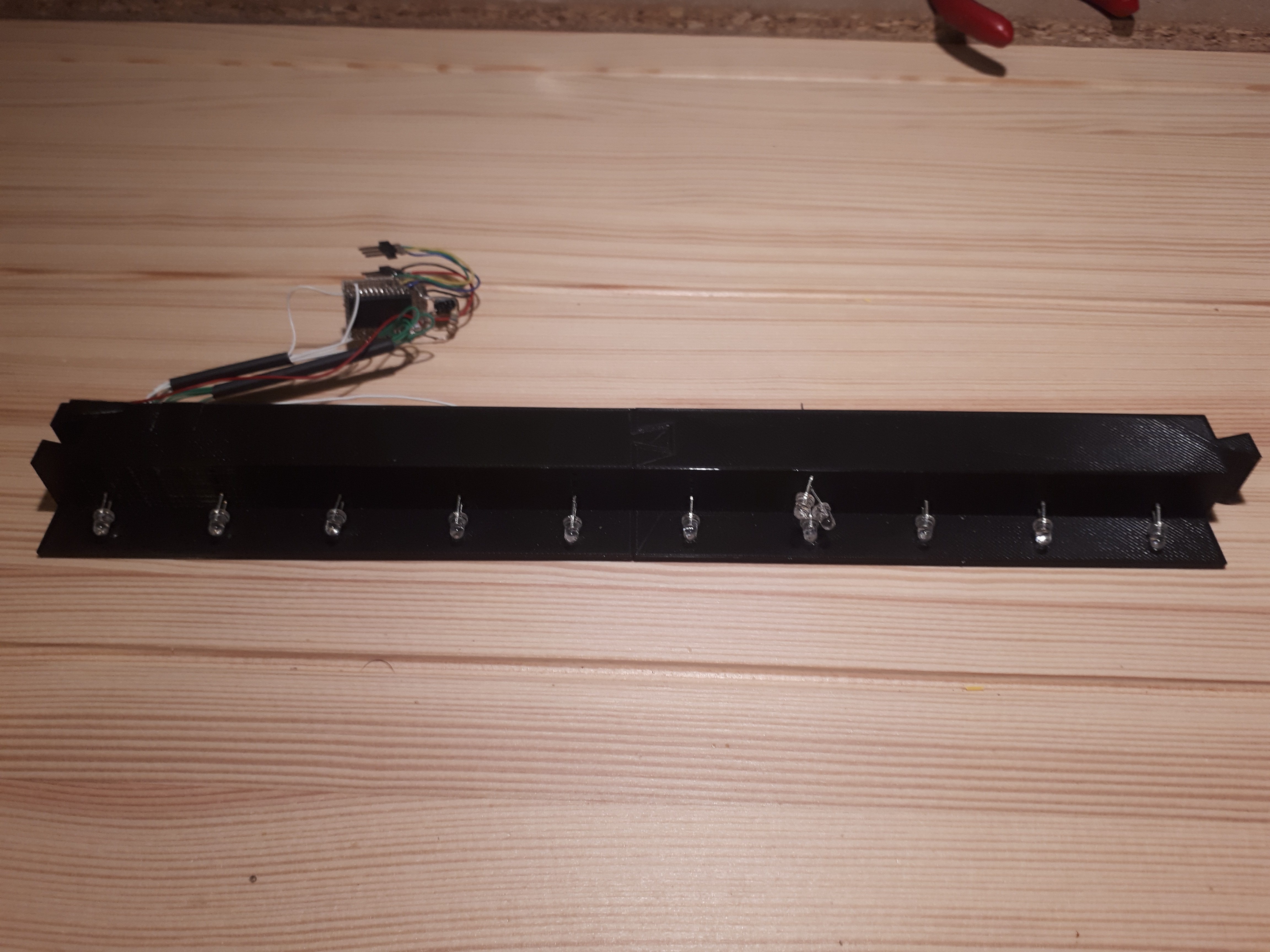
Here are 2 of my LED frame elements plugged in. I added the IR LED and the driving circuit.
I only added 1 LED per line (except on the seventh one, there are 3) because it's enough for the first frame size I want to build.
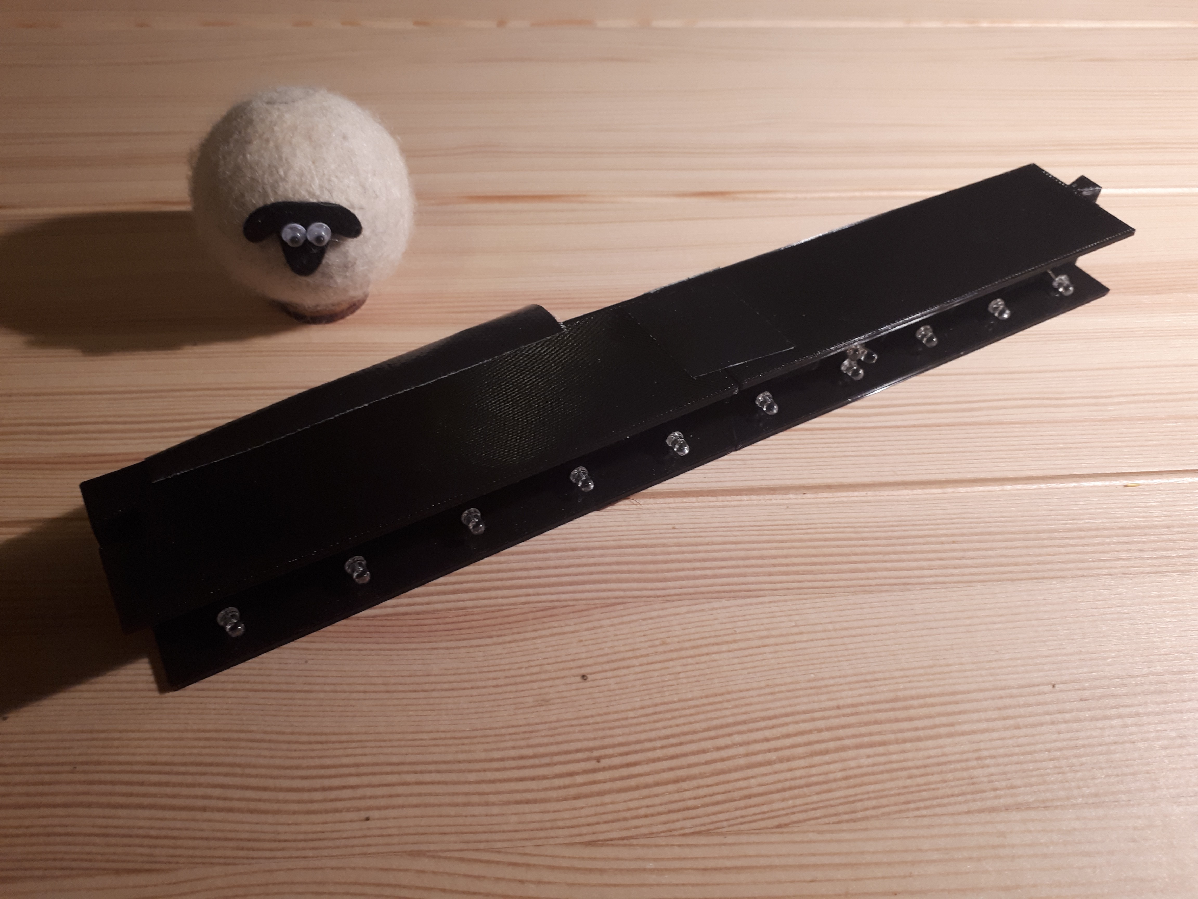
I also drew a roof for the element to hide the wires and circuit.
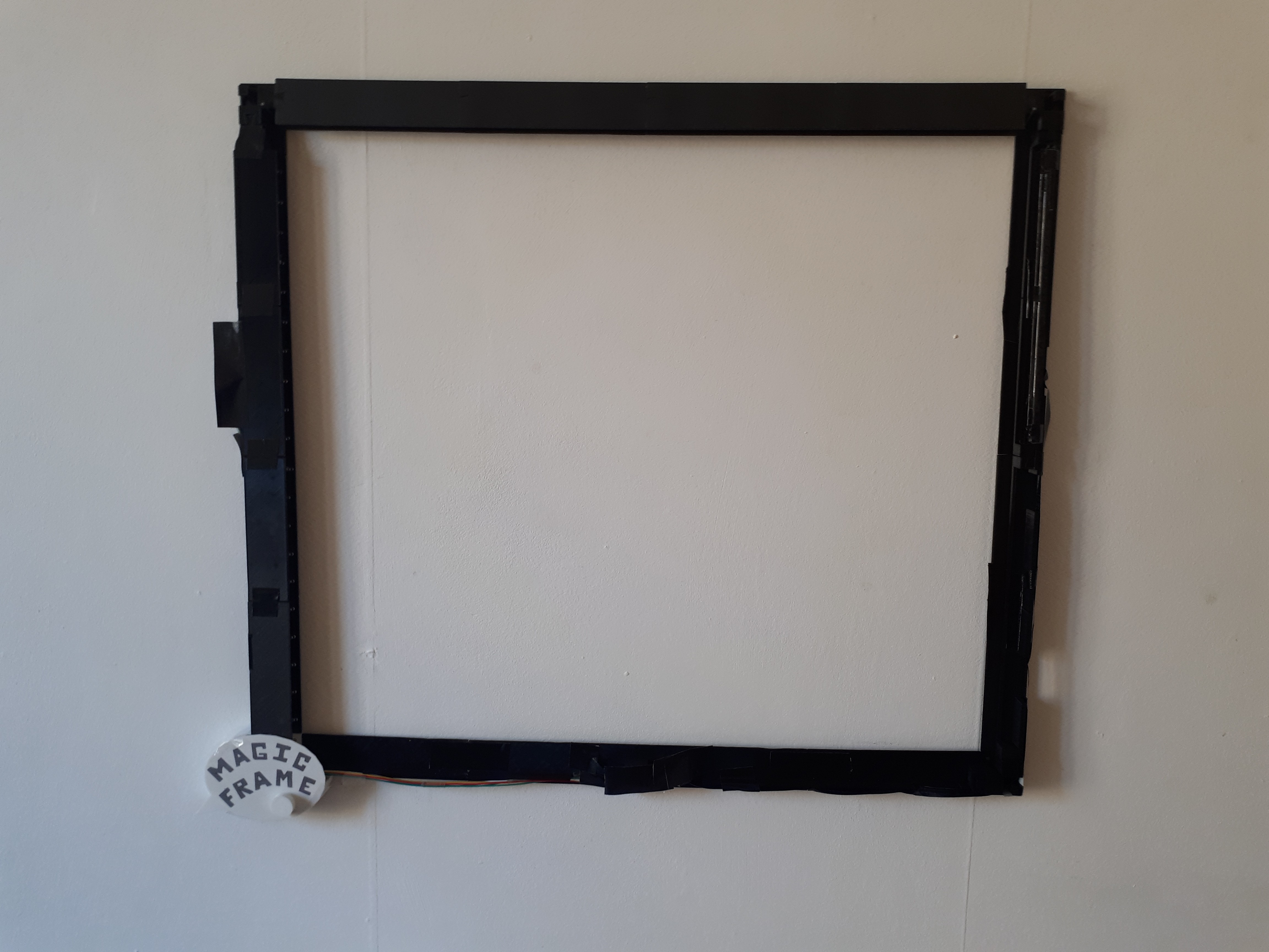
And now, the frame complete. There are actually only 4 elements at the top and bottom, but they are a bit larger.
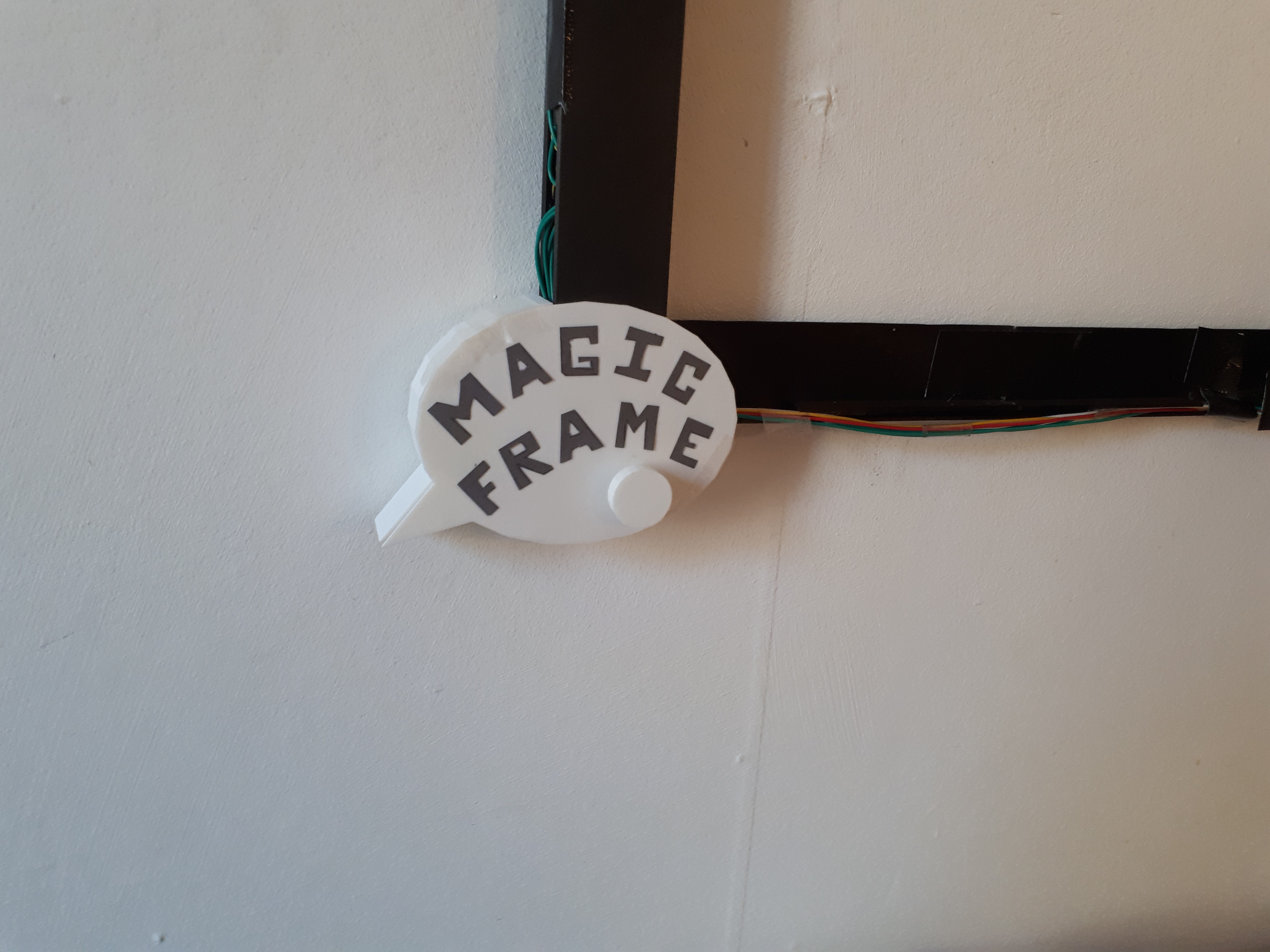
We can see the round rotary button under the word frame. You can increase or reduce the CIS's sensitivity with it.
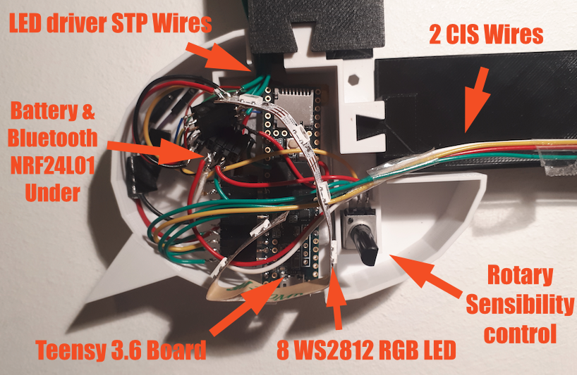
I am really sorry... This assembly is a mess!
That's one of the reasons why I've I immediately started to drawing a Magic Frame V3 :-p
Discussions
Become a Hackaday.io Member
Create an account to leave a comment. Already have an account? Log In.