 jean.perardel
The idea is to build an adaptable frame inspired by a jigsaw puzzle. Any size screen can be made just by adding more elements and by increasing the infrared LED power.
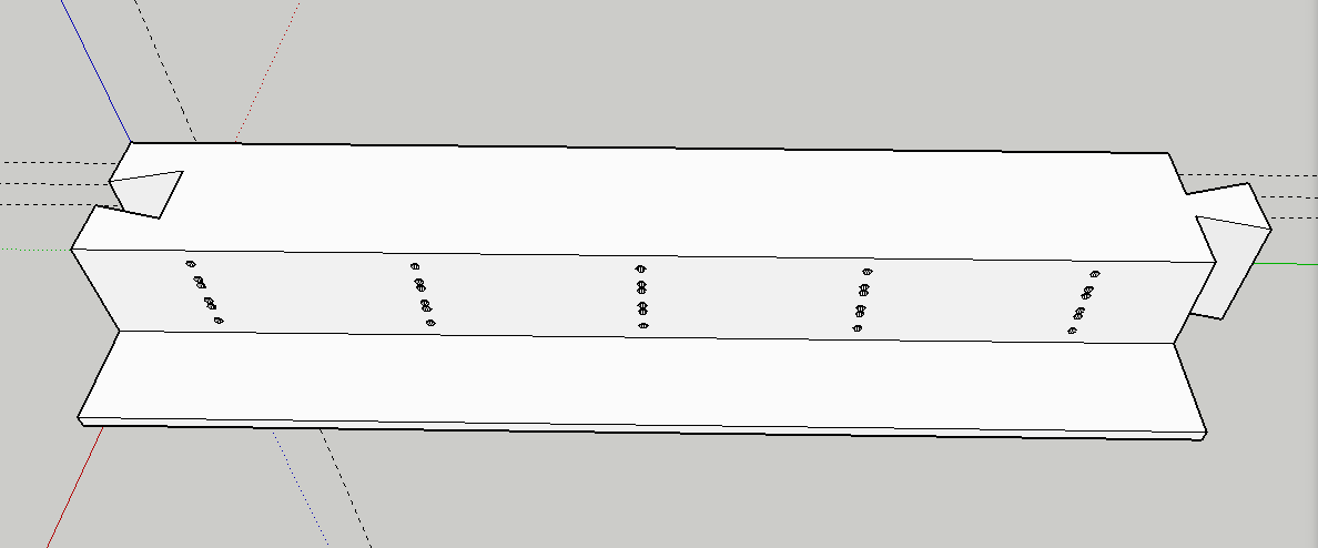
Here we have a "LED element" ready for 3D print. Several elements can be plugged into each other to create two emitting frames. The 5 small holes lines are for the LEDs. You can fit 3 LED per line to increase the emitting angle and the power. So this element can have 15 LED in total but it's only a 5 LED detection.
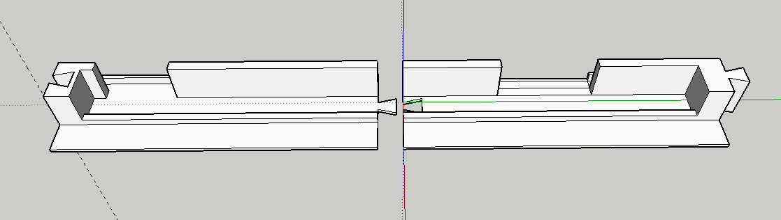
Here is a CIS element. As it's 26cm (10.2inch) large, It's printed in two parts to fit into an Ultimaker 2.
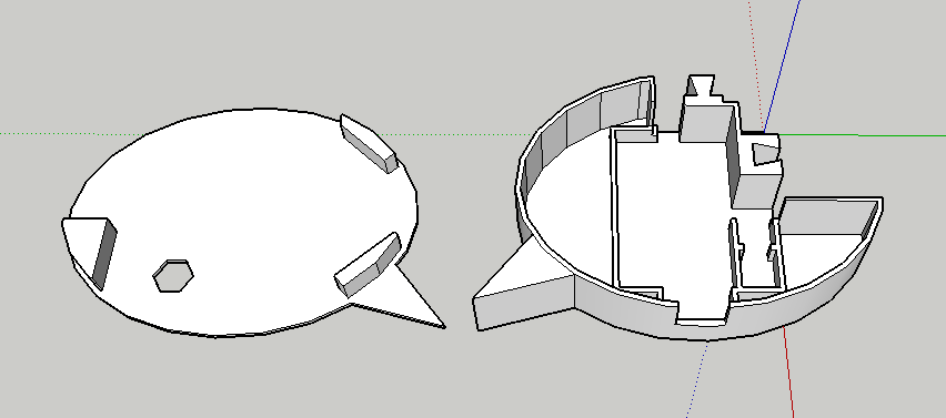
The corner of the frame to hold the structure and insert a screw for a wall mounted use.
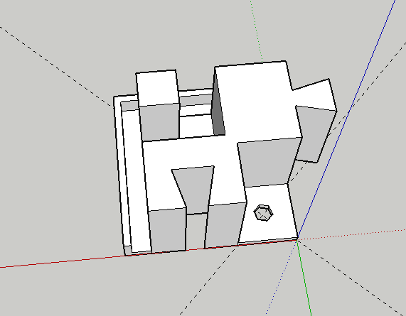
The last corner integrates the control board with most of the elements :
- A battery for wireless autonomous application
- The Teensy 3.6 control board
- A rotary going through the hole. It controls the sensitivity of the CIS sensor.
- 6 WS2812 RGB LED. As this element is printed in white. The LED gives a color to all of the enclosure. It will also help with calibrating.
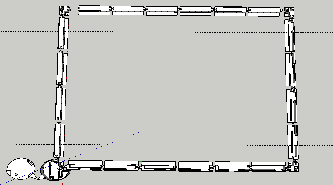
Here is the frame with all the elements. At left and at the top, we have 10 LED elements so 50 LED. At the bottom and on the right we have 6 CIS sensors.
This will make an almost perfect multitouch screen!
Discussions
Become a Hackaday.io Member
Create an account to leave a comment. Already have an account? Log In.