deʃhipu
-
Trinket M0 TFT — Mirrors, how do they work?
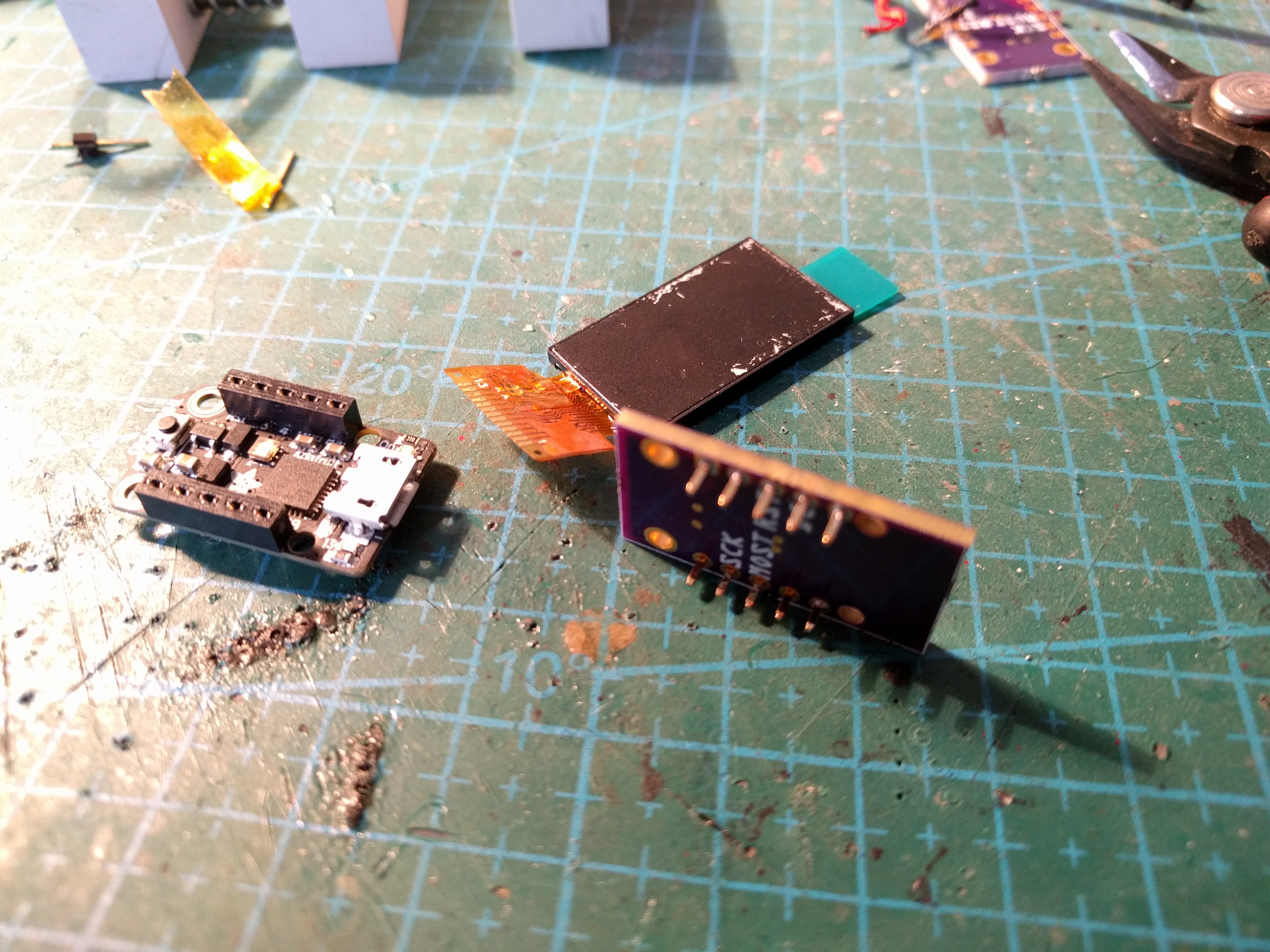
09/12/2017 at 15:43 • 0 commentsThe first of the PCBs I ordered for the #Trinket M0 TFT just came, and I started assembling it:
![]()
I can get a really low profile with the narrow headers and with male headers that have the plastic removed, so this is nice. There is however a slight problem. Even though the display is the only component that goes onto that PCB, I still managed to get it wrong: I used a mirrored footprint, copied from my previous design that had the connector on the underside of the board. But this board has the connector on the top, so it's rotated 180°. And it's too far from the other edge of the PCB for me to just rotate the whole display and use it like that.
And of course, I used the same connector design in the next two versions that I ordered, so they are also going to be wrong. So I quickly went and ordered a fixed version:
![]()
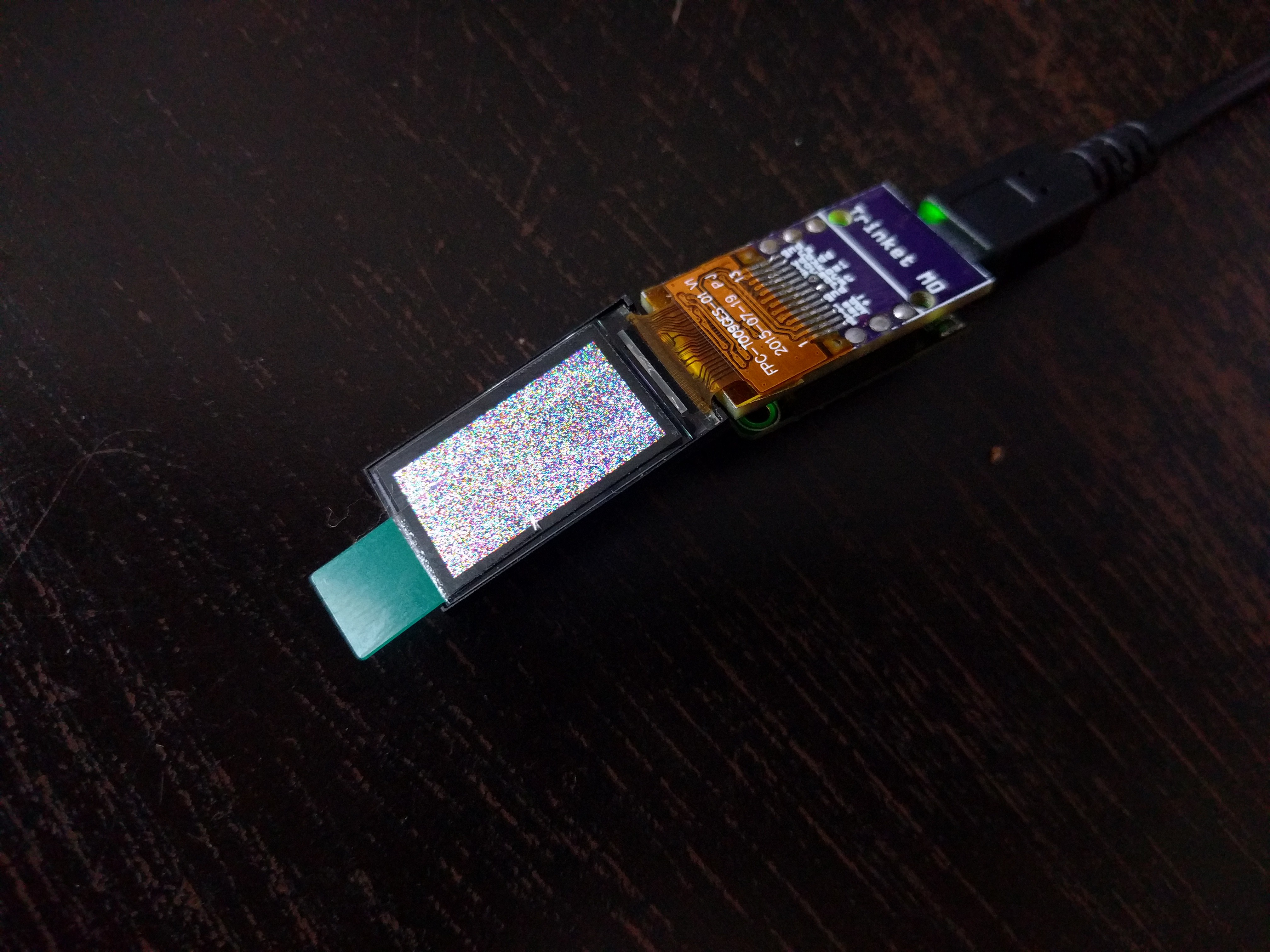
Even the routing was simpler with the mirrored display. I ordered this one with Super-Swift service, so hopefully I will have it this month. In the mean time, I still soldered one display to the board I have, to make sure there are no further surprises. It works as expected:
![]()
-
World Changing
09/07/2017 at 16:44 • 0 commentsHow will this project change the world? Probably very little. For one, in the new world there will be the shields available for people to use in their projects — so it will be slightly easier to start, slightly easier to build something with a display or buttons, and maybe even slightly easier to learn something new about electronics. There will also be a new version of the author of this project, with slightly more experience, possibly using that experience to build further projects. The world will also be slightly more polluted, the distribution of wealth will shift minimally, and so on.
So is this project world-changing? Definitely! Will you notice the change? Only if you are paying attention. Will it matter? It will to me, and perhaps a bunch of people who want those shields.
-
The Challenges
09/06/2017 at 21:14 • 0 commentsWell, there are two main challenges when designing a shield for the trinket: the lack of real estate on the board, and the limited number of available pins. Those are amplified with the limitations of manual soldering, the minimal specs of common PCB manufacturers, the available packages of the chips to be used, and the budget limits.
For instance, if I wanted to make a shield with a LED matrix on it, my first choice would be the HT16K33 chip that Adafruit uses in their backpacks. However, that chip is easily larger than the Trinket itself! So instead I would need to look for something smaller, possibly in a QFN package, like the IS31FL3728. I will also need to choose chips that use the I²C or SPI bus, because there can be multiple devices on those, or otherwise choose solutions that minimize the number of pins used, like using the ADC to read the states of buttons connected to different resistors.
Connectors are going to be a problem, since most of them have huge 2.54mm pitch through-hole pins. The solution for this is to use SMD versions of those connectors whenever possible, and use of smaller connectors. For instance, for the PWM shield, I'm going to use 1.27mm pitch connectors, compatible with the sub-micro servos.
Finally, if nothing else works, I can grow sideways. making the shield more square, with room for the connectors on the sides. But that is the last resort.
-
Usage Concept
09/06/2017 at 03:19 • 0 commentsThe following image illustrates how this project might be used:
![]()
Yes, you put the shield on top of the development board. If you feel particularly adventurous, you could also put on the bottom, although that won't probably work particularly well with displays.