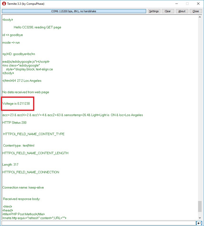
ADC initialization (main.c):
//ADC ####ADC####ADC####ADC####ADC####ADC####ADC##############################################################
    //
    // Pinmux for the selected ADC input pin
    //
    MAP_PinTypeADC(PIN_60,PIN_MODE_255);
    uiChannel = ADC_CH_3;
    //
    // Configure ADC timer which is used to timestamp the ADC data samples
    //
    MAP_ADCTimerConfig(ADC_BASE,2^17);
    //
    // Enable ADC timer which is used to timestamp the ADC data samples
    //
    MAP_ADCTimerEnable(ADC_BASE);
    //
    // Enable ADC module
    //
    MAP_ADCEnable(ADC_BASE);
    //
    // Enable ADC channel
    //
    MAP_ADCChannelEnable(ADC_BASE, uiChannel);
Inside the man.c while{ } loop:
//ADC  ##########################################################################################################
    	while(uiIndex < NO_OF_SAMPLES + 4)
    	{
    		if(MAP_ADCFIFOLvlGet(ADC_BASE, uiChannel))//If a sample is ready
    		{
    			ulSample = MAP_ADCFIFORead(ADC_BASE, uiChannel);//Read the sample
    			pulAdcSamples[uiIndex++] = ulSample;//Load the sample into an array
    		}
    	}
    	//MAP_ADCChannelDisable(ADC_BASE, uiChannel);//
    	uiIndex = 0;
    	ADCsum = 0;
    	while(uiIndex < NO_OF_SAMPLES + 4)
    	{
    		//UART_PRINT("\n\rVoltage is %f\n\r",(((float)((pulAdcSamples[4+uiIndex] >> 2 ) & 0x0FFF))*1.4)/4096);
    		ADCsum = ADCsum + pulAdcSamples[uiIndex];
    		uiIndex++;
    	}
    	ADCsum = ADCsum / (NO_OF_SAMPLES + 4);
    	UART_PRINT("\n\rVoltage is %f\n\r",((ADCsum >> 2 ) & 0x0FFF)*1.4/4096);
    	//UART_PRINT("\n\rVoltage is %f\n\r",((pulAdcSamples[4] >> 2 ) & 0x0FFF)*1.4/4096);
    	UART_PRINT("\n\r");
//################################################################################################################
 Roman
Roman
Discussions
Become a Hackaday.io Member
Create an account to leave a comment. Already have an account? Log In.