When I started this project, I had an inkling that the fingerprint reader spoke USB. To verify this, I popped the board out of my computer and tacked on a few test wires:
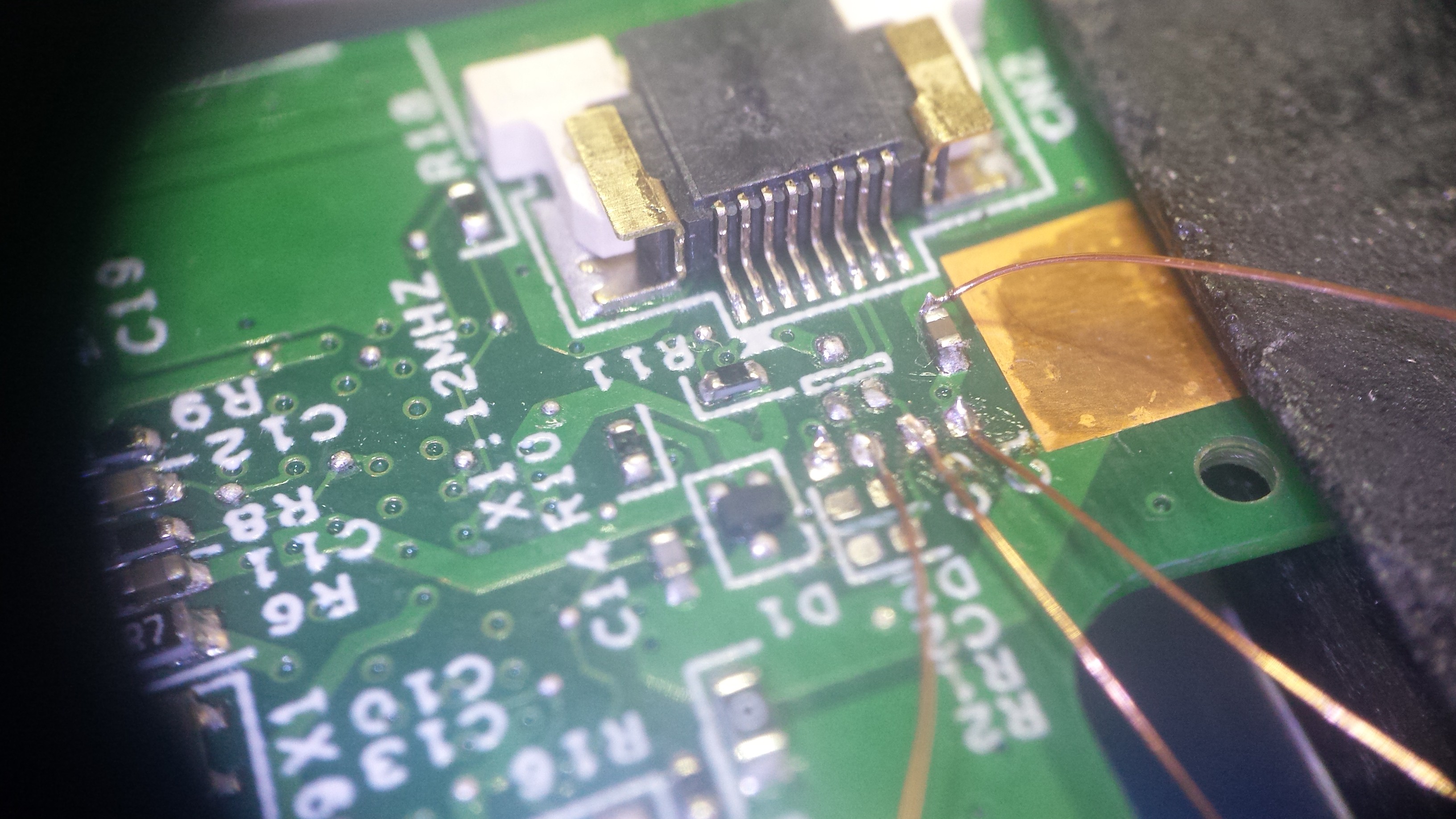 [above: 10x loupe photo of the fingerprint reader PCB showing a few test wires]
I labelled the wires according to position on the FFC header, snaked them through the fingerprint reader cutout, and reassembled the computer so I could 'scope 'em:
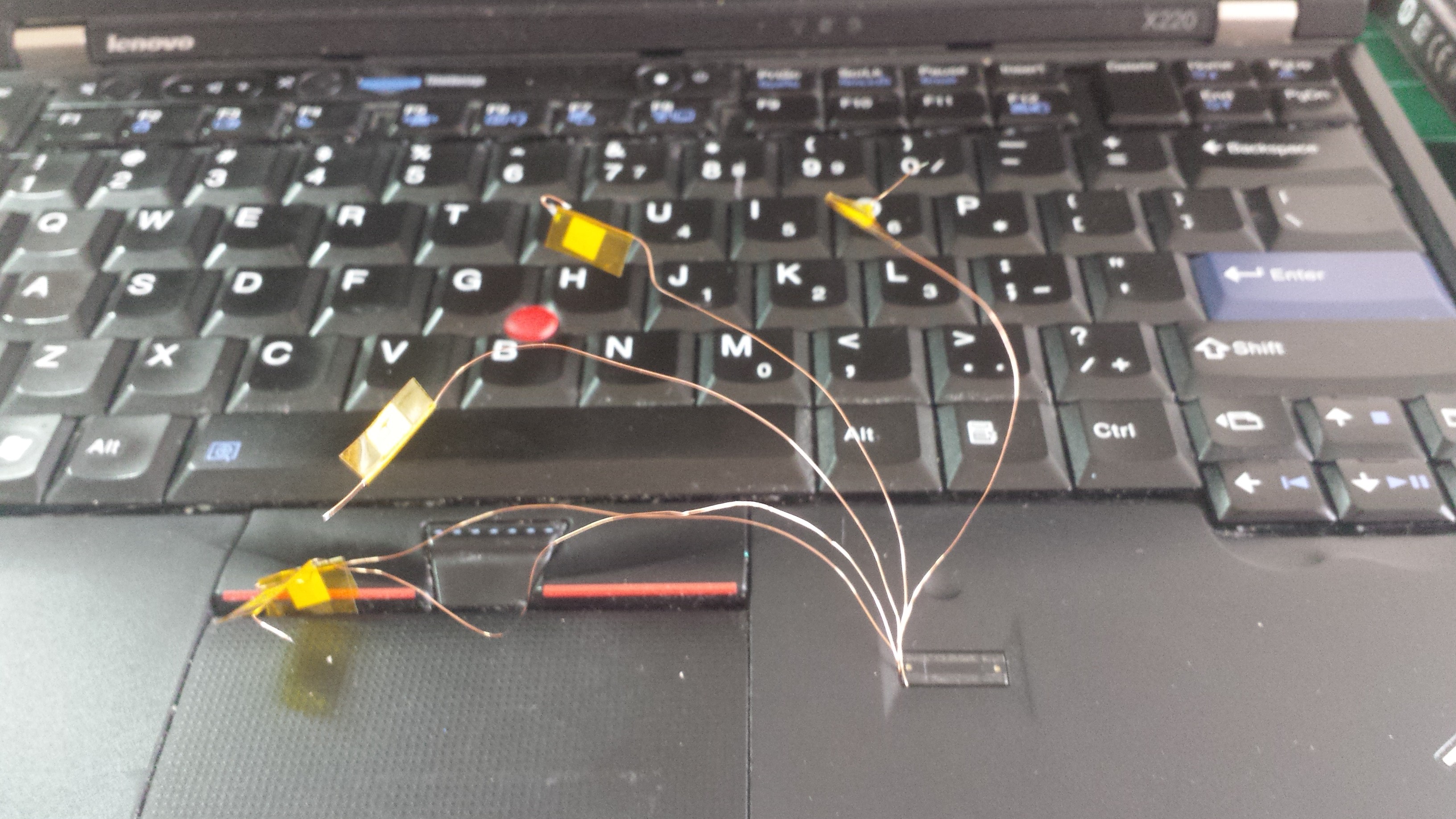 [above: testing potential USB traces, prior to getting over my fear of disassembling my laptop without disconnecting power/battery]
This didn't tell me much, beyond suggesting that the fingerprint reader didn't require +5VDC. Most of the wires seemed to be +3.3VDC or ground, but a few appeared to have some interesting signals on them. I decided to butcher the fingerprint board and make an FFC header breakout so I could convince myself everything worked:
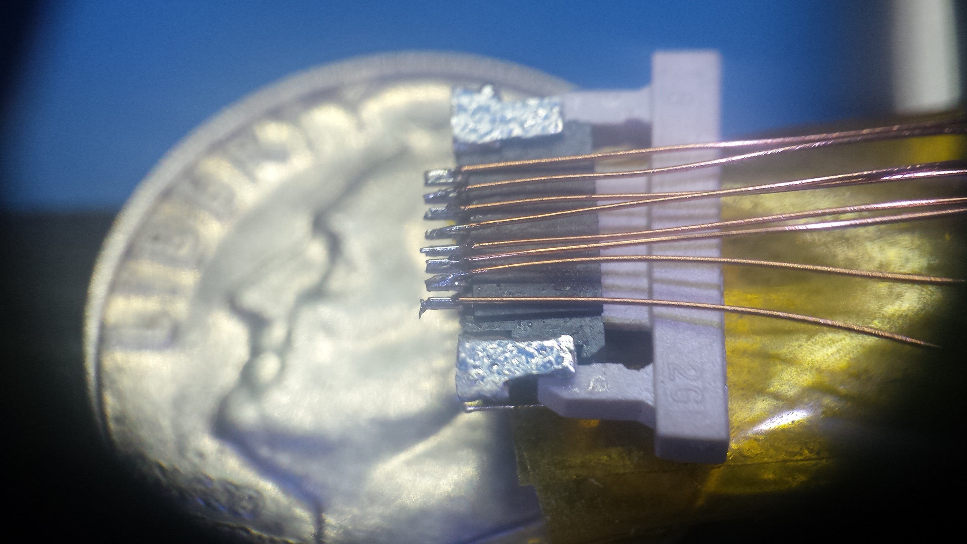 [above: another 10x loupe shot confirming that breakout boards are for suckers]
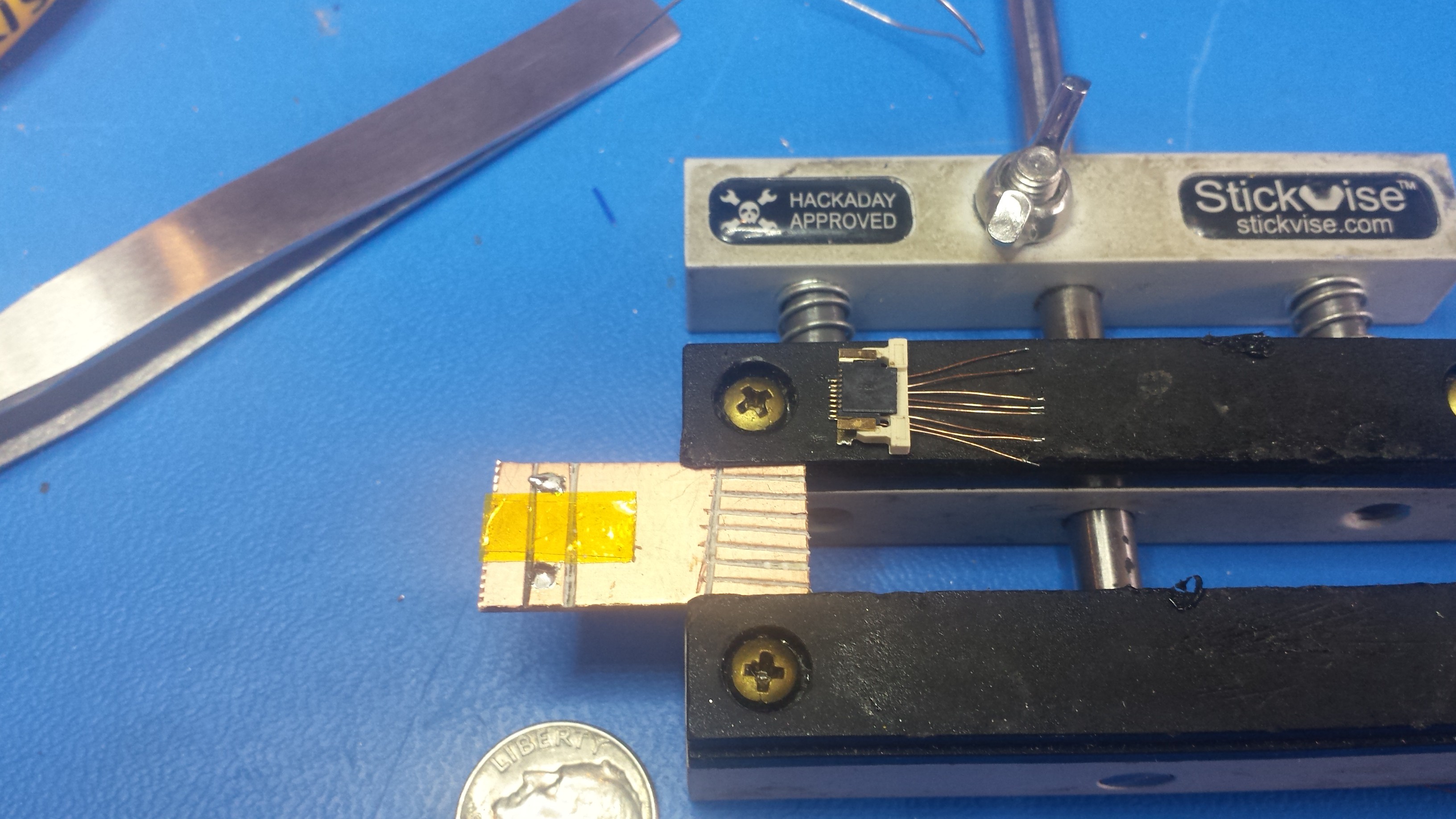 [above: always looking for an excuse to carve FR4...]
Eventually, I bodged together a breakout and located the two USB data pins. I tested everything using a hacked-apart ST-LINK from an STM32F0 Discovery Board to program a #NeuroBytes Interneuron:
 [above: an Interneuron connected via st-util (hence the green light on the Discovery board half). The +3.3VDC supply voltage didn't cause any issues for the ST-LINK, but it did mean that the Interneuron's LED was quite dim.]
So... if you want a free 3.3VDC USB port instead of your Thinkpad's fingerprint reader, here's the pinout:
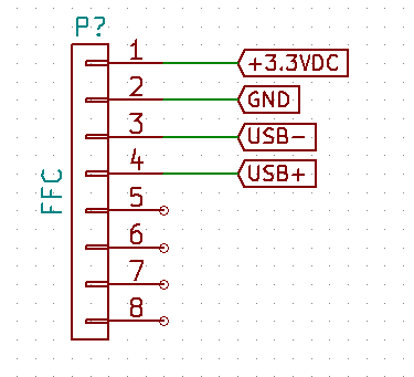 [above: FFC USB pinout, if the cable has conductors exposed on the top and enters from the left.]
 zakqwy
Discussions
Become a Hackaday.io Member
Create an account to leave a comment. Already have an account? Log In.