Programmer Design Options
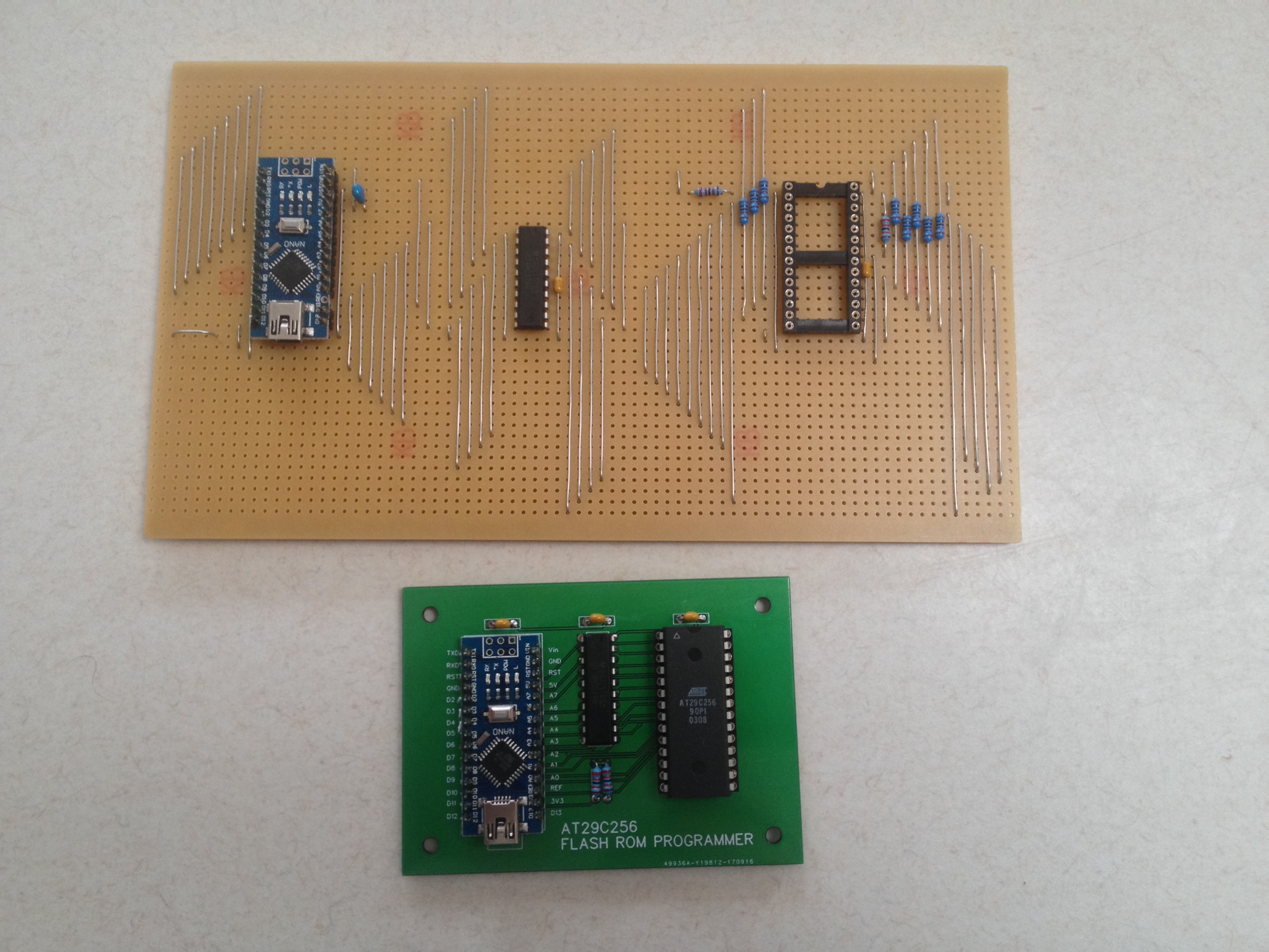
Strip-board works well (I use A$8 41 x 144 board), but I did look at using a mini-Mega2560:

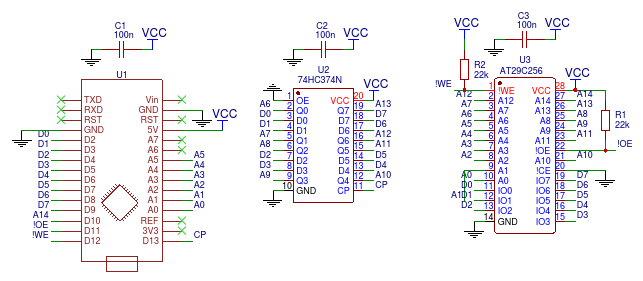
I used an on-board Arduino Nano as they are cheap (and I have a couple of them lying around) and they provide serial and power.
But usually not as many pins as you would like. So some way of expanding the number of available pins.
The options include serial (74HC595), I2C, SPI but this time chose to multiplex the databus and latch (clock) the high address using a 74HC374. This approach will be much faster than the others listed.
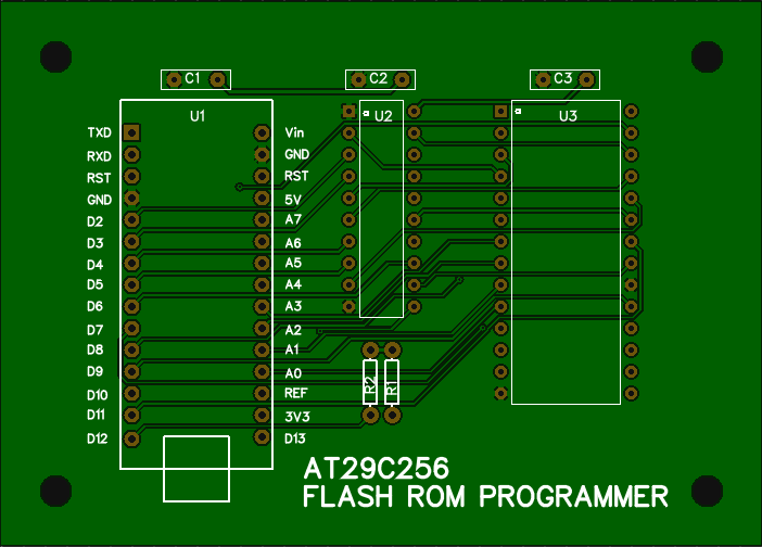
Here is my strip-board design:
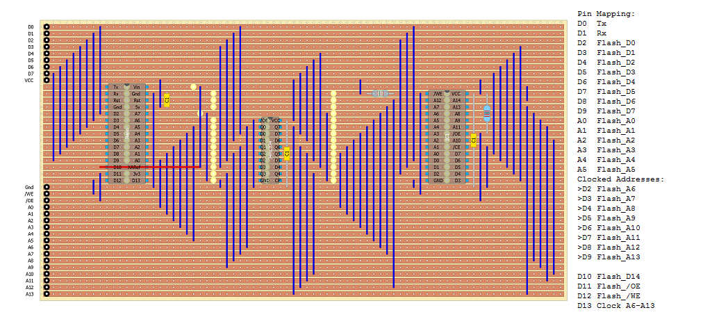
The red line is to remind me to not solder a pit for the ARef so I can get D10 to the other side of the board without a wire jumper.
As you can see, the databus uses D2-D9 which is a bit of a programming headache, I cannot use TX/RX (i.e. D0/D1) as I want to also use serial.
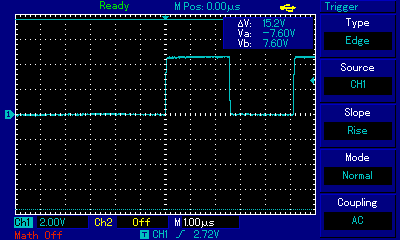
In the final design I added 1k resistors to the databus between the Arduino and the AT29C256 to protect the AT29C256 from bus conflicts due to bad programming. The problem is that the Nano can easily provide enough current to burn the AT29C256 output buffers.
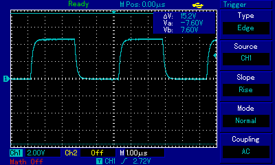
Adding these resistors slows down the databus, before:
and after:
Traps
There is bug in the delayMicroseconds() procedure:
"delayMicroseconds(1)" is approximately 120ns:
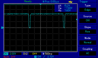
"delayMicroseconds(2)" is approximately 1us:
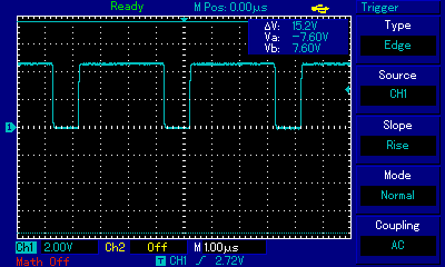
This was important as the resistors slowed down the databus.
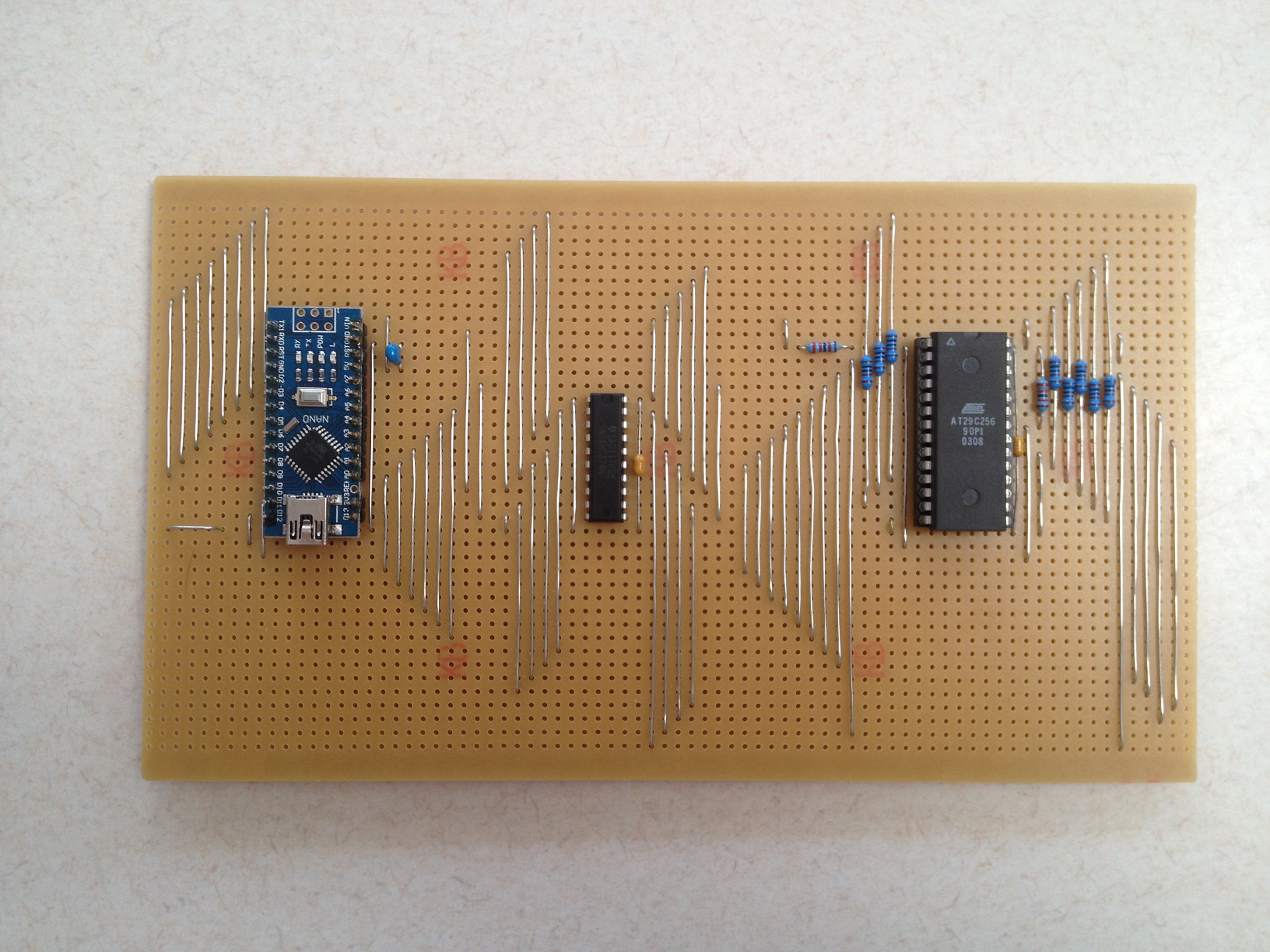
Here is my final board:
Programming the Flash Chip
I wrote a simple Arduino sketch, here is an example run:
Welcome to the AT19C256 FLASH Programmer V1.0
First read the FLASH (y/n)?
0000: 00 01 02 03
0004: 04 05 06 07
0008: 08 09 0A 0B
000C: 0C 0D 0E 0F
0010: F0 F1 F2 F3
0014: F4 F5 F6 F7
0018: F8 F9 FA FB
001C: FC FD FE FF
0020: 00 01 20 30
0024: 40 50 60 70
0028: 80 90 A0 B0
002C: C0 D0 E0 F0
0030: 0F 1F 2F 3F
0034: 4F 5F 6F 7F
0038: 8F 9F AF BF
003C: CF DF EF FF
FLASH read done.
Write the FLASH (y/n)?
FLASH write done.
Verify (read) the FLASH (y/n)?
0000: 00|00 00|00 00|00 00|00
0004: FF|FF FF|FF FF|FF FF|FF
0008: 00|00 00|00 00|00 00|00
000C: FF|FF FF|FF FF|FF FF|FF
0010: 00|00 00|00 00|00 00|00
0014: FF|FF FF|FF FF|FF FF|FF
0018: 00|00 00|00 00|00 00|00
001C: FF|FF FF|FF FF|FF FF|FF
0020: 00|00 00|00 00|00 00|00
0024: FF|FF FF|FF FF|FF FF|FF
0028: 00|00 00|00 00|00 00|00
002C: FF|FF FF|FF FF|FF FF|FF
0030: 00|00 00|00 00|00 00|00
0034: FF|FF FF|FF FF|FF FF|FF
0038: 00|00 00|00 00|00 00|00
003C: FF|FF FF|FF FF|FF FF|FF
FLASH verify done.
FLASH Programmer done.
How does it Work
The code to download to the Flash is written in the sketch (pretty primitive I know!).
One option I want to look at is cutting and pasting the code into the terminal window.
The code is limited to about 26kB because that is all that is free in the Nano after uploading the sketch.
This means, to program a full 32kB, two passes are required.
At the moment, all this is hard coded in the sketch.
So most of this project is about code development.
AlanX
 agp.cooper
 Saabman
 Bruce Land
 Muth
Muth
 lion mclionhead