 Rupert Young
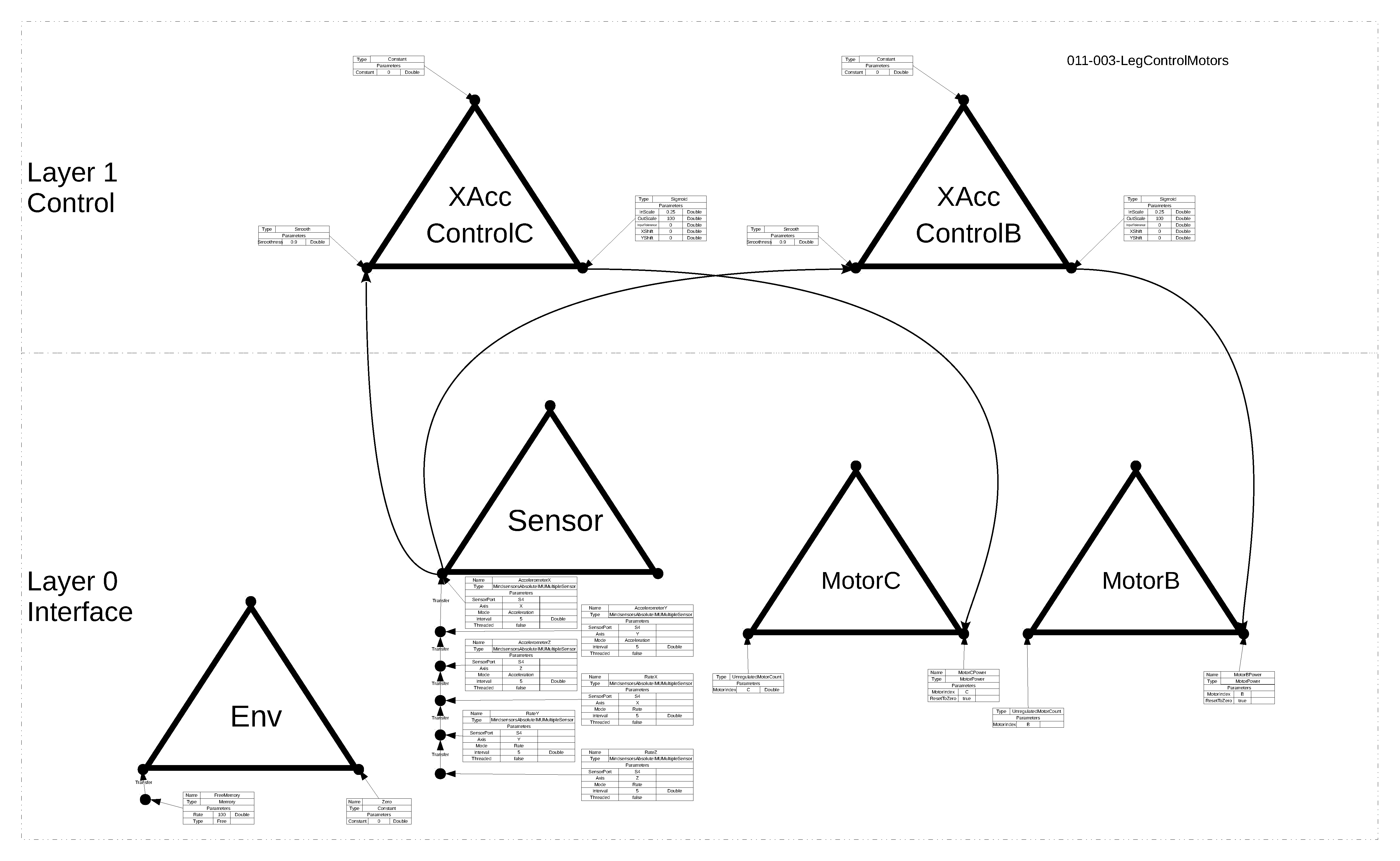
The image below is the design layout of the leg system that balances on the basis of two motorised joints. This corresponds to the ODG file 011-003-LegControlMotors.odg added to the project files.
There are two control systems both of which control the acceleromter X value at a goal reference value. The output from each affects a different motor, to a degree that is a function of the balance error.
Discussions
Become a Hackaday.io Member
Create an account to leave a comment. Already have an account? Log In.