-
Software Design
09/16/2017 at 14:21 • 0 commentsWhen the ESP8266 starts, and this could be from a cold start like a power fail or a wakeup from its deep sleep mode, it attempts to connect to wifi. If it fails, or was never configured, it creates a captive WiFi portal that allows configuration of WiFi SSID and password, current clock position, NTP server, time change information, and some advanced settings.
After connecting to WiFI it makes an NTP request and computes both the offset and network delay. The offset is used to adjust the RTC only the offset is greater than a threshold and if the network delay is within 1 standard deviation from the last 7 or 8 requests. The last 8 offsets that were used to adjust the RTC are saved and used to compute the drift in parts per million of the RTC. This is used between NTP requests to help keep the RTC, and the cock, ticking at the correct time.
Next the current time is read from the RTC and converted to a clock position. Since most analog clocks only have a 12 hour face there are only 43200 possible unique hand positions so we represent the position of the analog clock as an unsigned integer between 0, midnight/noon, and 43199, 11:59:59/23:59:59. The current clock position is also read from the ATTiny85 and an adjustment is computed and sent back to the ATTiny85.
The ESP8266 then enters its lowest power sleep mode, deep sleep, where only a wakeup timer and the 512 bytes of memory that we use to store the NTP samples are powered.
Setting the RTC within milliseconds is a challenge since it’s the time it keeps is in 1 second values. The key is that when you write the seconds value to the RTC it synchronizes it 1Hz square wave output to that moment. The specific verbiage in the DS3231 data sheet is “The 1Hz square-wave output, if enabled, transitions high 500ms after the seconds data transfer, provided the oscillator is already running.” This makes the falling edge the start of each second. So by using the offset from NTP and coordinating when to set the time to be where NTP says the second should start syncs the RTC within a milliseconds.
The other RTC trick is that when we read the time for the origin timestamp of an NTP request we wait for the falling edge of the square wave first. Since this is a second boundary the NTP timestamp will be with zero fraction value.
One area thats still a work in progress is deciding how long to wait between NTP polls. The longer this is the less overall power will be used and the longer the batteries will last. Currently, and this is a work in progress, I’m using samples obtained since the previous adjustment to compute an estimated drift. This is then used to compute how long at the estimated drift rate it would take the clock to drift by the offset threshold.
-
Hardware Design
09/16/2017 at 14:20 • 0 commentsI ran a number of experiments both attempting to directly drive the clock from micro-controller I/O pins and using an H-bridge type circuits. Testing driving directly meant using 3.3v or 5v depending on what micro-controller I was using at the time and I was concerned with using two much power since this was designed to be used with a 1.5v battery. I found a small low power motor controller (DRV8838) that supported motor voltages including 1.5v and decided to use that.
To control the DRV8838 I chose an ATTiny85 to manage ticking the clock as its small, fairly low power, has an internal oscillator, and has exactly enough I/O pins when the reset pin is converted to an I/O pin. We need six I/O lines; three to control the DRV8838, one to receive the 1Hz signal for ticking and two for i2c communication.
I selected a DS3231 as a Real Time Clock (RTC) as its low power, has integrated temperature compensated crystal oscillator, supports a 1Hz square wave output, and has an i2c interface.
I chose an ESP8266 as the main controller to manage configuration and NTP synchronization as its a really cheap wifi module with a flash-able micro-controler and multiple I/O pins.
The way this works is that the ESP8266 wakes up at a configurable interval and makes a NTP request, if the computed offset is more than a threshold, I’m using 20ms currently, the RTC is updated using a method that aligns its second boundary to where NTP says it should be. The RTC is configured to output a square wave at 1Hz with the falling edge being the second boundary. This is connected to one of the ATTiny85’s interrupt pins and configured to interrupt on the falling edge waking the the ATTiny85 from sleep to tick the clock each second.
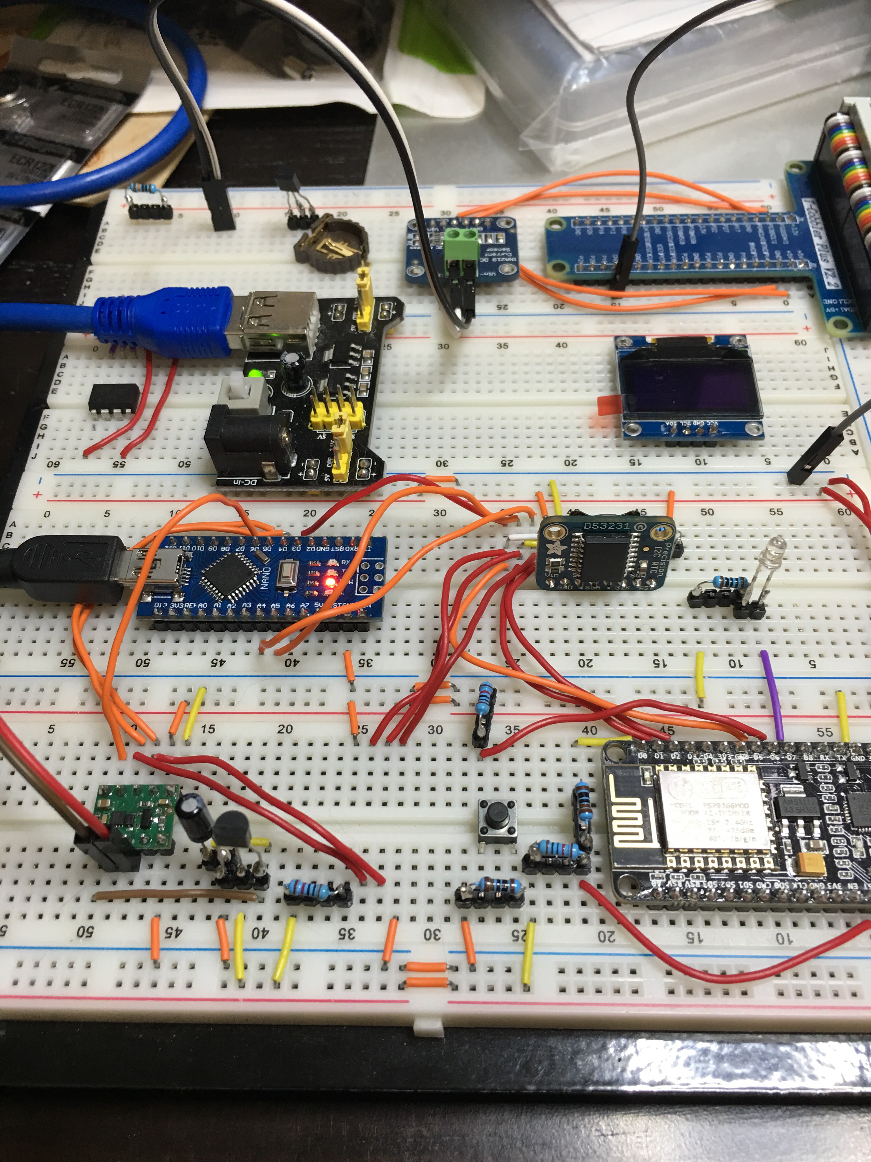
I assembled this on a solder less breadboard for testing and initial software development. In this early version I was using an Arduino Nano in place of the ATTiny85 for convenience.
-
Initial Research (March 2017)
09/16/2017 at 14:18 • 0 commentsInternet searches turned up quite a few clock projects. Many were digital and while interesting did not help much. Quite a few were complete custom clocks. I did find a few Analog Clock hacks.
I found two that was were similar to what I wanted: (http://hackaday.com/2015/11/19/a-networked-analog-clock/ and https://hackaday.io/project/16742-espclock.). The problem for me was I wanted battery operation and the ESP8266 cpu/wifi module uses 70 milli-amps on average - much too much for the battery powered device I wanted. Another interesting one I found was “Crazy Clock”: (https://hackaday.io/project/5880-crazy-clock). This remained lower power but had no network connectivity to keep the clock synched with an external time source. It did however had a really nice description on how standard quartz clock movements work. And another, "Lunchtime Clock": (http://www.instructables.com/id/Lunchtime-Clock/)). It uses a RealTime Clock module to keep accurate track of the correct time. This one also uses too much power and does not have network connectivity.
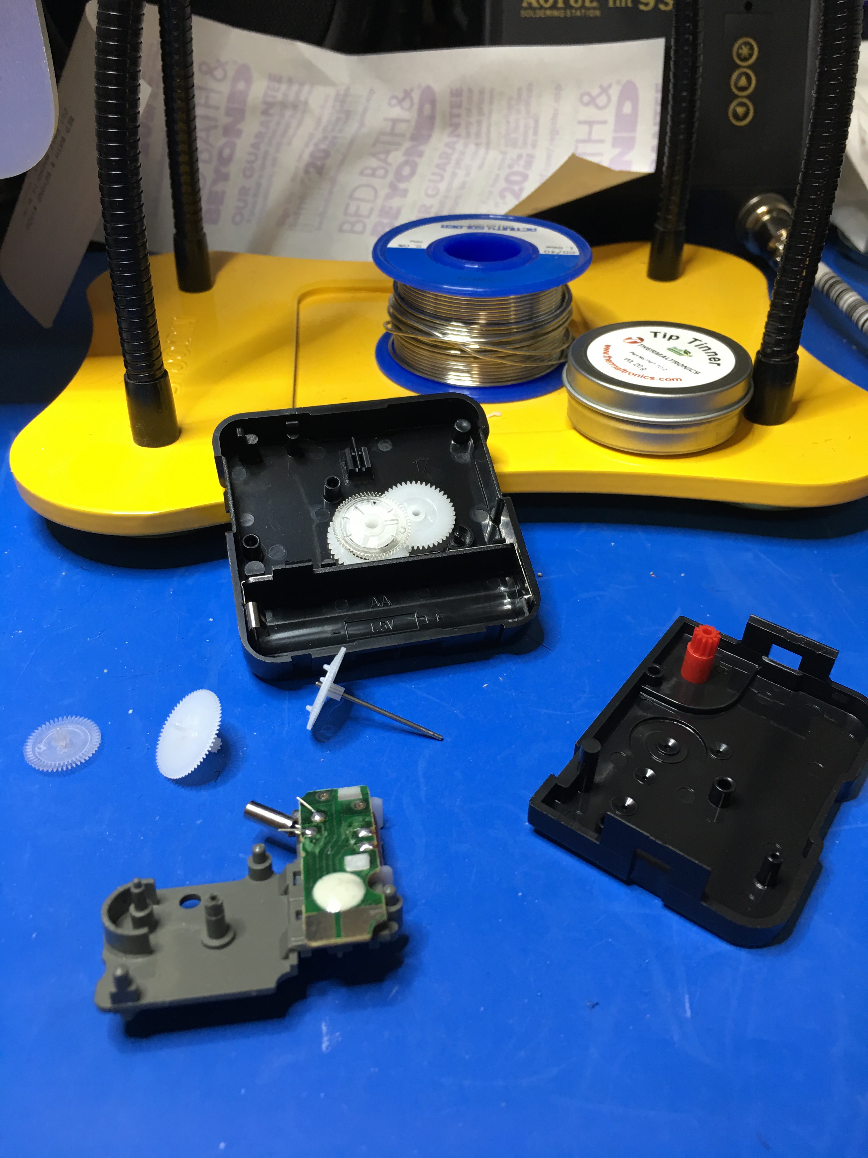
So I went shopping with the wife and bought two fairly cheap ($10) analog clocks and survived "the look" when I immediately disassembled them upon arriving home.
Most quartz clock movements use a Lavet type stepping motor to physically drive the clock hands. Driving one of these requires us to alternate polarity each second. This can be done with a half H-Bridge type of circuit.
 liebman
