I installed my new pcb for the smartphone remote control in my car:
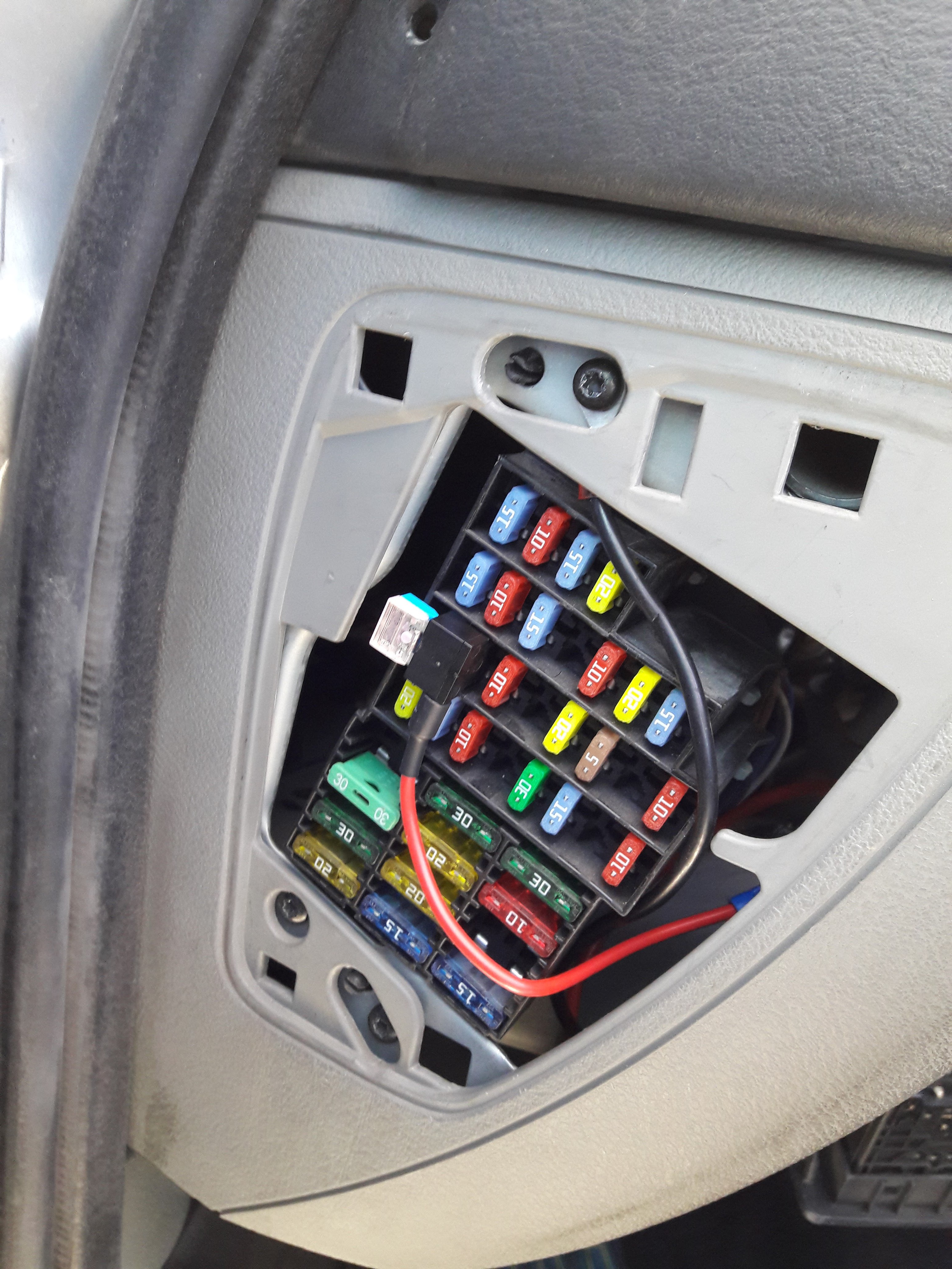
I added a 12V circuit from the car radio fuse:
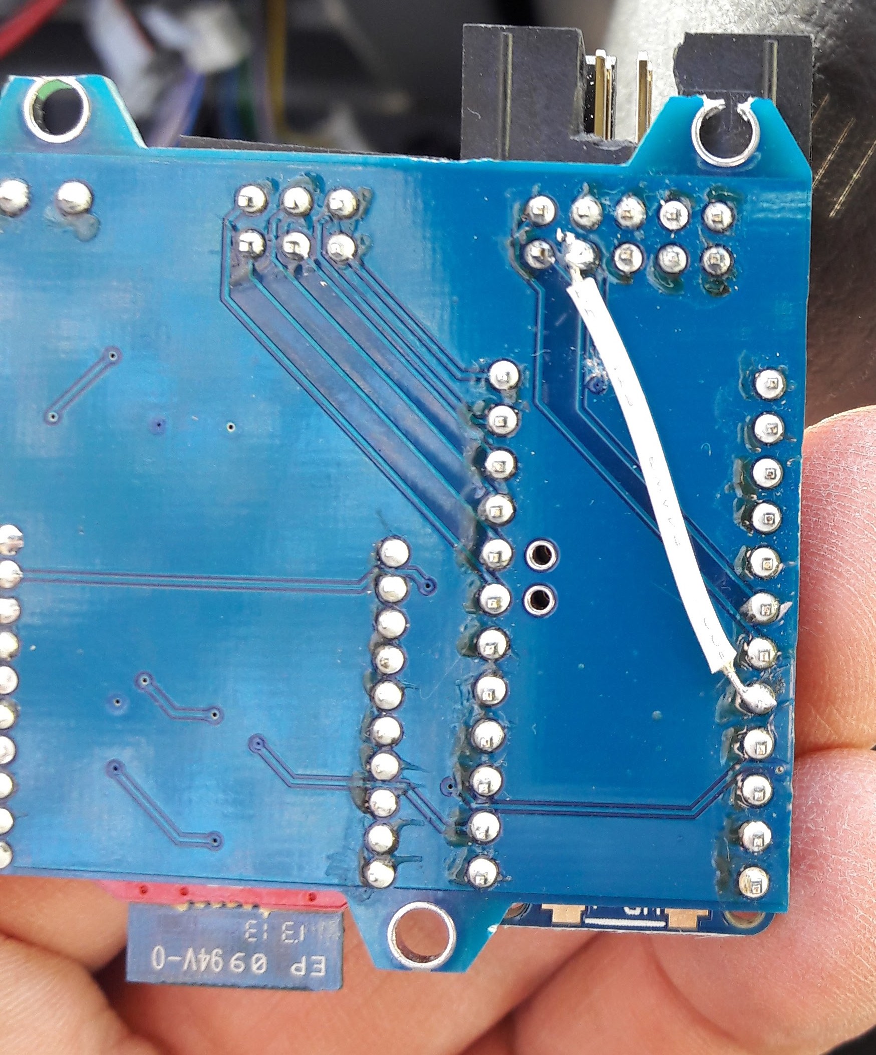
... bodged the D13 pin to D8 pin (the led on the trinket board might prevent the digital input from working properly)
and installed it in a small compartment near the fuse box:

(everything in wrapped with heat shrink tubing)
I had to modify the 10 pin header to insert the cable with a 180 degrees rotation and a small commit to github did the rest.
Everything is working so far and I added a task on Tasker to start the webradio app when it detect the bluetooth connection to the hid bluetooth remote control.
Discussions
Become a Hackaday.io Member
Create an account to leave a comment. Already have an account? Log In.