 Sky Carter
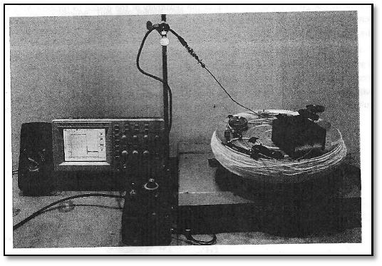
Figure 2 (Skyhunt): The Completed Ring-Laser Gyro. ^
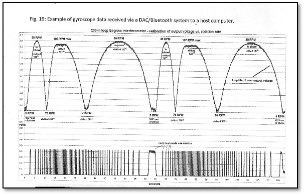
Figure 3 (Skyhunt): The Oscilloscope Results. ^
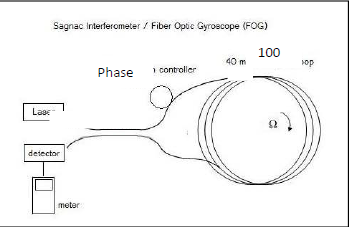
Block Diagram (Skyhunt)
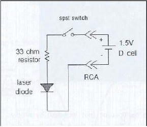
Laser Circuit (Skyhunt)
This circuit uses a current limiting resistor to lower the voltage more
suitable for the diode. The diode outputs ≈ 1mW @ 1300nm.
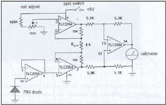
PIN Diode Circuit (Skyhunt)
This circuit uses a gain of 11 and a manual null adjust to zero out the output. This circuit is known as a "common mode rejection amplifier", which is used to reduce noise on the output. The Ouput could be displayed by either a Multimeter or an Oscilloscope.
Discussions
Become a Hackaday.io Member
Create an account to leave a comment. Already have an account? Log In.