Close
0%
0%

Thermoforming Machine Rebuild

A team of makers work to refurbish an old industrial thermoforming machine

Similar projects worth following
What happens when industrial machines grow old, break down, and are retired from production? Usually they become scrap metal, but sometimes they go to a bunch of makers who want to give it a second life. This is the story of an old Q-Vac thermoforming machine that we want to get back up and running.

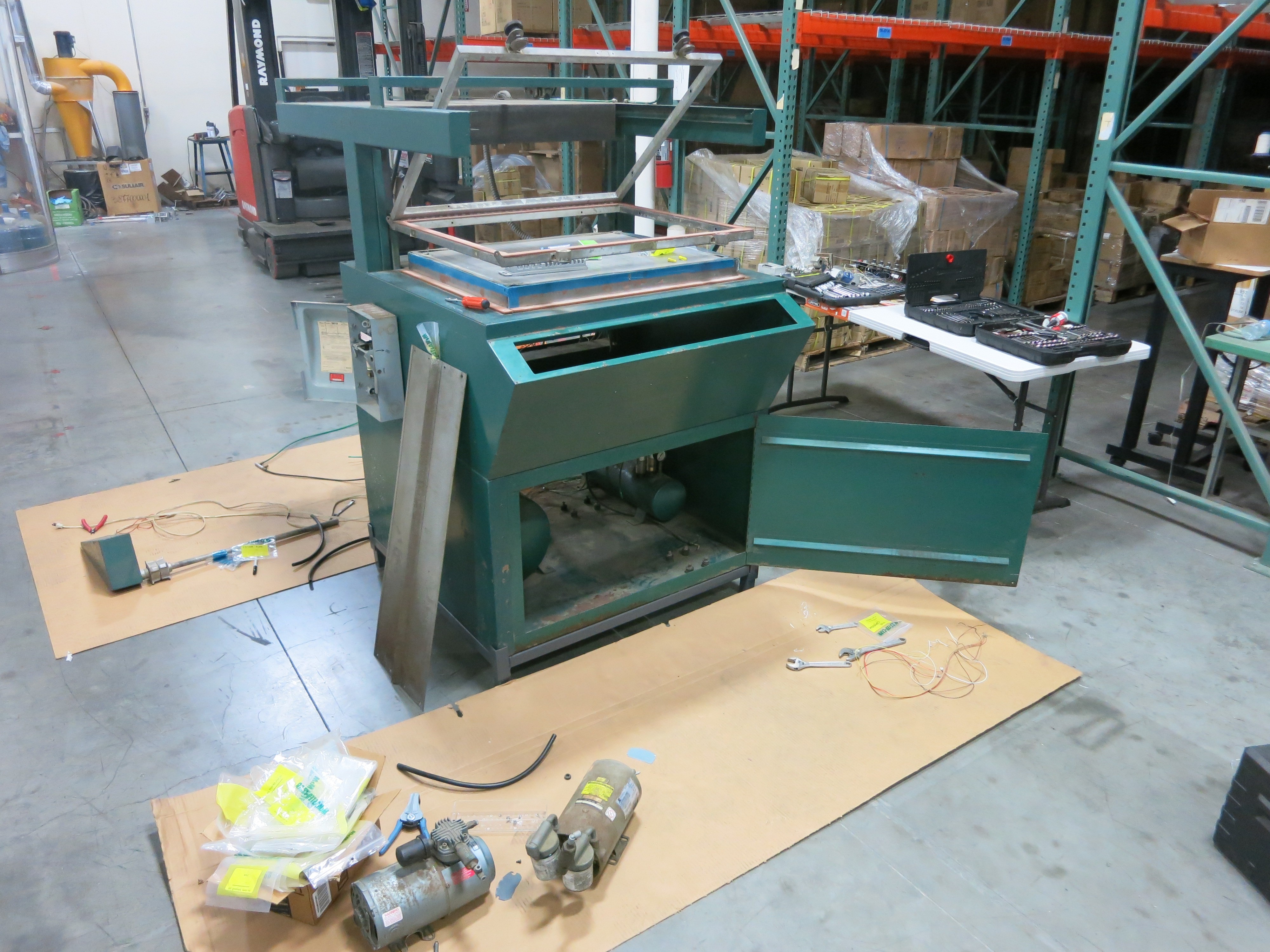
The machine was purchased in non-working condition. Inspection showed many signs of a long career possibly going as far back as the late 1970s. The "Q-VAC" name and logo still appears to be around today. Google pointed to their web site which lists a similar looking machine. The old machine here is likely the ancestor (or at least in the same family tree) as the current Q-VAC PC Series,.

Many components are clearly not original equipment. Given the highly modified status of the machine, it was decided it won't be worth the effort of trying to reverse-engineer decades of modifications from repairs and rebuilds. We'll rebuild it our way by tearing it down to fundamental components and build back up from there.

The goal is to get the machine up and running again in a manually-operated fashion. If it does start seeing significant use and operator time starts to be an issue, we'll figure out how to add automation capabilities back into the machine.

  • What Happens When You Don’t Drain Water From Your Compressed Air Tank

    Roger10/31/2017 at 21:55 0 comments

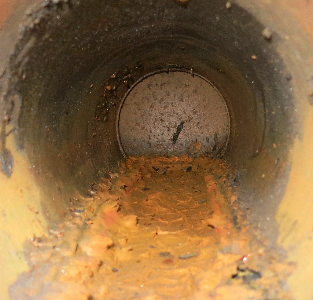
    Alternate title: I looked inside a corroded air tank and now I kind of wish I hadn’t.

    During the disassembly of our thermoforming machine, we noted with worry that the compressor doesn’t have an air dryer between it and the tank, and that the tank is installed in such a way that the water drain valve is basically inaccessible. So any water in the compressed-air system (and due to basic physics, there definitely will be some) would have accumulated in the tank over its years of service.

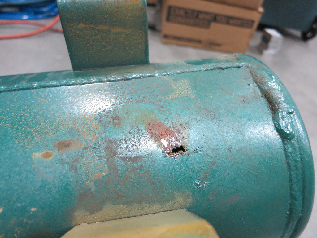
    A short while ago we got far enough in the rebuild to test the compressed air subsystem. Not surprisingly, the compressed air tank leaked and could not hold pressure. Upon closer inspection the leak appears to be rust perforation implying the inside is pretty rusty. So we replaced the tank instead of trying to patch it.

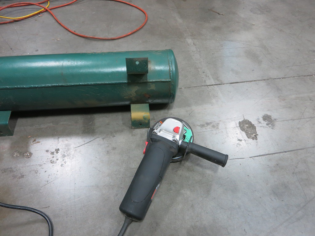
    But I was curious: OK, it’s rusty. But how rusty? During a lull in projects (waiting for some parts to arrive) I pulled out the angle grinder, attached the cutting wheel, and merrily started making sparks.

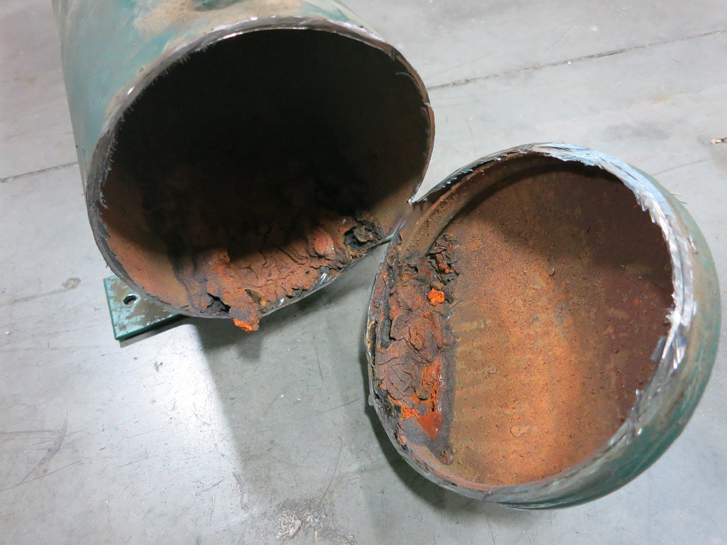
    As I made progress cutting, I noticed chunks of degraded metal were falling out of the gap I had cut. Not flakes of rust – chunks of varying color and texture. This is my first hint things are about to get ugly. Once I cut enough to pull away the end of the tank, we can see inside.

    That’s far more corrosion than I had expected. And while most of the inside surface qualifies as “rusty” the bottom part deserves a stronger word. I can think of a few, but the only one I am willing to put in print is “Yuck”.

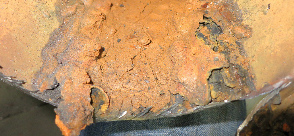
    This sight is something I might expect to see in a home plumbing project fixing the sewer pipe. And this stuff has the soft squishy consistency of… well, the kind buildup you’d find in a sewer drain. This is not something I expected to see inside a piece of industrial equipment.

    This layer has built up across the entire bottom part of the air tank.

    I had originally thought it’d be neat to find the other side of the perforated hole but I was not in the mood to dig through this muck. Even while wearing gloves.

    So let this be a lesson to everybody: If you have a compressed air tank, be sure to drain the water out of it regularly, or this might happen to you!

    (Cross-posted to NewScrewdriver.com)

  • Low Amperage Systems Test

    Roger10/28/2017 at 19:33 0 comments

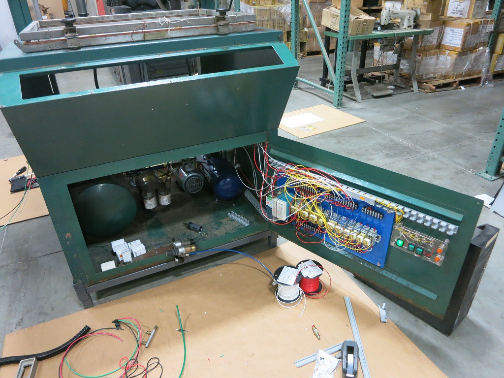
    We got far enough wiring (and re-wiring) the thermoforming machine to perform an integration test of the low-amperage parts of the machine. This covers almost everything except the heating element.

    On the previous test of the compressed air subsystem, we found a leak in the air tank. The leaky tank has since been replaced and this will be a test to see if it works with everything else.

    The vacuum subsystem had also been partially tested earlier. For the previous test we only got as far as the vacuum table solenoid. This time we also have the vacuum lines between the solenoid and the vacuum table.

    The relay panel had been tested with the following configuration:

    • 24V bench power supply as the input.
    • Manually connecting the control wires in turn like an old style telephone switchboard.
    • Multi-meter reading the output.

    This time, the test will put the relay panel in a more realistic configuration:

    • Power will come from the 240V AC to 24V DC power supply on the DIN rail.
    • The control signals will come from the manual operation toggle switch panel.
    • And the most exciting part: the outputs are going to the actual air and vacuum components!

    There was much anticipation and trepidation when the power switch was thrown the first time and we see LED indicators on the power supply indicating the system was live. Every switch thrown was a “Will it work?” mystery. The test did its job, exposing a few wiring errors. Fortunately none of them were damaging mistakes and all were trivial to fix.

    At the end of the evening, we could control everything except the heating element using the manual operation switch panel: Move all the air cylinders, open and close all the air valves, and activate the electromagnets that hold the frame closed.

    We still have lots of things on the to-do list, including some air leaks to track down and fix and plenty of wiring tasks. And there’s still the big intimidating heating element looming in the near future. But all in all, a wonderful morale boosting step on the journey to completion.

    (Cross-posted from NewScrewdriver.com)

  • The Ever-Growing Wiring Job

    Roger10/27/2017 at 20:42 0 comments

    When we started on this thermoforming machine rebuild project, one of the first things we did was to open the control panel. We looked at the nest of wires back there and tossed the whole tangled mess. Those control wires were a basket case we’re happy to leave behind. But the rest of the machine – the power cables and such – looked OK at first glance.

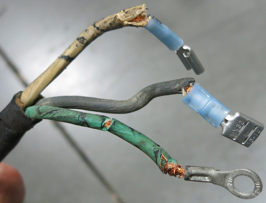
    Unfortunately, they don’t look as good after the second or third glances. Sometimes it’s not a glance at all – it’s seeing (and feeling) them fall apart when we worked in the machine. We expected the wires to be old, and kept our eyes open for signs of aging wires. We just didn’t expect to see them quite so often! This particular example was from the back of the air compressor. When we wanted to clean up the air compressor, we had to disconnect these wires. The act of moving the wires for access and removal broke the age-hardened insulation in many places. So now we have to replace it.

    Every time we get to work on a new area, we find that a new bunch of wires need to be replaced. We’re rapidly approaching the point where it might be easier to rip out every single wire and restart from scratch.

    Wiring is tedious work, part of why good electricians make good money. For us, it’s a very real threat against project completion. We’re interested in having our own thermoforming machine, but that interest tends to drop every time we discover two new wiring tasks for every one completed. It’s a race to complete before everyone loses interest in the project.

    Hopefully the work will be much easier – or at least more rewarding – once the wiring is complete.

    Assuming, or course, we get there…

    (Cross-posted from NewScrewdriver.com)

  • Vacuum Table Frame Removal

    Roger10/26/2017 at 20:04 0 comments

    Around the periphery of the vacuum table on the thermoforming machine, the previous owners built a perimeter using L-brackets. The presence of the frame made sense to help seal in the vacuum. The mystery is the height: The vacuum table and its surrounding frame are the same height as the combined height of the top and bottom parts of the frame holding the workpiece. We had expected the vacuum table to be aligned with the bottom part of the frame, since that's the height the workpiece will be held at. A frame this high would have impacted the workpiece on the way down. We're left scratching our heads figuring out why this is desirable.

    But that mystery isn't important right now. Since we intend to put this machine to work on low-volume hobbyist projects, we will want to change the size of the workpiece frequently. This would be difficult with the existing system, since changing the size of the workpiece means changing the surrounding frame, greatly increasing the up-front setup work. It might be fine for a commercial production machine but such a barrier on a hobbyist machine would probably mean we'd be too lazy to actually use it.

    We're bouncing around a few ideas that should make it easier to change the size of the work piece in the machine. All of those ideas are incompatible with this existing taller-than-expected frame, so it needs to be removed.

    A few jabs with a metal putty knife got things going and the frame popped off shortly afterwards.

    Then the tedious part starts: the putty knives went to work scraping off the sealant that was liberally applied to the bottom of the frame.

    Part of the motivation to invent a new vacuum sealing system is visible here: this surface is quite scratched up and rusty. To make it seal properly with the old system, we need to remove all the paint, sand things flat, and put on a new smooth coat of paint. Unless we can avoid that work with a clever new sealing system.

    (Cross-posted from NewScrewdriver.com)

  • Vacuum Subsystem Test

    Roger10/13/2017 at 19:37 0 comments

    Since we just tested the air subsystem and found problems that will probably require buying parts from McMaster-Carr, we decided to perform a vacuum subsystem test with what we already have on hand to see if we need to add anything else to the shopping list. Only some of the fittings and vacuum lines have been replaced, and the vacuum table itself is in pieces, but we can put together enough to test the vacuum pump, the accumulator tank, the solenoid-actuated vacuum valve, and the fittings and lines connecting them.

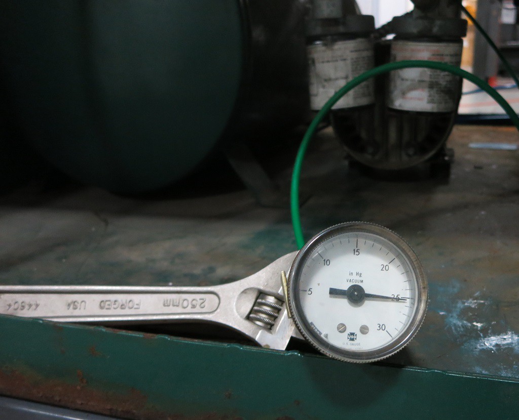
    We were happy to see the system could generate vacuum beyond an indicated 25 inches of mercury. This measurement is taken with a grain of salt coming from the old vacuum gauge that was on the machine. But while the absolute value ("25 inches") might be suspect, the relative value is still useful information. We shut off the vacuum pump and went to work on other things. After 15 minutes, the vacuum held steady enough that there was no visible movement of the needle.

    The next test is the rate at which vacuum is generated. We don't need it to be super fast, but we don't want it to be the limiting factor in cycle time. As soon as the softened workpiece is pulled against the mold, the vacuum should start building back up. It can continue doing so as the completed workpiece is removed and the next workpiece is loaded and heated. By the time the next piece is heated, we want to have sufficient vacuum in the system ready to go instead of having to wait.

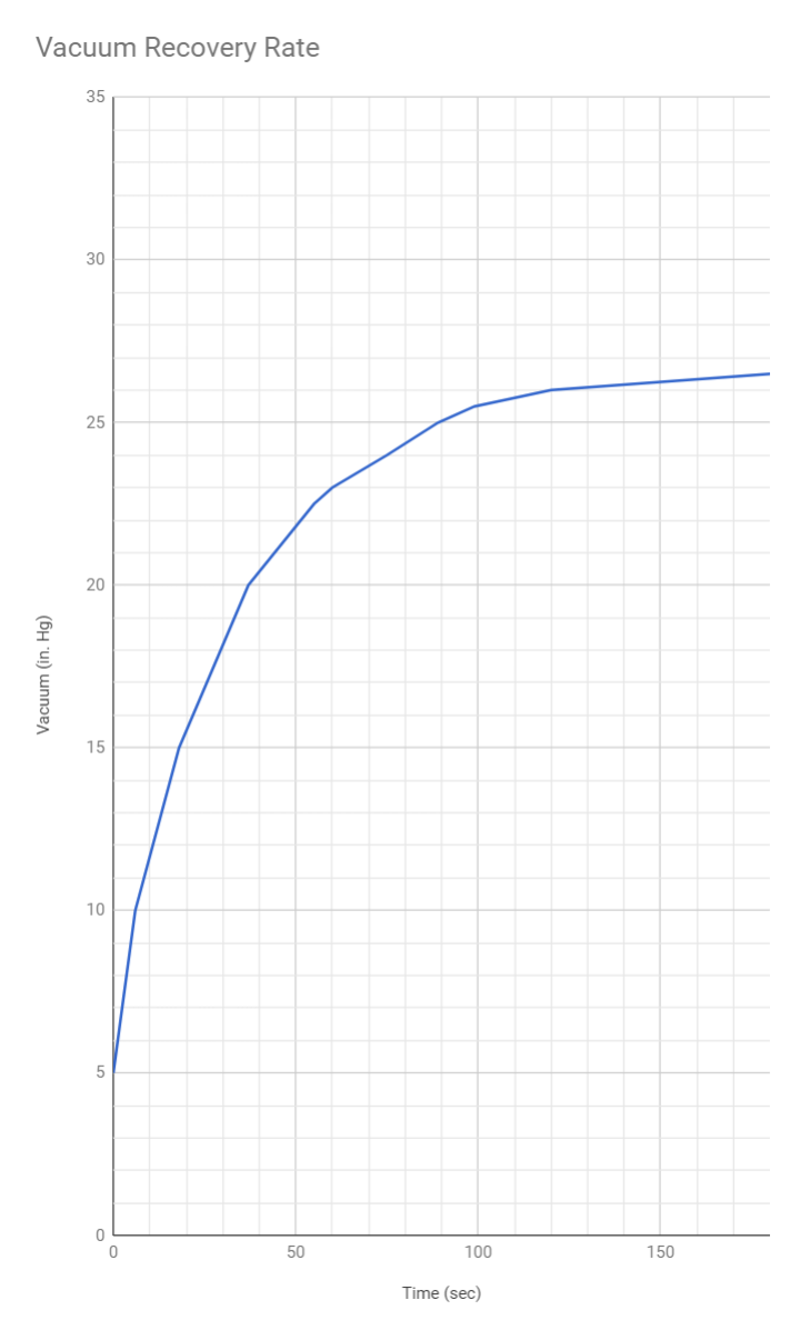
    Using the solenoid, we opened the valve and admit air into the system, dropping the vacuum down to an indicated 5" Hg. We closed the valve and started writing down the vacuum reading relative to a stopwatch.

    The recovery rate is acceptable. After one minute it was back up to an indicated 23" and 90 seconds brings us to 25". It didn't have much grunt beyond that - it took double the time (an additional 90 seconds or 3 minutes total) to reach 26.5", where the needle stopped moving.

    We expect a new pump to recover vacuum more quickly, and provide a stronger vacuum, than this tired old thing. But this performance indicates the vacuum pump will not be the limiting factor in our cycle time and that's good enough.

  • New Compressed Air Fittings and Lines

    Roger10/12/2017 at 20:38 0 comments

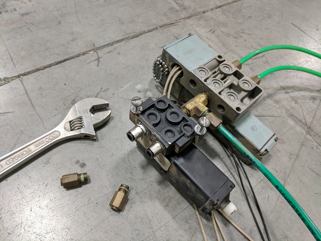
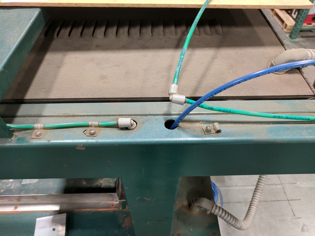
    We've just completed the milestone of replacing the compressed air fittings and lines in the machine. We replaced the fittings because we expect the old air seals within them to have decayed with age. Since we have everything disassembled, replacing them now is relatively easy and reduces many potential points of failure. 

    The same logic also applied to replacing lines carrying compressed air throughout the machine. For extra bonus, the new air lines are blue and the old ones are green, making it instantly visible which pieces have been replaced.

    Once the compressed air subsystem was buttoned up, we wanted to do a subsystem test. Since we have yet to wire up the 220V power distribution, we can't run the built-in air compressor just yet. So we unplugged the output port of the air compressor and plugged that into the shop air.

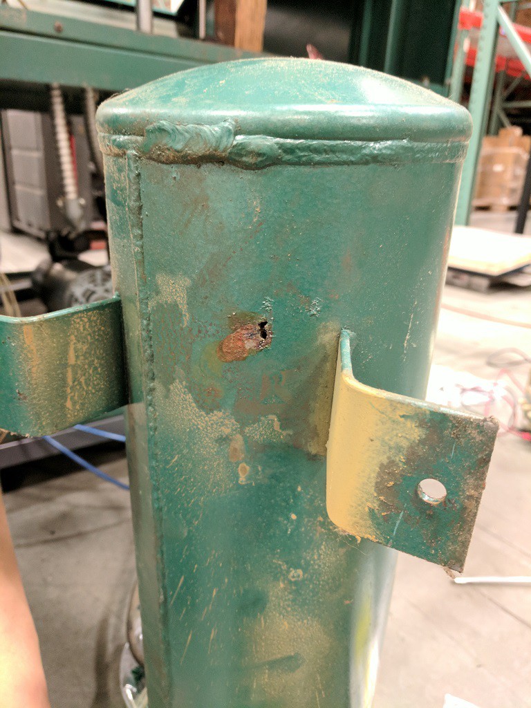
    Loud hissing announced the presence of a leak in the system. We felt all around the newly installed air lines and fittings, but the source of the leak wasn't any of the new stuff. We eventually located the source of the leak to the compressed air tank that we had not yet touched. Before this test, the quality of the air tank was a question mark. Now that we have finally pulled it out and gave it a good look, we have answer to that question!

    During disassembly we noted there was no air dryer between the compressor and the tank, so moisture would have collected in this tank. There is a fluid drain port (not visible in this picture) but it doesn't look like it has ever been used. This hole implies the inside of the tank is a rusty mess and a hole patch repair would only be a futile short-term solution. If we want a self-contained machine not dependent on shop air we will need to replace this tank.

    After this discovery, we disconnected the air line from the output port of this tank and hooked that up to shop air. It allowed us to test the rest of the machine.

    • The mechanism to move the heater rearward seems OK.
    • The mechanism to move the heater forward has a leak that needs to be investigated.
    • Trying to move the heater forward/back repeatedly showed no problems (aside from the above leak.)
    • The mechanism to move the frame up/down each seems OK individually.
    • Trying to actuate up/down movement rapidly would cause the two sides of the air cylinder to fight each other. We are missing an air relief mechanism somewhere in the system. Either we forgot we removed something during disassembly, or an existing relief mechanism has plugged up.

    (Cross-posted to personal projects blog)

  • Old Control Panel Disassembly

    Roger10/07/2017 at 19:35 0 comments

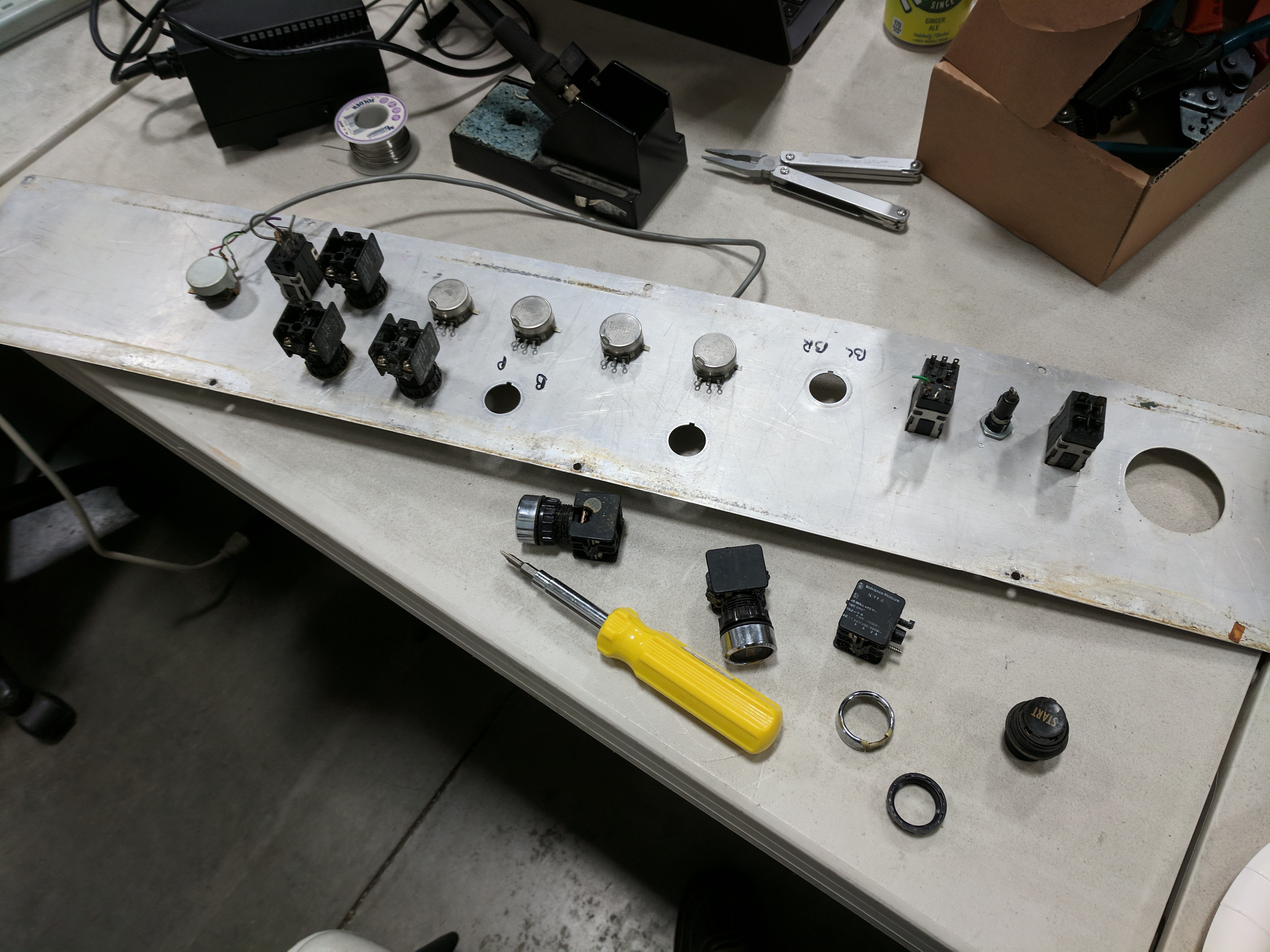
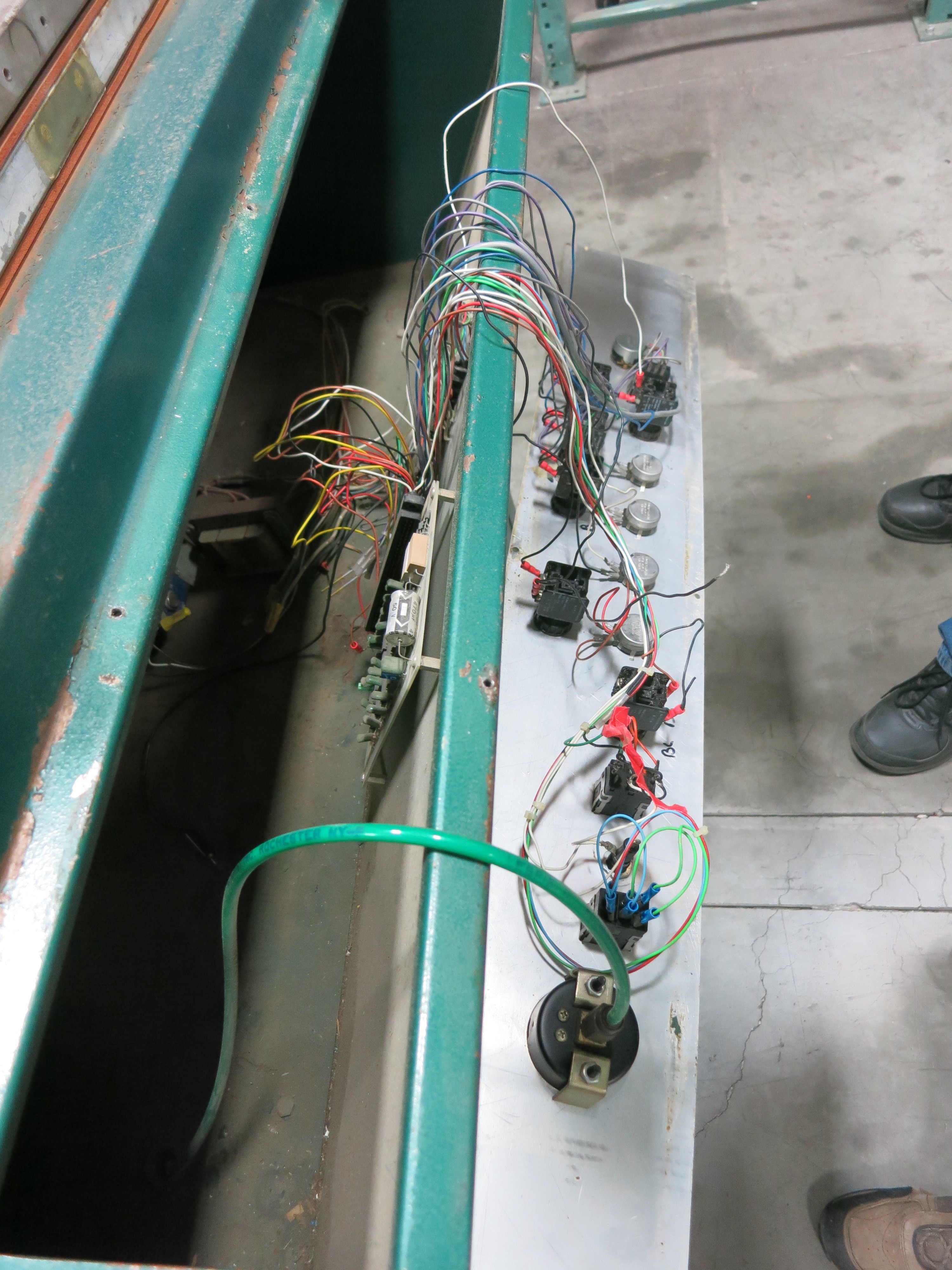
    The old automation panel for the machine was pretty beat up from its decades of service, and the wiring behind it is a mess showing signs of at least three different eras of modification: Two different types of wiring connectors crimps, and some connections were directly soldered. Some wires that were not connected on one end, and a wire tangled in everything that was not connected on either end!

    The wire themselves weren't in great shape, either. The insulation was stiff and rough to the touch, consistent with age. In contrast the switchgear themselves look OK. They are beefy industrial units designed to last practically forever. They might have seen thousands of cycles of use, but they probably still have thousands more of useful life.

    The big rat's nest of wires were cut off and pitched, and the control disassembly began.


    The buttons, switches, and knobs were encased in a lot of cruft, but once we got past that, everything came off the panel (mostly) as expected for well-designed industrial components. The complications came from the three switches that received the direct soldering treatment. It was a challenge to put enough heat into the joint so the solder can melt and the wires removed, but not so much heat that the plastic housing melted and the connector came free along with the wire. One switch was salvaged, one is a question mark, and one was ruined.

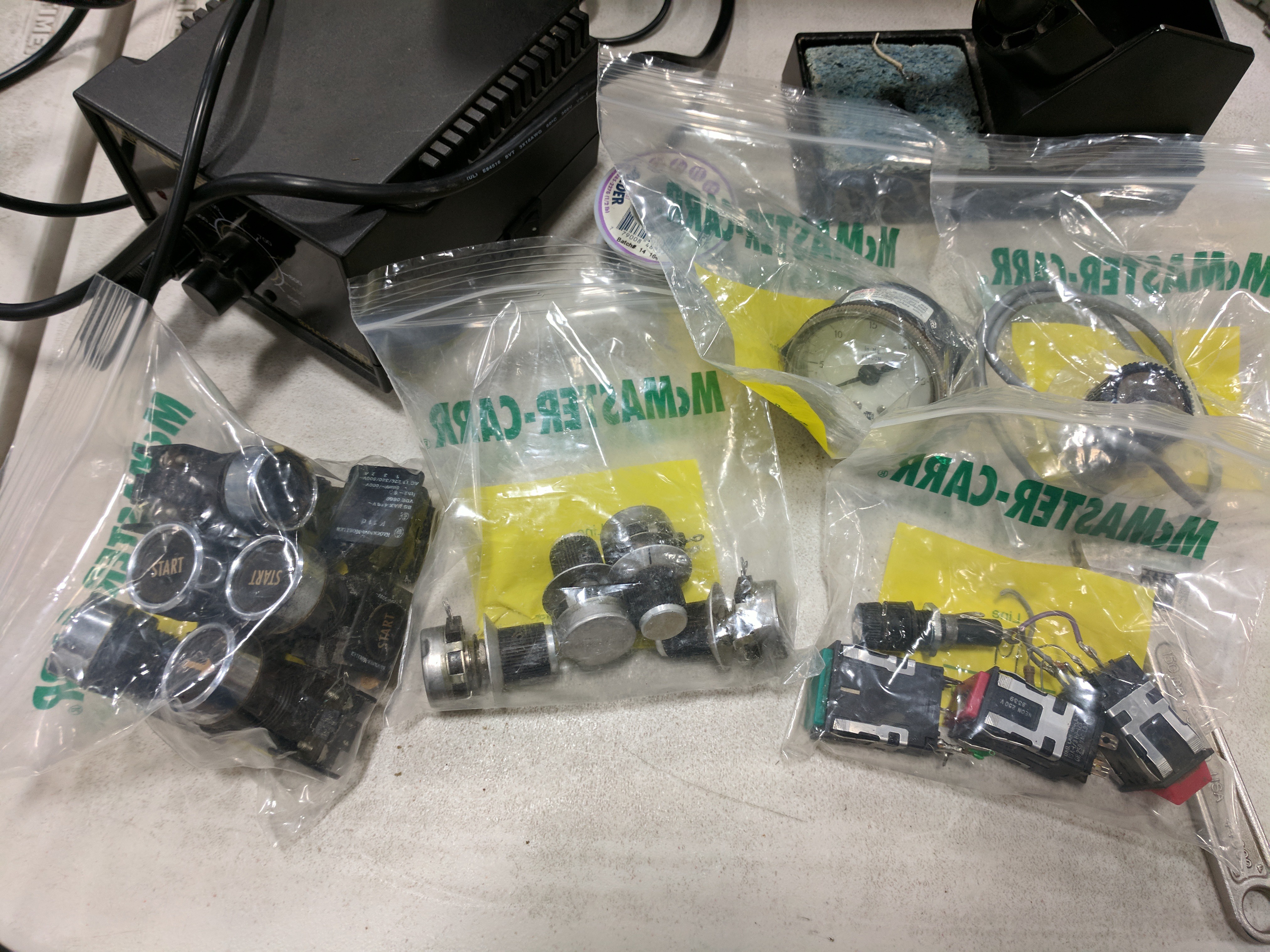
    At the end of the disassembly session, all the salvaged switchgear were placed in used McMaster-Carr ziploc bags. (Any hardware tinkerer has a big stash of those!) They may yet find use in this rebuild project, or in a future project.

  • Session #3: 24V Relays, Machine Work Cycle

    Roger10/01/2017 at 19:36 0 comments

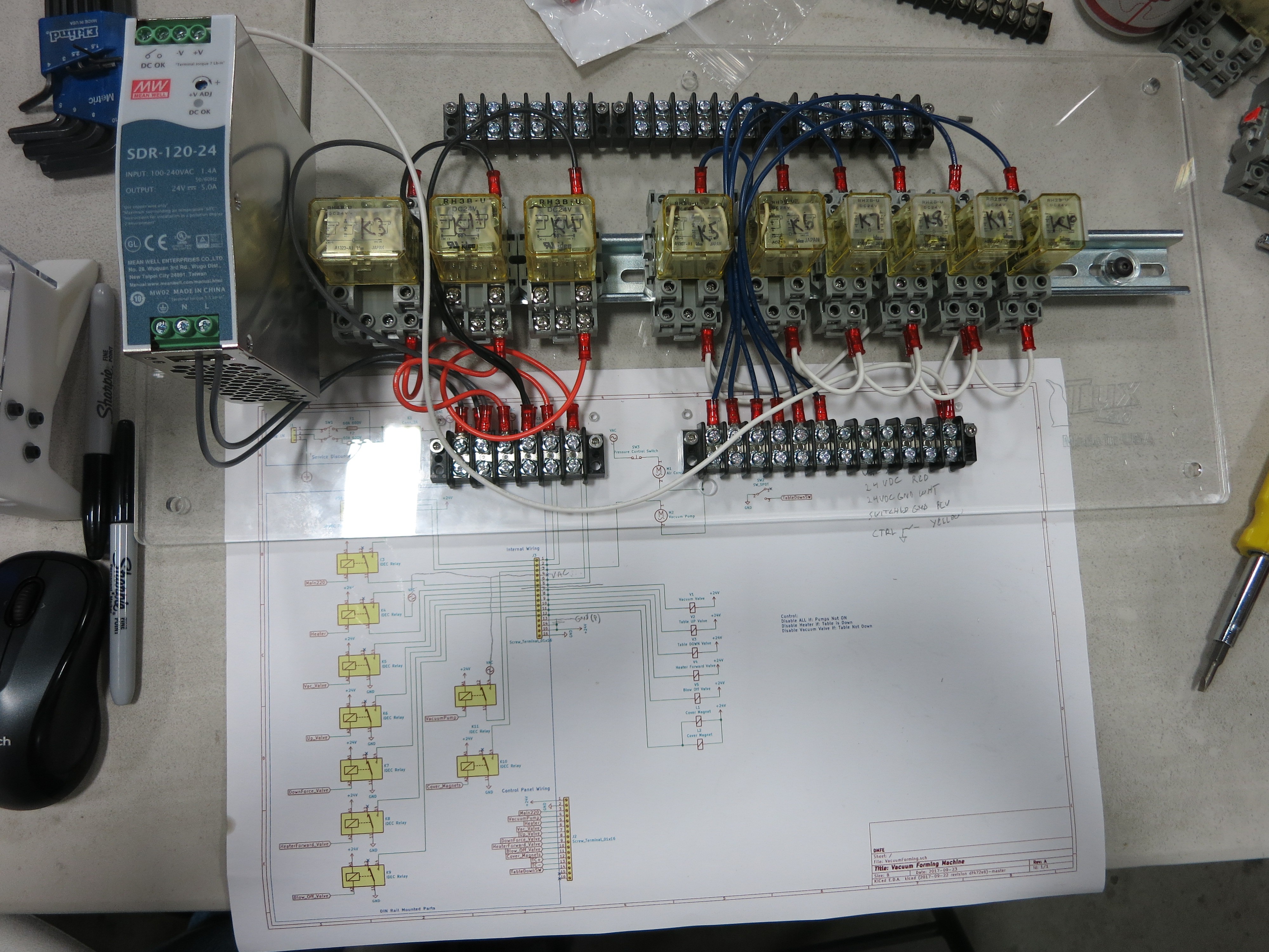
    The main focus of this session was to build the 24V subsystem. The electronics of the machine were powered by an old power supply that took the incoming 240V AC power and reduced it to 24V DC. We're replacing that with a modern switched-mode power supply, and a bank of nine relays will control the machine components. We only needed a single pole relay for each component, but when surplus multi-pole relays were available cheap on eBay, we got those and left connectors unused. The power supply and relays were all mounted to a single DIN rail.


    The nine relays have been assigned to the following functions:

    1. Main: Controls 220V power to the remainder of the machine. The air compressor will have power whenever Main220 is on, we rely on its own pressure control circuit to turn the actual motor on/off.
    2. Vacuum Pump: Power to the vacuum pump.
    3. Heater: Contactor which will turn on the 240V, 40A(?) heater element.
    4. Vacuum Valve: Connects table to the vacuum tank, in order to pull work piece against the mold.
    5. Up Valve: Send compressed air to the "up" side of the frame air cylinder, raising the frame.
    6. Down Valve: Opposite of the above, send air to pull the frame down.
    7. Heater Forward: Normally compressed air will hold the heater in the back position. This relay control the valve that switches compressed air to push the heater forward.
    8. Blow-off: When the work piece is complete, compressed air can be sent to the table to help remove the work piece.
    9. Magnets: When active, holds the frame closed.

    The bottom row of terminal blocks will be wired to their corresponding components in the machine.

    The top row of terminal blocks will be wired to allow control of those components. The first iteration will just have a row of toggle switches for manual control. Later iterations will have some kind of micro controller brain, whether it'll be an Arduino or a Raspberry Pi or something else is to be determined.

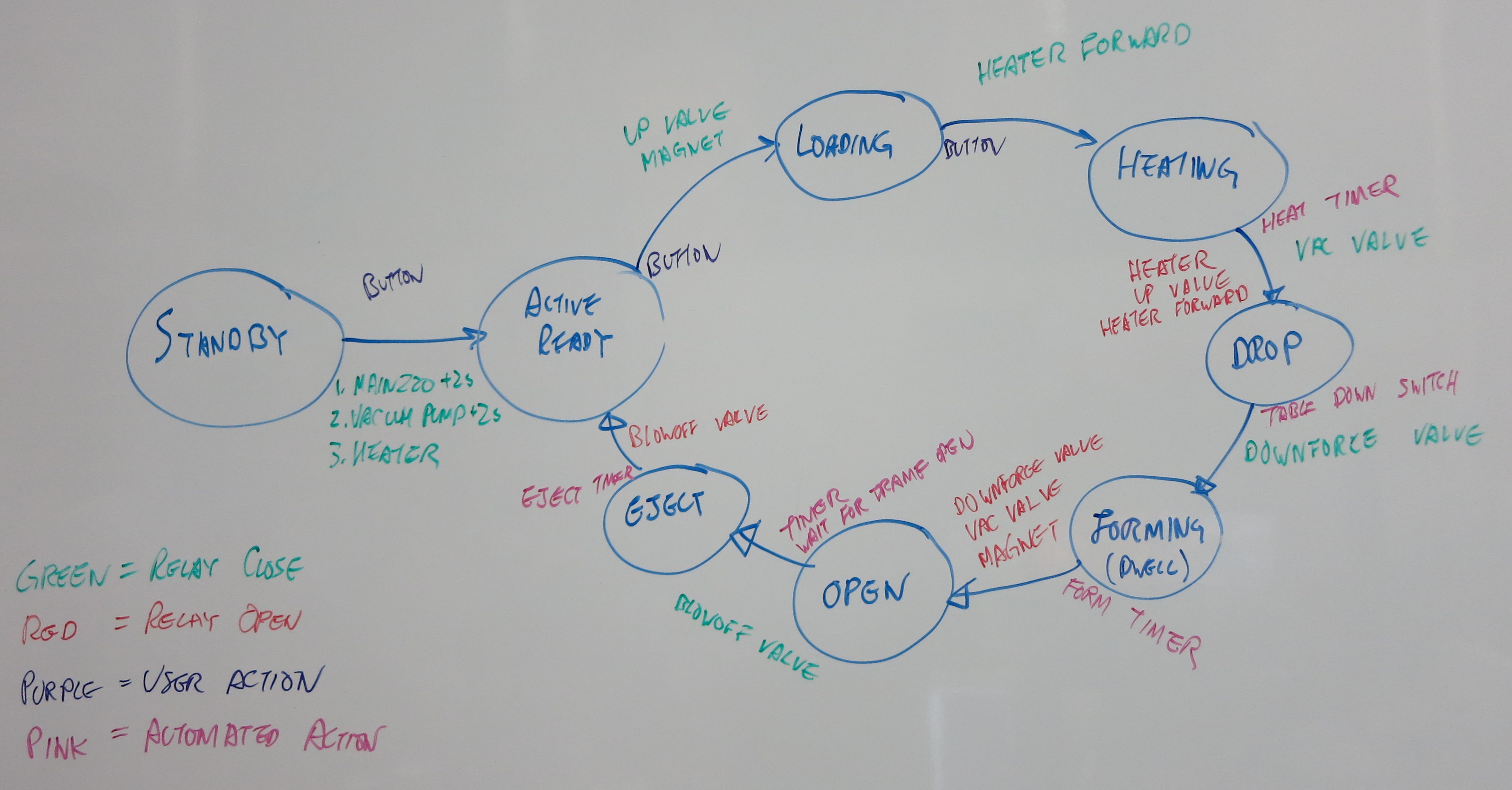
    Which leads to the question... what switches do we flip, and when? We started brainstorming the machine's work cycle on the whiteboard.


    Since this specific machine has never worked in our possession, we can't just write down what it used to do. We pulled up some YouTube videos of similar machines at work, looked at the components in our machine, and made our best guess. We think we have all the major pieces up on the whiteboard but some of the steps are question marks.

    For one example: we were evenly divided on what to do once the vacuum forming is complete. Should we activate the blow-off valve before we open the frame, or after? The state machine has "Open" followed by "Eject", but maybe those two should be reversed. There were arguments in favor of each side and we'll just have to try both to see which works better.

  • Session #2: Air Support

    Roger09/27/2017 at 00:36 0 comments

    The bottom cabinet of the machine held most of the air equipment. There were two motor driven pumps: a vacuum pump and an air compressor. (Or jokingly: one sucks and the other blows.) They each have an attending accumulator tank. 

    It was worrisome to find most of them were hooked up to external connectors. It's possible the machinery were broken or unreliable and compressed air+vacuum had to be fed externally. But it's also possible a previous owner just wanted to reduce noise and vibration and that's why they hooked up the external lines. Or maybe even the reverse direction: the compressed air and vacuum generated by the machine might have been plumbed to be used elsewhere in the shop.

    No way for us to know now, all we can do is test the machines to see how they do!

    A brief test of the vacuum pump managed to pull 26 inches of Mercury, which is good enough as a starting point.

    The air compressor also got a brief test and managed 40 psi, which was not promising. Fortunately, a disassembly and cleaning was enough to restore it to 100 psi level of performance.

    The air and vacuum lines are relatively inexpensive to replace and plans are to do so. The electrically controlled air valves are more expensive and will have to be tested. The two air cylinders got a quick test in the previous session and they (1) move and (2) are not hissing like they have leaks. A great place to start.

    There are two accumulator tanks - one for the compressor and one for vacuum - they are question marks.

  • Session #1: Disassembly

    Roger09/27/2017 at 00:18 0 comments

    The first session was spent taking everything apart. We want the machine down to its fundamental components and rebuild from there. We decided this after seeing the tangle of new and old air lines, vacuum lines, and wires. There's been lots of work done to this machine over its lifetime of service and we don't care to put time into figuring out why somebody did something years ago.


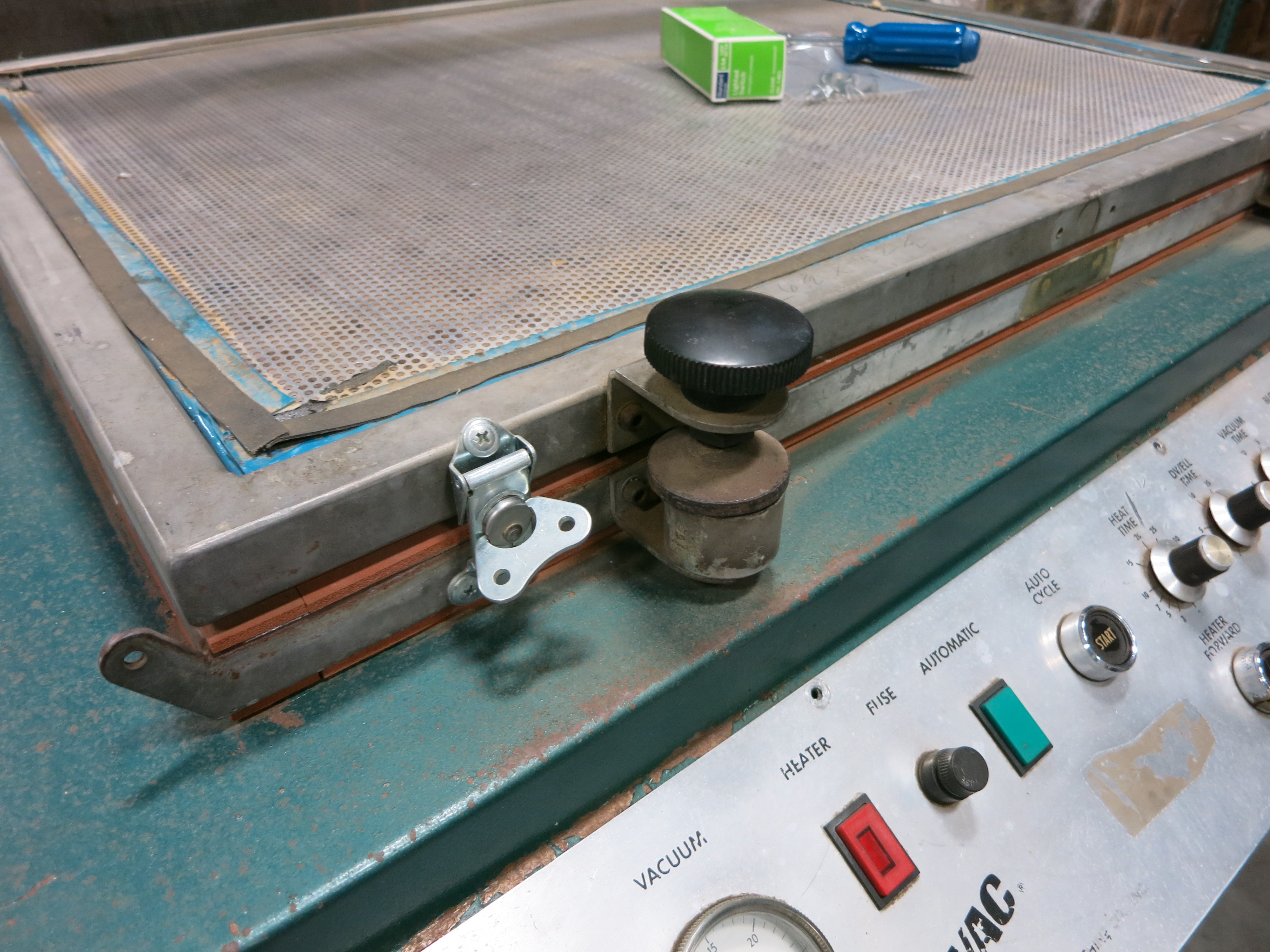
    Here's one of the puzzles: aftermarket Home Depot quality latches. The obvious answer is that somebody had to install them because the adjacent electromagnets no longer work to hold the frame shut. But when we energized the magnet (24V 0.45A) it seemed to hold the frame quite well. Why were the latches installed? We may never know.


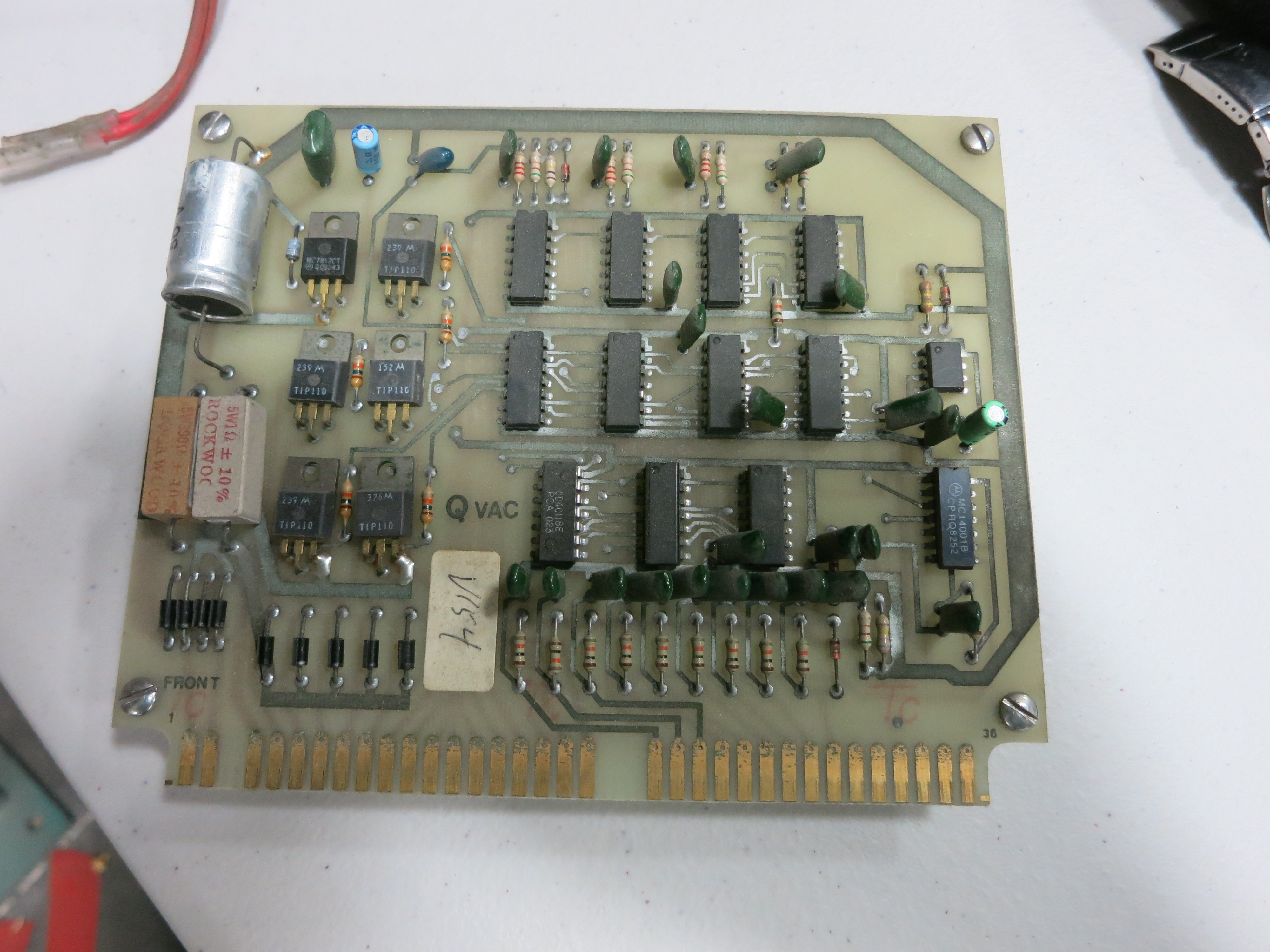
    The advertising copy for the current-generation Q-VAC PC Series machines tout its labor-reduction automation capabilities. Judging by controls, this ancestor is also quite proud of its automation. The rebuild crew here, however, is rather less impressed by the ancient circuitry. Since we're interested in low-volume maker projects, and not high-volume commercial production, automation is not a priority. We want to get the machine up and running in a manually-operated fashion. If and when we need automatic cycle we'll tackle that with a more modern brain to orchestrate the process.


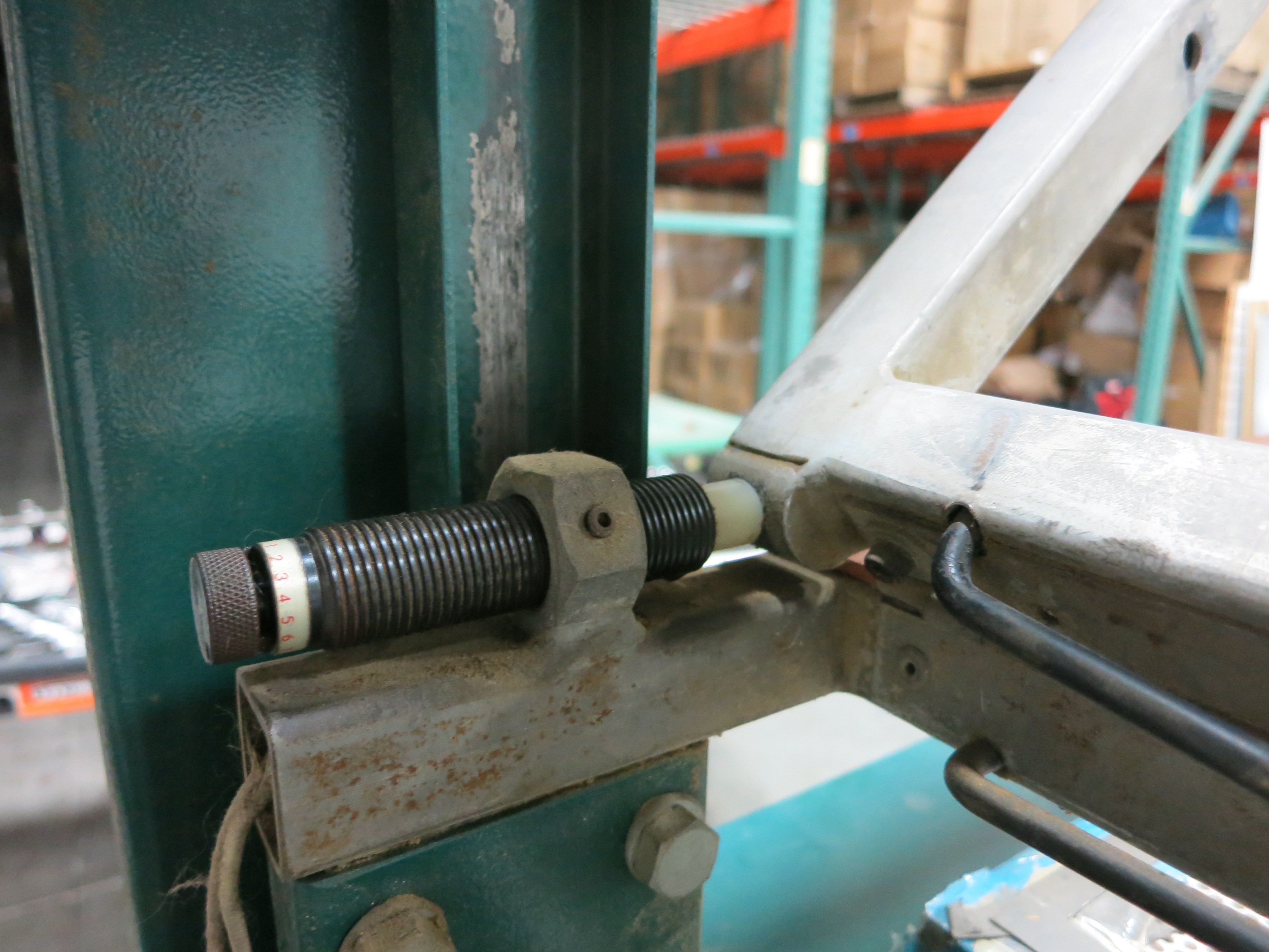
    Given the age of the machine we didn't hold high hopes that replacement parts would be available. Every time we find something it's a pleasant surprise. For example: when the electromagnets release, a torsion spring will pop the frame open. At the top of the travel, these hydraulic dampers keep the frame from slamming open. The dampers have long since worn out and leaked out all of the fluid. We refilled with oil and found one still worked and one did not. And they both started leaking so it wouldn't be long before they both stopped working again.

    The label said "Enidine .5B" and a web search found we can still get new replacements straight from the manufacturer. Or buy surplus from eBay, or a rebuild kit. Awesome.


    The machine was pretty gutted by the end of the disassembly work session.

View all 10 project logs

Enjoy this project?

Share

Discussions

carycii wrote 11/12/2022 at 15:57 point

I just picked up one of these machines used.  It is currently functioning, but one of these days it would be nice to update the electronics.

I would love to see an update on your project.

  Are you sure? yes | no

Similar Projects

Does this project spark your interest?

Become a member to follow this project and never miss any updates