 Bruno Laurencich
Chordata is a motion capture system that you can build yourself. Our goal is taking the world of motion capture to the universe of DIY technologies with an Open Hardware approach.
For a quick introduction you can visit our website.
Detailed technical information, building instructions and user manual are available at our wiki.
If you have any doubts, of just want to share your thoughts on the project, join the discussion at our forum.
Or perhaps you prefer to dive directly into the CODE or KICAD sources at our repositories at gitlab.
🚀 Kickstarter Campaign [120% funded! ⚡️🔥]
The Chordata Motion Kickstarter campaign has raised over €42.000, that's a 120% of our initial funding goal. We’re blown away by the incredible response we received.
Thank you all for the support you've given this system!
Check out the campaign here: http://chordata.com/kickstarter

The project at a Glance:
you can get an idea of what Chordata is all about with the infographic below
Why Chordata was created
The origin of Chordata was a basic need. Bruno, our tech lead, wanted a way to register dance moves for a performance piece, but none of the tools available matched his needs (nor his budget). A lot has happened since then: now the system is publicly available (as a BETA release), and lots of documentation can be found on the sites described above.
Just for the record we leave the original description of the project below, as it was written when the main parts of the system were under development.
Original description of the project:
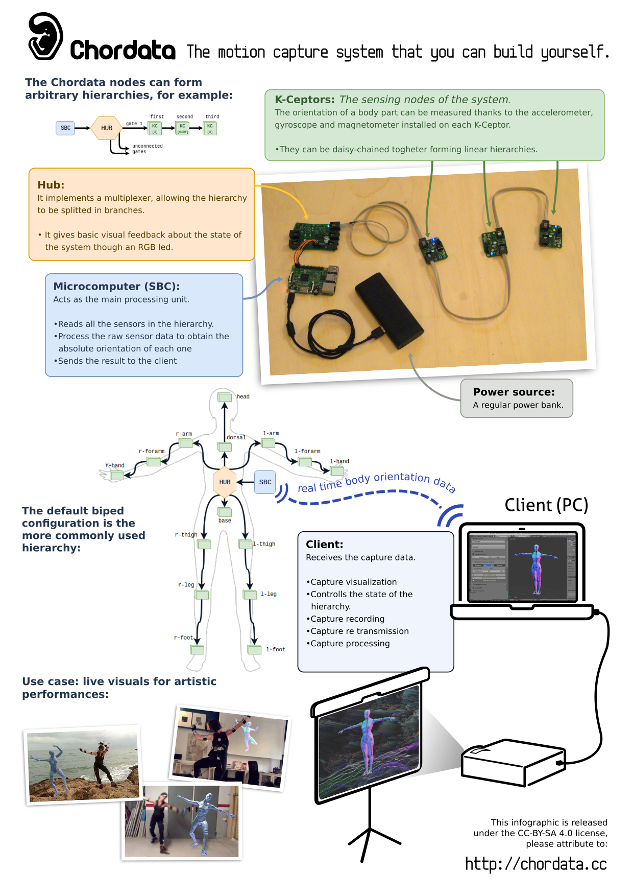
This project consists on three parts:
Hardware (K-Ceptor):
Motion capture is about getting the orientation of every body limb or part at real time as accurate as possible. A simple MEMS IMU device*, and freely available sensor fusion algorithms are enough to get a decent result. The problem starts when you want to get the data of several devices.
Most of this devices came with an i2c interface, but their address is fixed in the hardware. So one of the building blocks of Chordata is the sensing unit capable of coexisting with several “siblings” on the same bus: the “K-Ceptor” It consists of a LSM9DS1 IMU, and a LTC4316 i2c address translator.
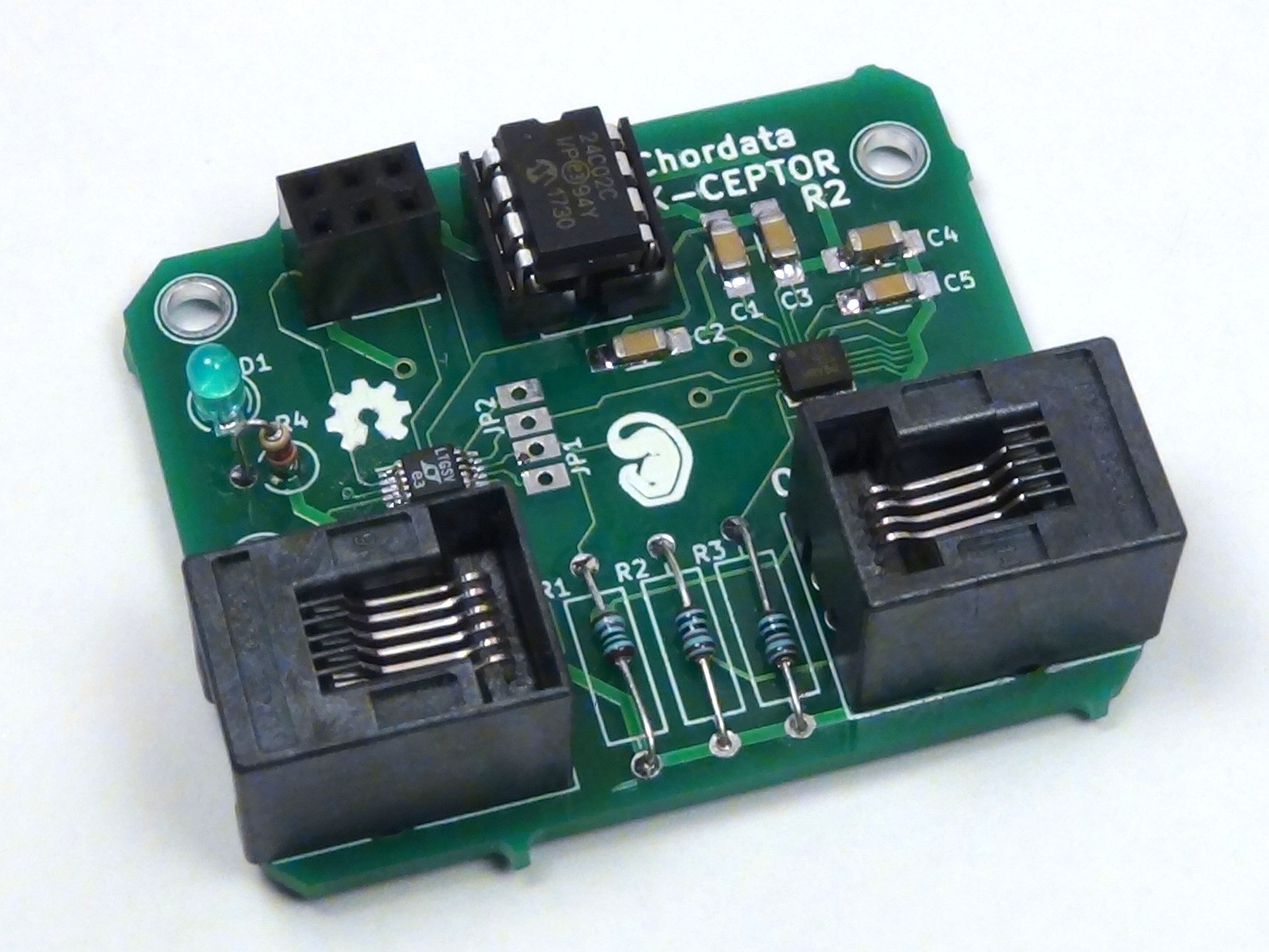
While developing and prototyping we hand-soldered lots of these boards in house, so having the minimum possible number of SMD components per board made that process a little easier.
Software (Notochord):
Getting the data of a lot of sensors on real time, processing it, and send it in an easy-to-read format to some client is not a simple job, so I’m developing a software from scratch to deal with it.
It is responsible for:
- Building a digital model of the physical hierarchy of sensors. Initializing the i2c communication on the Hub, and running the configuration routine on each of the sensors.
- Performing a reading on each of the sensors at the specified refresh rate.
- Correcting each sensor reading with the deviation obtained on a previous calibration process.
- Performing a sensor fusion on the corrected sensor reading, obtaining absolute orientation information in form of a quaternion.
- Sending the orientation data, together with the sensor_id and a timestamp to the client using an open protocol (such as OSC)
After several testing I discovered that using an Single Board Computer running linux was the best choice to host such a program, so all of the development of this part of the software has been done on C++, using a Raspberry Pi 3 as the hub. Some of the advantages of this type of hub, in comparison with simpler microcontrollers are:
- It’s not an expensive component.
- Programming and debugging is enormously simplified.
- Some of them, like the rPi3, came out of the box with all the communication peripherals needed to perform a confortable capture, with the remarkable example of the Wifi adapter.
The choice of performing the sensor fusion inside the hub is based on:
- Mayor cost of the IMU units capable of performing sensor fusion on-chip
- Mayor accuracy of the sensor fusion performed after the raw data is corrected by a previously done calibration.
- Since the bandwidth in the i2c bus generates a bottleneck in the sensor’s data acquisition, the fusion sensor processing inside the hub doesn’t add a significant overhead.
Software (Client):
Since the protocol with which the data is transmitted is clear, the client can be anything that is capable of displaying a 3D skeleton.
Most of the time I'm using a python script running in Blender that grabs the quaternion data from OSC, and rotates the bones of a 3D armature.
The idea would be releasing a basic client in the form of a Blender add-on responsible for:
- Establishing some handshake communication with the hub, checking compatibility and status.
- Communicate the status to the user (the human in front of the computer).
- Act as a GUI to run the on-pose calibration procedures and start the capture.
- Display the preview of the capture on real time, and allow the user to register part of it.
- Allow an user with a basic experience on Blender to create a custom distribution of the sensors on a virtual model of the human body, export it on an structured data format (like xml) and send it to the hub.
*For the sake of simplicity here I refer to IMU device, but to be correct I should say IMU (gyroscope and accelerometer) + magnetometer