 Bruno Laurencich
Here's a video showing the current state of the capture. This 3 sensor prototype it's with what I've been working on in the last months, even if it's not as spectacular as a whole body capturing suit, it allowed me to easy test the features as they were implemented.
The focus on this part of the development was put on:
- General stability of the program.
- Capability for reading sensors arranged on any arbitrary disposition (or hierarchy).
- Obtaining readings of each of the sensors at a regular interval, no matter in which part of the hierarchy it was.
- Capability for reading a single sensor on the hierarchy, process it's raw data and generate calibration information. Dump this information to a file.
- Implementing a correction step for each sensor, with data obtained on a previously done calibration, before the sensor fusion.
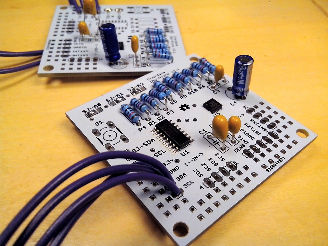
The Imu-Proto sensor unit,
physical base of the prototype is simple pcb featuring a IMU sensor, and an i2c multiplexer. The idea was that this units should be easily interconnected allowing the creation of tree shaped hierarchies. So it had a 4 pin input and output carrying the current, and the i2c bus. It also exposed pins for the secondary gates of the multiplexer.
This arrangement was great for testing, but now I'm working on the creation of more user-friendly version of the sensing unit, which will have the following features:
- -Lack of a multiplexer which will be on a separate unit, and instead implement an address translator.
The multiplexer works fine, but it wasn't really used on all nodes, in the other hand it added unnecessary overhead to the bus, having to switch it for each sensor before the reading. Instead having it on a separate unit will allow a more flexible creation of arbitrary trees.
- An easy pluggable connector.
Of course, having to solder 4 wires in order to create the suit wasn't flexible at all. This connector should allow the performer to freely move while keeping the connection stable, should be cheap and common, and not excessively bulky. At the moment I'll go with the RJ-12 connector (the one regular telephones use).
- An on-board memory.
The main function of this memory will be storing the sensor calibration data. This calibration should only be performed once in a while*, and until now the generated data was stored on a file in the Hub, not allowing a particular sensor to change Hub, or position on the hierarchy.
(*) I'm talking about the sensor calibration, not to be confused with the pose calibration which should be performed before every capture.
Discussions
Become a Hackaday.io Member
Create an account to leave a comment. Already have an account? Log In.