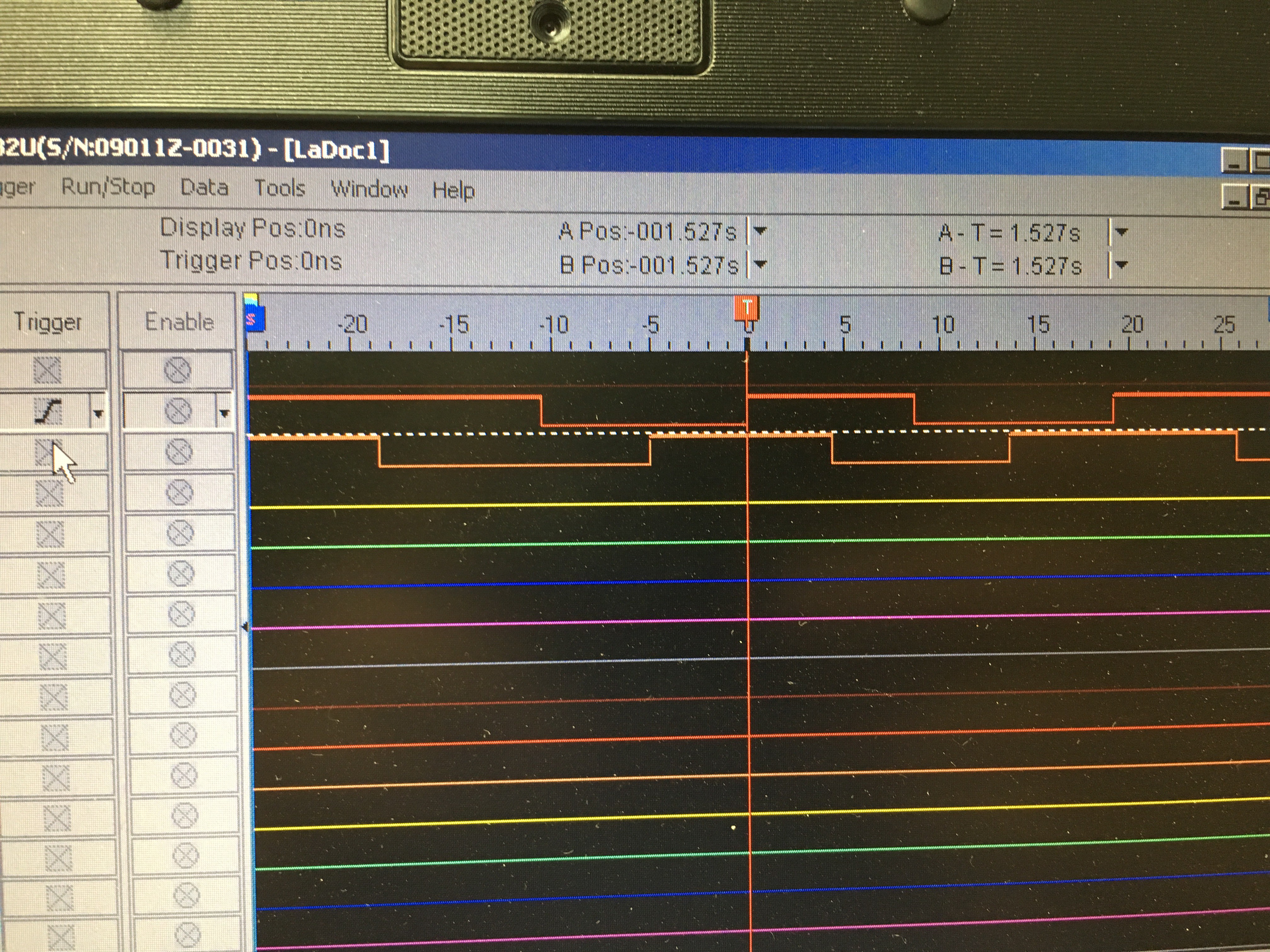
The most common way of detecting pulses & direction is to use quadrature encoding, this is where the pulses are shifted 90*. So how to you create this type pulses with a hall sensor and magnets?
There are a number of types of hall sensors: unipolar, bipolar switch and bipolar latch, and it is the last one that is ideal for creating a quadrature signal. A bipolar latch hall sensor switches on when it detects one magnetic pole (lets say north) and it switches off when it detects the other (south) magnetic pole. So when you create a circle of magnets with alternating north and south poles facing the sensor, the result is a signal with a 50% duty cycle (when the rotation speed is stable).
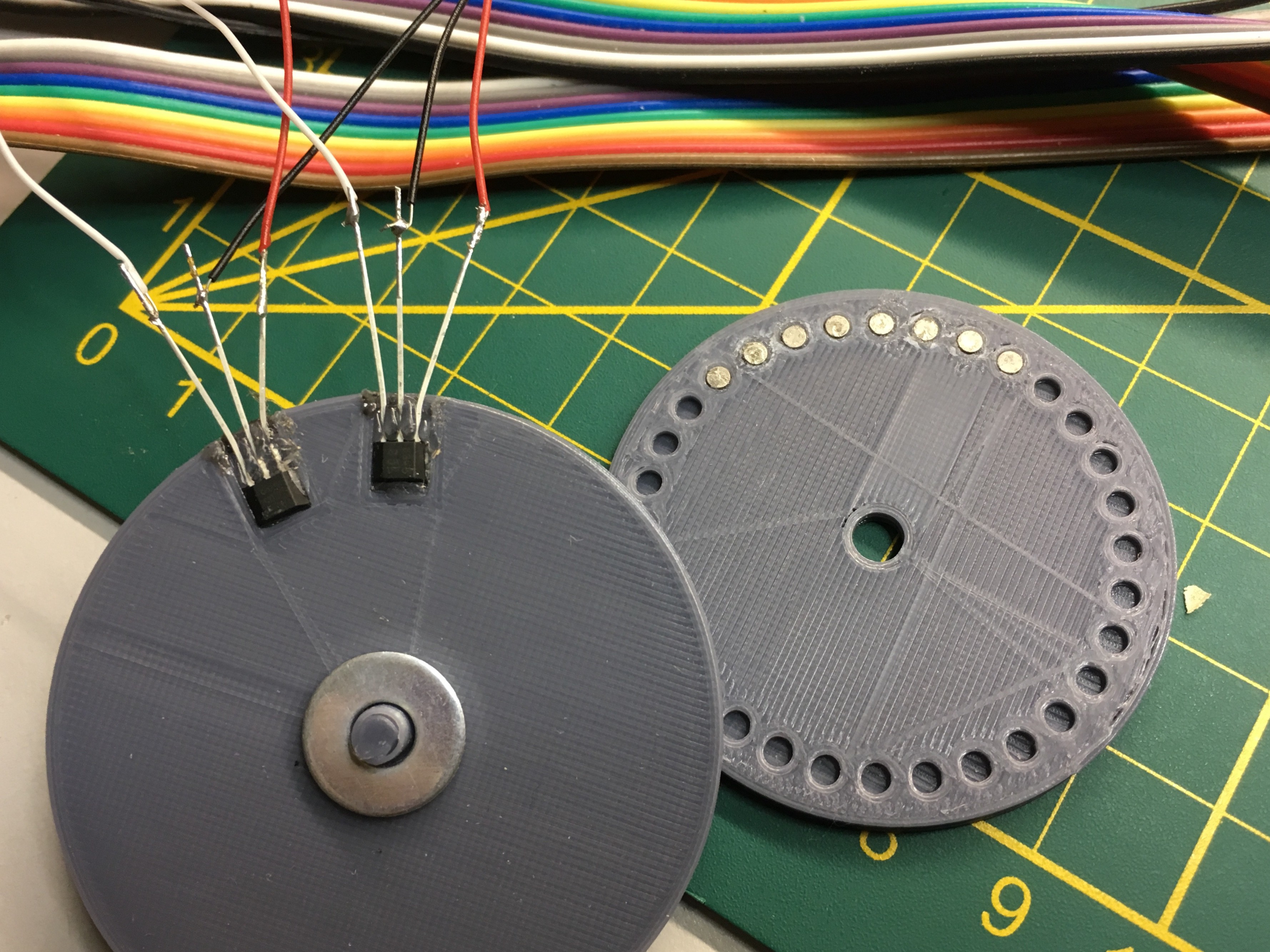
I used my 3d printer to create a small disc with 32 (2 mm) holes and I glued in 8 teeny tiny neodymium magnets. I also printed a base for the disc spin on and to hold the hall sensors in place. The sensors are offset by 28.125 degrees (360 / 32 = 11.25, (2 * 11.25) + (11.25/2)), so that when one sensor is directly underneath a north pole, the other one is halfway between a north and a south poll.

And the resulting signals

 the.wretch
Discussions
Become a Hackaday.io Member
Create an account to leave a comment. Already have an account? Log In.