Close
0%
0%

WiFi AC controller

WiFi-enabled controller for AC units which accept an analogue control signal.

Similar projects worth following
The basic requirement for this project was to develop a solution based around an ESP8266 module which would allow for the AC units (FCUs) at the office to be individually controlled. This to replace the existing and highly inadequate 'solution'.

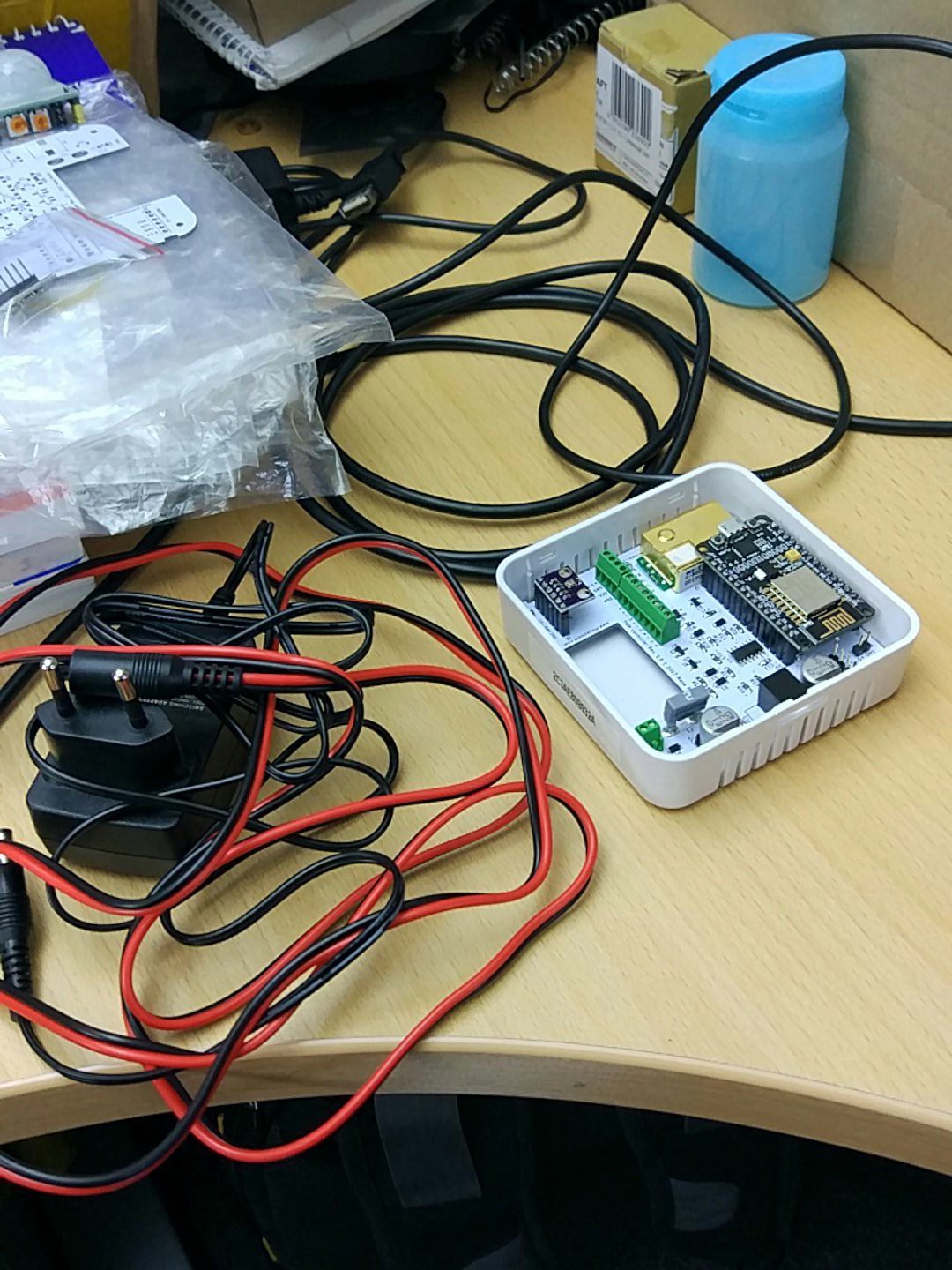
What this new controller offers is room for a NodeMCU board. Four pins of the ESP8266 are used for PWM output, which are each passed through two RC filter stages to smooth it to a DC signal. This signal is then amplified by an LM324D quad opamp.

The board also provides room for an MH-Z19 CO2 sensor, a BME280 temperature sensor breakout board onboard and a further I2C connector to allow for a second, external BME280 sensor.

A 12VDC input is used to power the board. A 5VDC DC-DC converter module down-converts to the input voltage required for the NodeMCU board and the MH-Z19.


A modified v1.0 board has successfully finished testing, with a v1.1 PCB ready for testing.

Basic feature list:

  • 12 VDC powered.
  • Based around NodeMCU module.
  • MH-Z19 CO2 sensor option.
  • Internal BME280 sensor option.
  • External BME280 sensor option.
  • Internal HC-SR501 motion sensor option.
  • Four 0 - 10 VDC output channels for AC units.
  • Breakouts for other GPIO pins.
  • Shaped to fit into CamdenBoss CBRS01VWH sensor enclosure (wall/ceiling mount).
  • Dimensions (roughly) 80x80 cm.

The NodeMCU (ESP8266) is an integral part of the board. It handles the WiFi (obviously), and reads out the CO2 and temperature sensors. It also controls the PWM output which drive the four output channels for the AC units.

For our purposes, the ESP8266's firmware uses an MQTT-based solution (based around the Sming framework), which communicates over a TLS-secured connection with a backend which provides the actual intelligence. An active loop is maintained to ensure that each controller unit is performing as intended.

The temperature readings are integrated into the backend logic which controls the AC units, to allow for the optimal temperature to be maintained by careful manipulation of the 1 - 4 AC units connected to a single controller.

There is also an option to add a motion sensor (HC-SR501) to this setup, using the +5 VDC and GPIO pins on the PCB, slotting the motion sensor board into the cut-out in the PCB after cutting an appropriate hole in the enclosure.

latching_2state_switch_v01_gerber.zip

Gerbers for the v0.1 version of the 2-state latching switch.

Zip Archive - 32.57 kB - 12/22/2017 at 22:30

Download

latching_2state_switch_v01_-_bom.html

BOM for the v0.1 version of the 2-state latching switch.

HyperText Markup Language (HTML) - 2.32 kB - 12/22/2017 at 22:29

Download

i2c_relay_controller_-_bom_v0.1.html

BOM for the i2c relay controller board.

HyperText Markup Language (HTML) - 1.77 kB - 12/22/2017 at 19:47

Download

i2c_relay_controller_v1_gerber.zip

Gerber files for the i2c relay controller board.

Zip Archive - 27.21 kB - 12/22/2017 at 18:26

Download

bom.html

BOM for the v1.1 version of the PCB.

HyperText Markup Language (HTML) - 3.66 kB - 12/21/2017 at 20:36

Download

View all 6 files

  • 2-State Latching, WiFi-enabled switch added

    Maya Posch12/22/2017 at 22:32 0 comments


    I have added the Gerbers and BOM for the above board. It's an improvement on the current perfboard-and-NodeMCU bodge that is used in the mini-BMaC installation at the office, fitting neatly inside a standard electrical box. All it needs now is a fancy enclosure. Ideas are welcome there :)

  • Introducing the BMaC project

    Maya Posch12/22/2017 at 19:26 1 comment

    Since embarking on the 'WiFi AC controller' project quite a few months ago now, I have learned more than I ever wanted to know about building (climate) control, and seen the scope of what had seemed like a simple project at first balloon in size as a result.

    Instead of just controlling the fans in what I later learned are called Fan Coil Units (FCUs), the need also arose to control the valve(s) for each FCU, and naturally the backend service should be able to read out and switch the system state for a segment from heating to cooling and back.

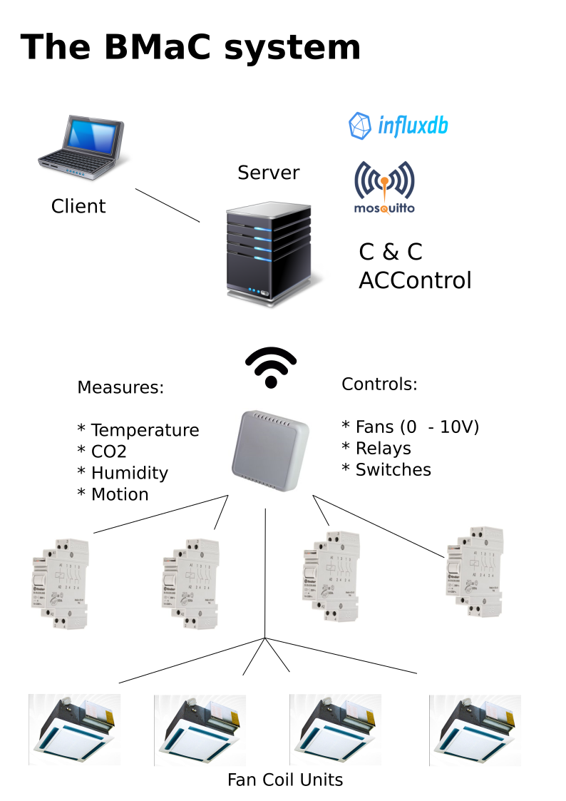
    As a result I ended up with what I now lovingly call the Building Management and Control (BMaC) project, which in graphical format looks somewhat like this:

    Slightly more complex than just having a microcontroller or similar driving a fan, I guess.

    As illustrated in the above graphic, the idea is that one node (CMN) can control up to four FCUs and the relays that control the valves while also providing real-time sensor data on temperature, humidity, air pressure and CO2 levels. Since these sensors placed in the midst of the area that is being climate-controlled, the backend service (ACControl) can make rapid and accurate changes to fan and valve settings due to very short thermal feedback loop.

    Because I was running out of GPIO pins on the ESP8266 after adding the i2c and PWM (and motion) functionality, I decided to create an i2c-based GPIO expander device. This took the form of an MCP23008-based design, along with an ULN2003 and some loose components for flavour. Today I added a PCB design for it to the project page.

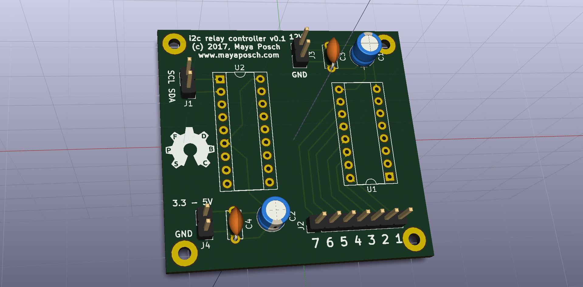
    This i2c relay controller board looks like this:

    It's a positively tiny (48x46 mm) board despite being based on a socketed PDIP design and using only through-hole parts. Since it's supposed to drive 12 VDC relays, I figured that a bit of added robustness and ease of replacement (blown ULN2003 chips or such) would be a bonus.

    A perfboard-based version of this design currently runs inside the small BMaC system here at the office, driving three relays which in turn control the 24 VAC thermoelectric actuators on the respective valves.

    The final part of the BMaC system is the latching relay switch, for which I will release the design as well. This component is only needed in 2-pipe FCU systems, however.

    The software for everything can always be found on the GitHub page linked from the HaD.io project page.

    As mentioned in a previous log already, I recently got laid off, so that I won't have the opportunity to further develop the small BMaC system at this office. I am however definitely still interested in developing this system further, either as a hobby project or as part of my next job.

  • First release

    Maya Posch12/21/2017 at 20:57 0 comments

    Today was a big day for the project, as I finally uploaded the Gerber files for the v1.1 revision of the PCB, along with the BOM. See the respective sections on the project page for these files.

    Software for the ESP8266 board itself, along with the Command & Control and AC control services, etc. can be found on the GitHub page, helpfully found on the project overview on the left side of the page.

    While the revision 1.0 of the PCB is working all right, it nevertheless required a few hardware botches, mainly the bridging of the diodes before the emitter-follower transistors, and the omission of the pull-up resistors. Even with this bodge, the control voltage on the outputs can only do 0 to about 9 VDC, instead of the full 0 - 10V range. Not a major issue, but still.

    In short, the v1.1 revision changes the following:

    • Enable 0 - 10VDC output range for fan control.
    • Replace the clunky MiniBlade fuse with an SMD polyfuse.
    • Optimise routing.
    • Fix footprint for DC-DC module.
    • Fix drill hole size for MH-Z19 footprint.

    As of this point the v1.1 revision has not been produced as physical PCBs yet, though as they are based on the functioning first revision, it should just Work Fine (tm).

    The Gerbers themselves are released as open source hardware (OSHW). The KiCad project files will be added to my GitHub account once I have sorted out which files are actually required in the project folder :)

    For the full functionality with FCU airconditioning one still needs the relay controllers. I will release the hardware design for this tomorrow, along with the remote switch design files. Documentation for the whole Building Management and Control (BMaC) system as I have come to call the contraption is still pretty minimal, but will be extended over the coming time, along with the functionality of the AC control service and related components.

    Feel free to peruse the project, maybe try it out and give me some feedback :)

  • It's alive

    Maya Posch12/20/2017 at 18:10 0 comments

    So after some last minute tweaking and fiddling, the project seems to be working as designed. Lots of details to tweak on when and how fans and valves are controlled and maybe it shouldn't keep the same constant temperature overnight and during the weekends, but as a proof-of-concept it seems fine.

    Switching the entire section from heating to cooling and vice versa using the wireless switch module works as intended, and as one can see in the above image (both Großraum 3 graphs), a constant temperature is being maintained in this section of the office (open office plan) with just 3 out of the 13 FCUs under its control.

    Also in the image are the two sensors on my desk (obviously), and a sensor in a meeting room (MemoryLeak). It's interesting to compare my own creation with the old system as installed in a properly sized room. Seems fairly similar, but perhaps less aggressive due to the smaller thermal feedback loop for my system.

    Today I started releasing the software for the project (https://github.com/MayaPosch/BMaC), with the hardware designs (KiCad projects) to follow soon.

  • Quick update

    Maya Posch12/01/2017 at 19:49 0 comments

    Some of those who have been following this project may have noticed that there haven't been updates for a while. There are two reasons for this.

    The first reason being that this was a project that was being worked on during 'spare' time at the office and hence mostly shifted into my own spare time. The second reason involves me getting laid off due to changes in the focus of the company, making a primarily low-level, system developer - like yours truly - redundant.

    At this point the three AC units (technically Fan Coil Units, or FCUs) have been hooked up to the system for a while, with a simple control service (written in C++ & POCO) controlling the fan speed. This has been working like a charm so far, but has also revealed the glaring weakness in this setup, namely the lack of control over the valves that regulate the water flow into the coils.

    These FCUs being the two-pipe type (hot/cold intake and outlet) means that each FCU has a single valve controlled by a thermoelectric actuator (24 VAC), along with a set of valves elsewhere which control the water temperature in an entire section of the building. In order to effectively control this system the control service also needs to be able to:

    • Read out the status of the system (are we cooling? heating?).
    • Set the status of the system (cooling or heating).
    • Open and close individual FCU valves.

    To this end two more devices were assembled, in prototype form:

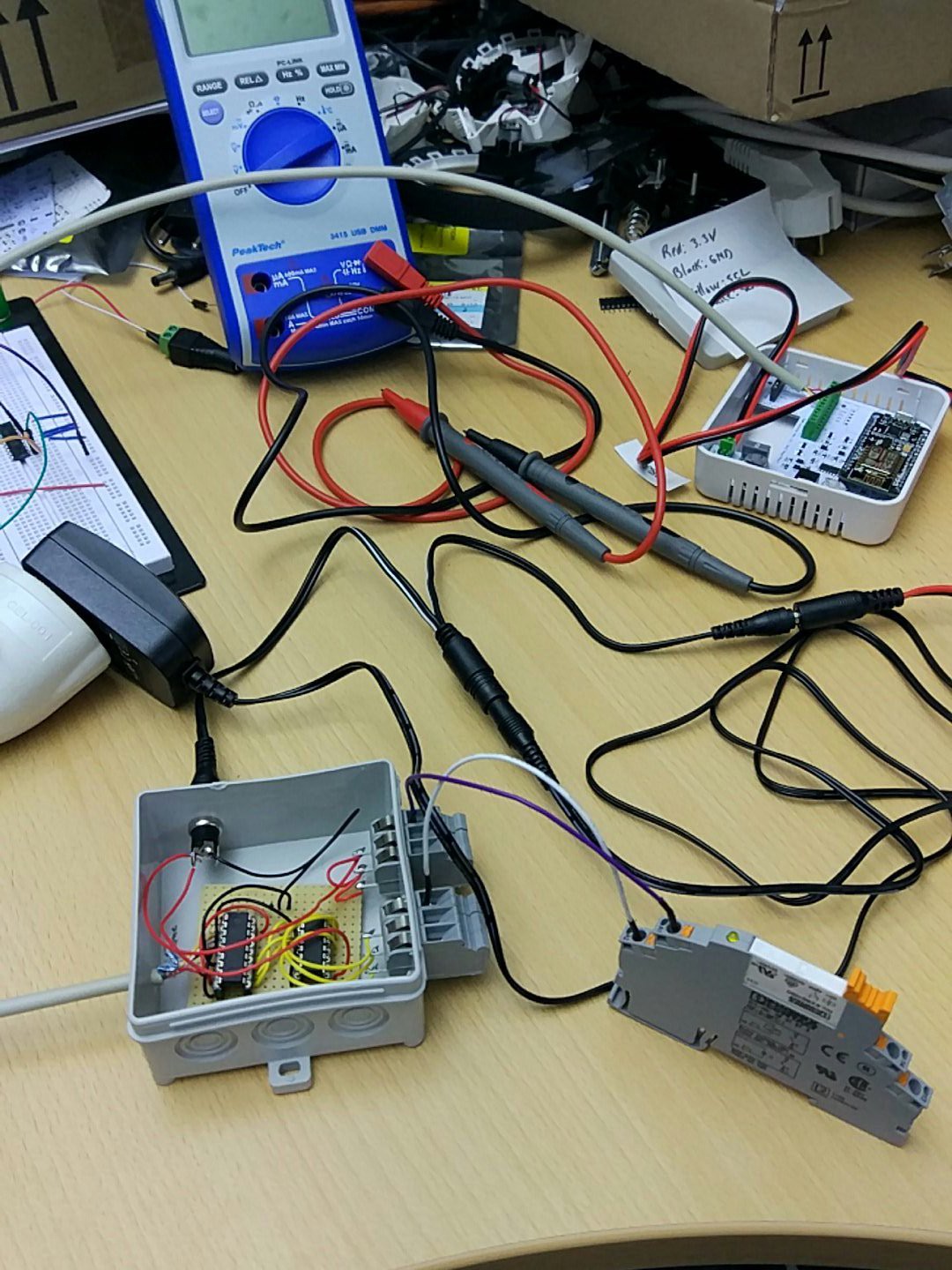
    An MCP23008 i2c-based GPIO expander along with an ULN2003 are used to control up to 3 relays (limited by the number of physical connectors, the ULN2003 can do up to 7 outputs). These relays (one pictured here as well) then control the 24 VAC to each thermoelectric actuator.

    With this little device hooked up to the i2c bus on the existing PCB (as pictured) three FCUs can have both their fans and valves controlled directly by the backend service.

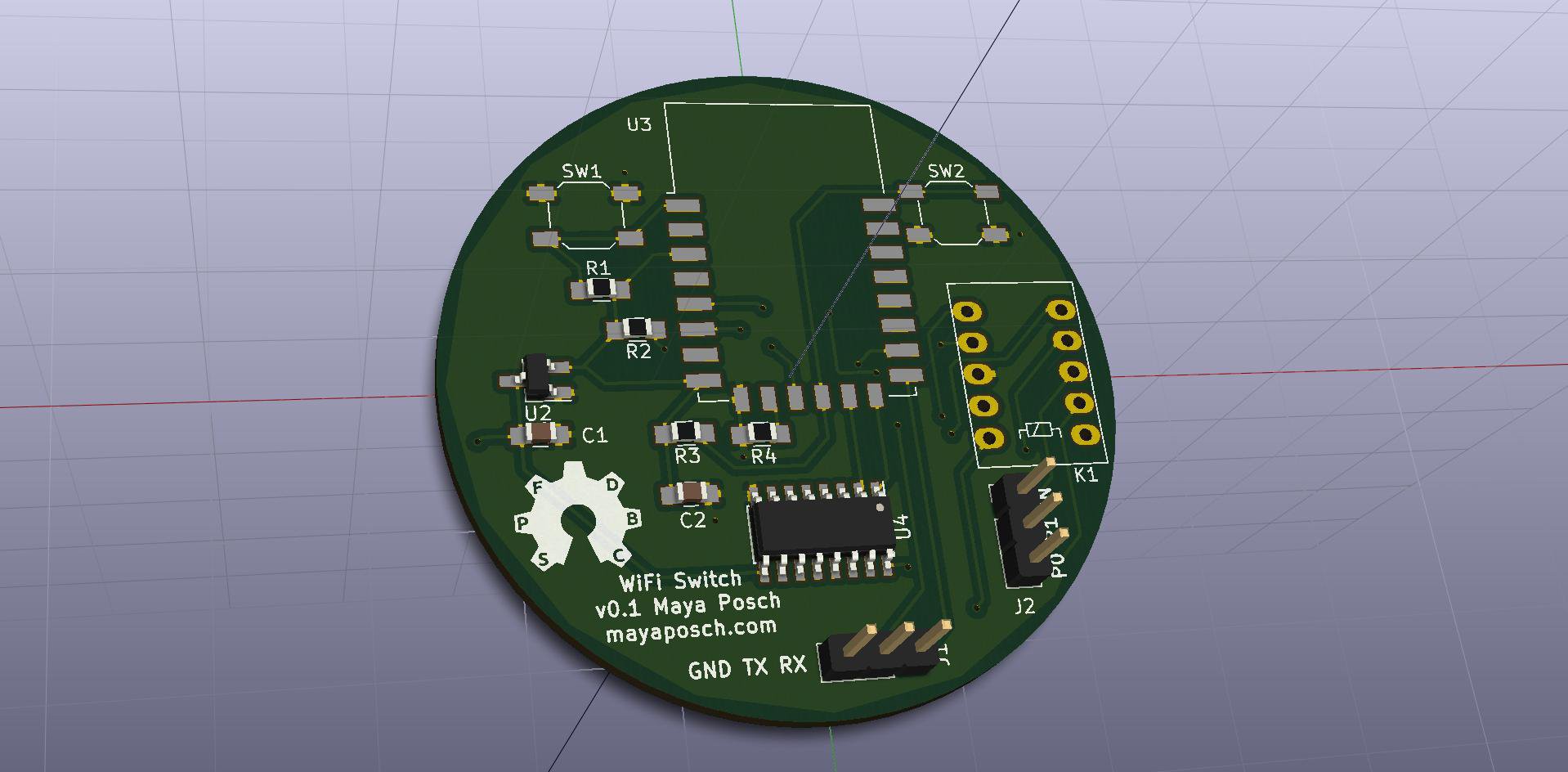
    In order to read out and control the water temperature in the entire section, the existing manual switch will be replaced with this little device:

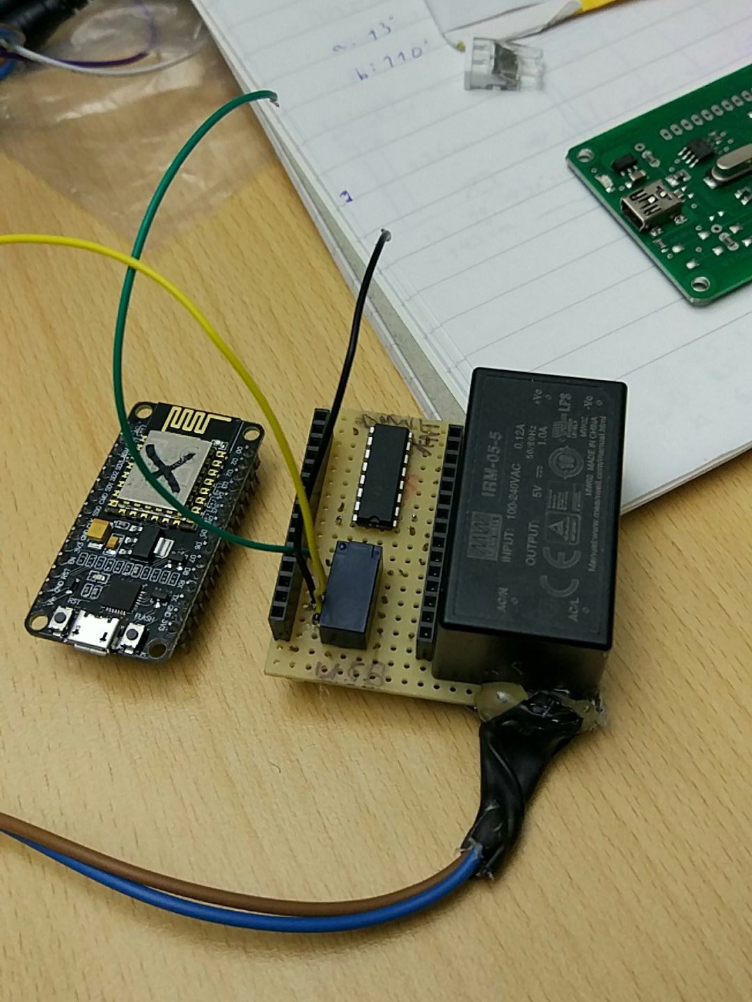
    This particular device was a bit of a doozy. Since the electrical box which it will be installed in does not have any wiring going into it other than the four signal wires (center, cooling/auto/heating), it was necessary to add a mains voltage SMPS module, for which a 230 VAC connection will be installed into the electrical box. Bit messy, but there you go.

    For this circuit another ULN2003 along with a latching relay (2-coil) was used. The NodeMCU (dead one used for test-fitting pictured) ESP8266 device controls two inputs (1B, 2B) on the ULN2003, which switches the relay between its two positions on both sides.

    One side of the relay performs the switching between heating/cooling, with the other side being used by the ESP8266 to read out the current state of the system (active low, with pull-ups enabled on the input pins).

    The relay controller has been tested already and will be installed next week. The 'IoT switch', as I have come to call it, will be tested and hopefully installed next week as well. Theoretically that means that along with the updates to the control service the prototype system as a whole will be done: controlling every aspect of these three FCUs in one room.

    As I will be leaving the company at the end of this month, I will only have time to complete things that far. The goal is however to also open source the (unified) firmware and related services, along with full documentation. I will endeavor to get all of this together as a complete package.

    This includes the PCB design, software and documentation. Here the v1.1 board design is almost done, but untested. There is also the idea to make a more integrated version, with the relay controller on the PCB instead of having it as a separate device.

    I would very much like to spend as much time on this project as I have over the past months, but until my life has stabilised itself somewhat, it is unlikely that I will have the opportunity to do so, barring me landing a paid job courtesy of this project...

    Read more »

  • First node successfully installed

    Maya Posch10/12/2017 at 18:31 0 comments

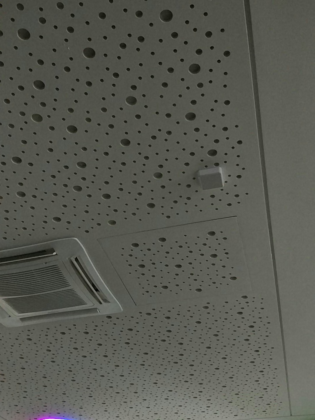
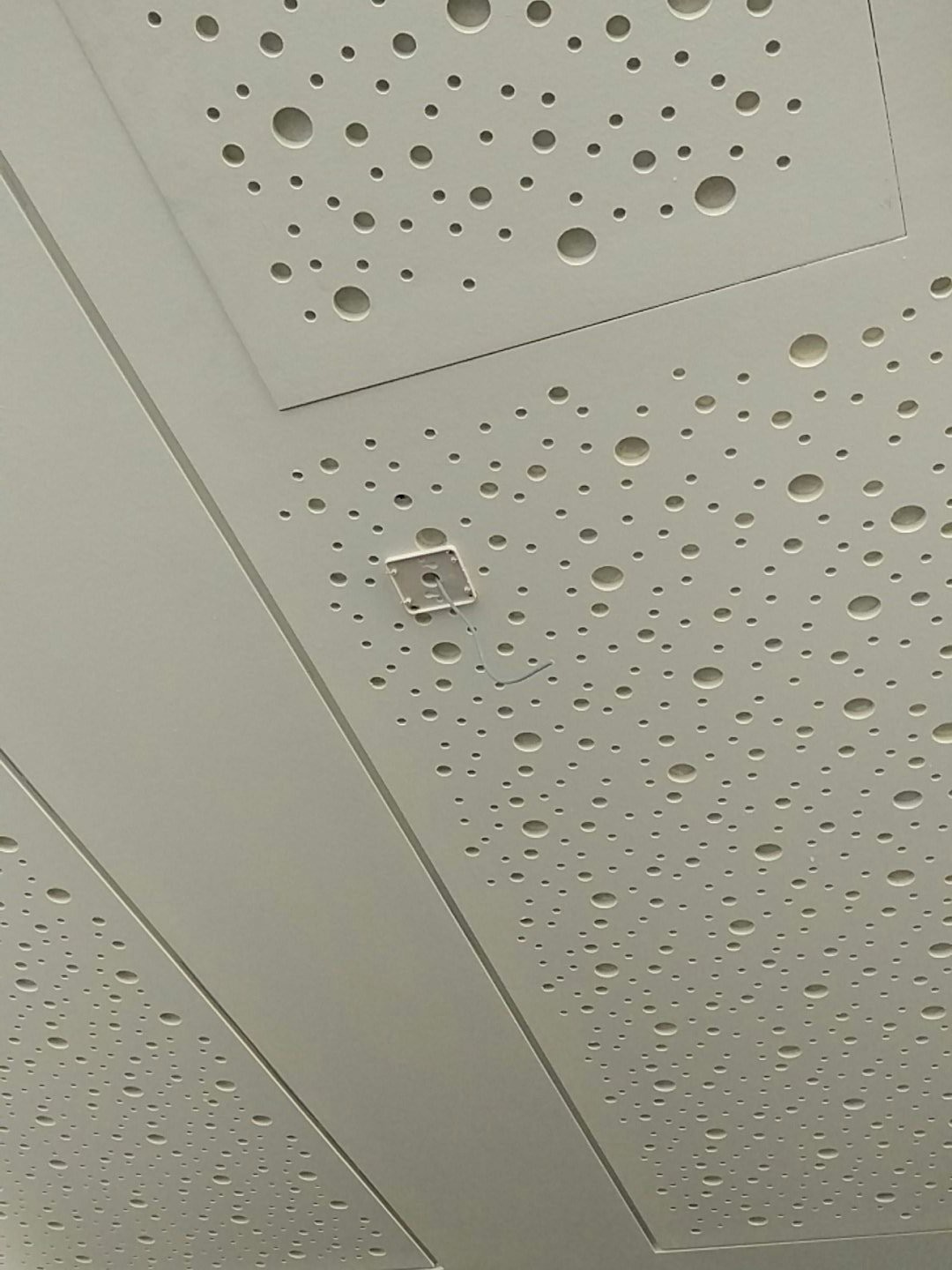
    Earlier today we had this:

    Which now looks like this:

    That's the first WiFi AC controller node (of 5 total) installed in an open plan office room. Initial tests show that the installed sensors (CO2, temperature, etc.) are functioning as expected, with the three connected AC units being supplied with an analogue signal.

    Outstanding issues at this point with the controller itself are some remaining (software) issues with the PWM routine (causing too much noise and a 1.5VDC lowest output on the controller), and a regression with the TLS handshake, causing an out of memory situation.

    As a result of this the connected AC units are supplied with at least 1.5VDC at the moment, causing their fan to keep spinning, albeit at a slow speed. It's expected that fixes to the firmware to get the PWM frequency at the target 1 KHz will fix this. Ideally an OTA update to the installed unit will suffice to fix this.

    Similarly for the TLS issue. This issue has been reported to the Sming project and I'm looking into it myself as well. Maybe it's going to be as simple to solve as the i2c bus issue which I was dealing with a few days ago, which turned out to be just swapped pin parameters in the i2c initialisation function.

    Another big remaining TODO is the lack of any kind of backend to control and drive the WiFi AC nodes with. This will be rectified over the coming days, so that one no longer has to manually send binary messages via MQTT to the target node :)

    Once this has been completed, and things are more or less working, I'll start working on open sourcing the board design (the v1.1 redesign) and the accompanying software. Stay tuned.


  • First big integration test coming up

    Maya Posch10/03/2017 at 10:30 0 comments

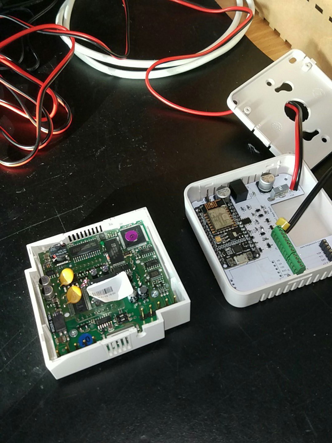
    After a few months of work, planning, learning to love KiCad and the intensely joyful experience of logistics concerning infrastructure in an office building, the first controller nodes will be installed soon. So far one signal wire has been connected to an AC unit (Sabiana SkyStar-ECM), with the following exciting result:

    Thrilling, right? :)

    Also interesting is a comparison with the old (wall-mounted) units that these new units are replacing:

    Old unit is on the left. Obviously.

    In this image the WiFi AC controller unit is controlling the AC unit in the same room, using the wiring the old unit normally connects to. Of note is that the old unit has two outputs (switchable between PWM/analogue) for driving a maximum of two AC units (or multiple chained, as happens in the main room of the office). The new unit can drive four AC units directly.

    During this and next week the last wiring will be installed and the six boards that were assembled so far tested and validated before being put up into their position on the ceiling. Fingers crossed :)

View all 7 project logs

Enjoy this project?

Share

Discussions

Lars Englund wrote 11/21/2017 at 22:02 point

Hi, I've been looking for a technical drawing of the camdenboss enclosure you are using to see where the screw holes and the PCB snap-in tabs are. I haven't found anything, could you share the documentation you used to make the PCB match the enclosure? Thanks!

  Are you sure? yes | no

Maya Posch wrote 12/01/2017 at 19:54 point

Hello Lars. I figured out the proper distances using vernier calipers on the enclosure. I will try to find my notes with those measurements, or measure on the PCB itself, and get back to you on this :)

  Are you sure? yes | no

Lars Englund wrote 12/01/2017 at 20:27 point

Thanks for the reply! I'm sorry I forgot to post back here when I actually found a technical drawing of camdenboss cbrs01vwh, it's available here:  http://docdro.id/V6BzhKO 

So no need to dig up the old notes, thanks alot for offering to!

  Are you sure? yes | no

Maya Posch wrote 12/01/2017 at 20:31 point

(Replying to my own post because no 'reply' option to follow-up comment)

Thanks for posting that PDF, Lars! :) I didn't even find it on the official CamdenBoss website (just the 'abbreviated' version). Wonder why the complete drawing went AWOL...

  Are you sure? yes | no

Similar Projects

Does this project spark your interest?

Become a member to follow this project and never miss any updates