Earlier today I realised that my CPLD boards have enough pins to be able to connect to the PCW. I hadn't really thought about it before, but in the back of my mind I knew that the PCW had a 50 way connector, but my CPLD only has 40 pins on each side. Then I realised that there are a bunch of power pins at the top and bottom of the edge connector, and when I checked, it turns out there are exactly 40 data pins. (Actually, 39, as one isn't connected). As I have a ribbon cable which goes from a 50 way edge connector to a 50 pin socket, I should be able to just connect the CPLD board to the right part of the connector and Bob's your uncle.
The only problem is that the PCW's clock signals don't come out where the GCK pins are on the CPLD, but hopefully 4MHz is slow enough that it doesn't matter. (Even 32MHz might be manageable).
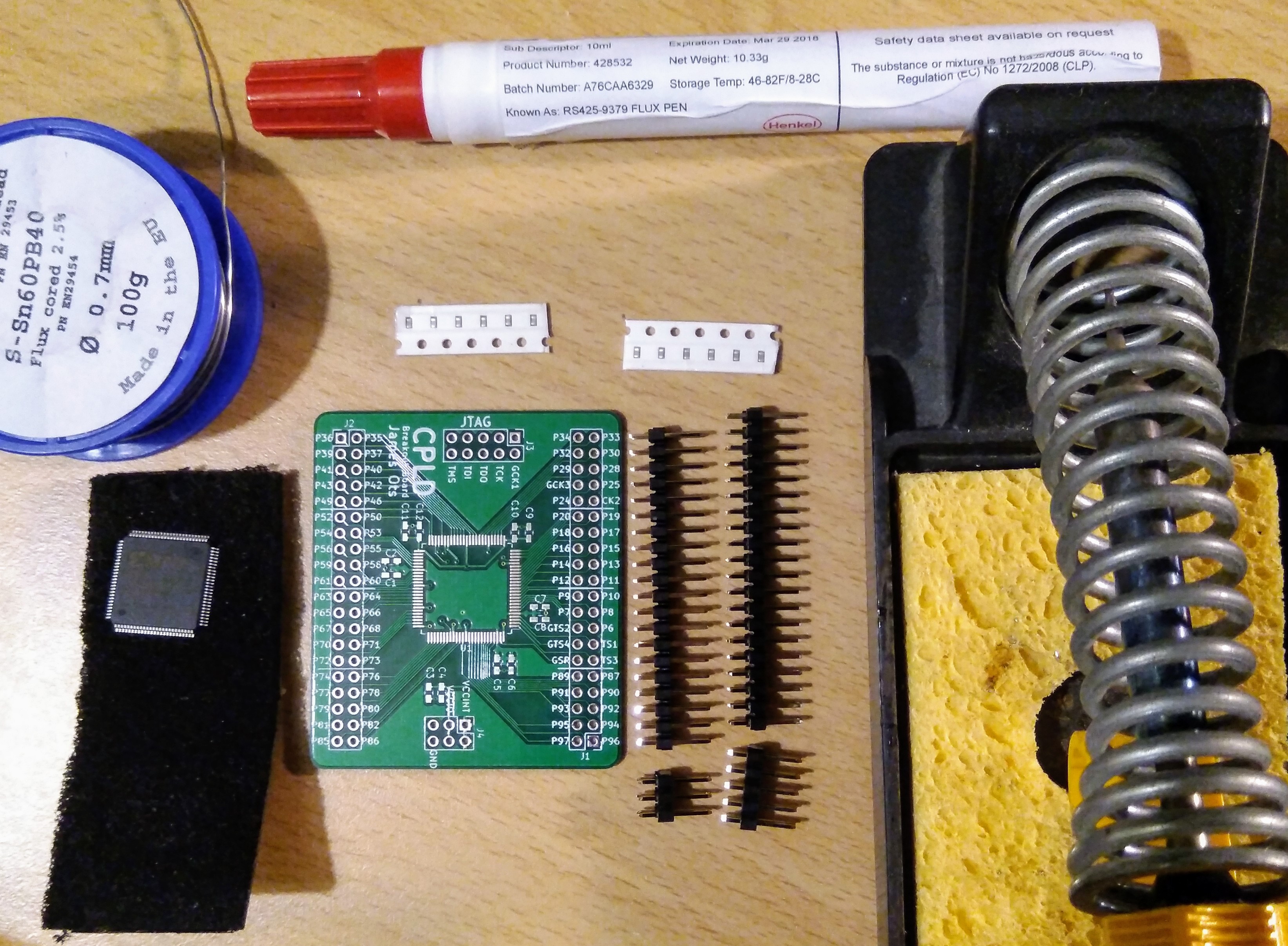
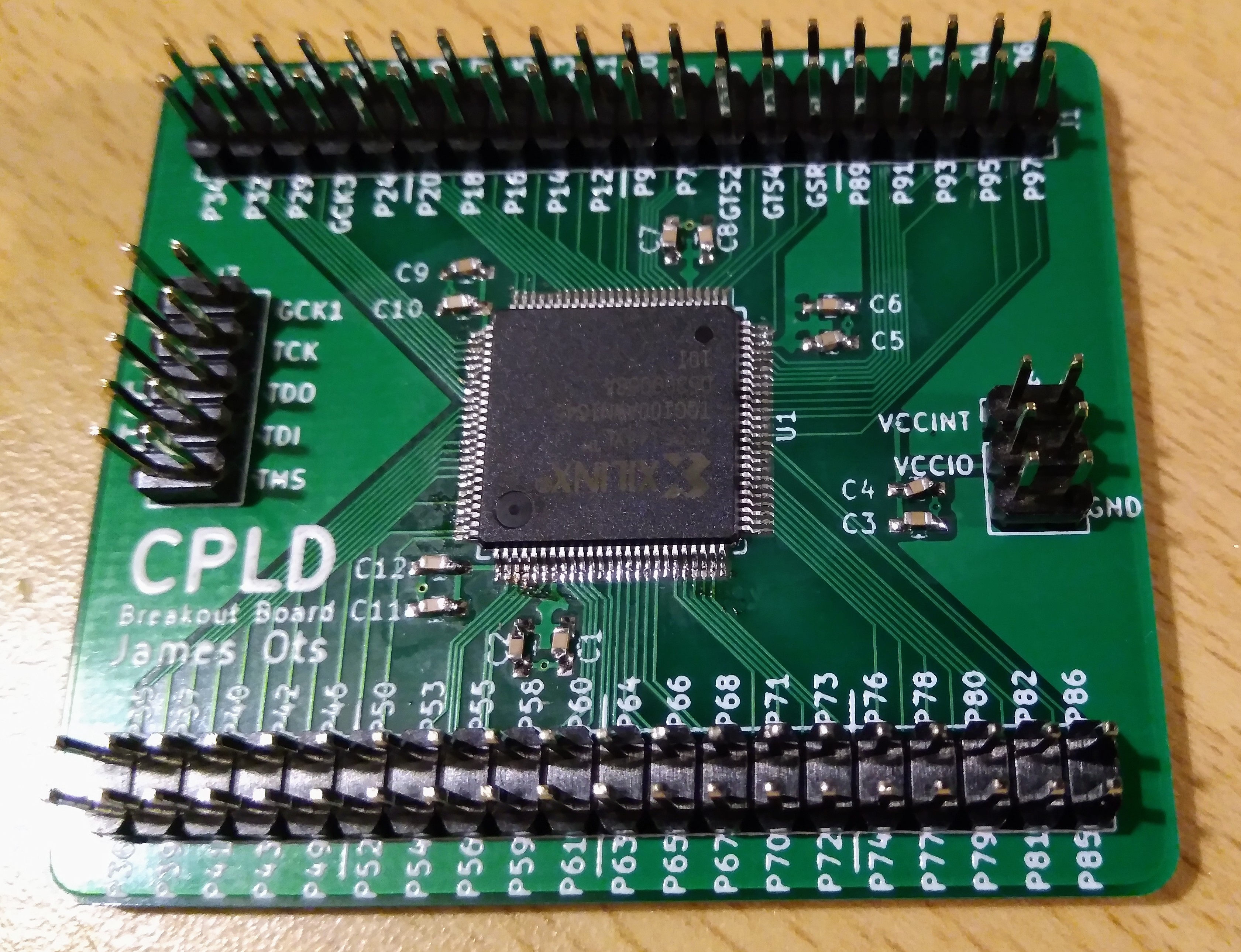
But what is my CPLD board? It's a breakout board I designed earlier in the year for my homebuilt Z80 project, which has a Xilinx XC95144XL on it, two banks of 40 pins headers and a JTAG interface. I use a separate FT232 interface to programme them.
I've made two so far. One is on my Z80 project, and the other got blown up when I got some voltages wrong! I had another CPLD chip waiting though, and the PCBs were made at Seeed Studio, where you get 10 boards at a time, so this evening I put it together.

I'm very short-sighted and usually wear contacts. This is usually just a minor annoyance, but when it comes to soldering surface mount components, it turns into a superpower. If I take my contacts out I can only focus on things which are about 10cm away, or nearer. Which is perfect for fiddly jobs like this. Of course, I wear safety goggles while soldering — you don't want hot flux spitting into your eyes.

Even with super eyesight, it's still pretty fiddly. The first side of the CPLD (the top in this picture) actually ended up being neatest — one stroke of the soldering iron and it was perfectly soldered. The other sides were a bit messy and needed some desolder braid to clean them up. But I think the SMD capacitors are harder to handle — it's just so easy to breathe too hard and send them flying off the desk, or they get stuck to the tweezers with flux, or soldered onto the tweezers by mistake.
I've done a quick continuity test and it looks like it's soldered correctly. Hopefully I haven't overheated the chip or anything, but we won't know until I test it out in a circuit, and that's not going to be tonight.
 James Ots
Discussions
Become a Hackaday.io Member
Create an account to leave a comment. Already have an account? Log In.