 James Ots
I was reading John Elliott's keyboard protocol information, and noticed that he says that he didn't know the exact timing for the keyboard. So I thought I'd find out, and connected a PCW keyboard up to my logic analyzer.
I was interested to find that although the overall idea is as he describes, the fine details of the wire protocol are actually a little different:
- John Elliott said that by default the data and clock lines float high, whereas although they are pulled high on the PCW motherboard, they are actually driven low most of the time.
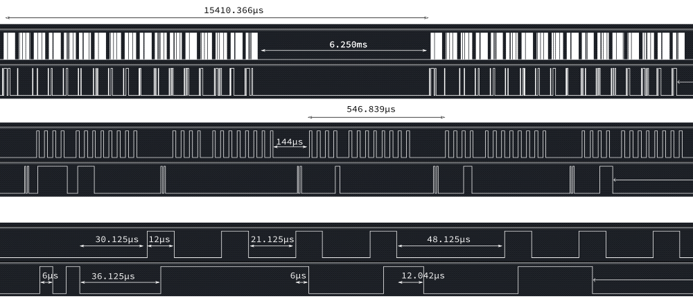
- The clock signal is quite a bit faster — there's only a 21µs gap between most clock pulses, although there is a 48µs gap after the fourth clock pulse.
- The data signal is valid on the back-end of the clock signal, not at the start. (Although since his clock signal is inverted, it is actually correct that it is valid on the falling edge of the clock!)
I tried three different PCW keyboards (all from 8256s), and they all had the same timings. The values transmitted did match John Elliott's description.
I imagine the actual timing of this is fairly irrelevant though — so long as the clock signal is within certain tolerances I would guess that the gate array just clocks the signal in on the falling edge of the clock.
So here's the output from the logic analyser, with some times added. The times seemed to be fairly consistent, but I should probably have used fewer decimal places. The overall time of a transmission of the keyboard state (top chart) should be pretty accurate though, as I took the time for 50 transmissions and divided it down, and the time for one row of transmissions (second chart) was also averaged from 8 transmissions.
Discussions
Become a Hackaday.io Member
Create an account to leave a comment. Already have an account? Log In.